FRONT SUSPENSION
GENERAL DESCRIPTION (Fig. 4-1)
The new Pivot Poise Suspension utilizes ball joints instead of knuckle supports, king pins and thrust bearings. The ball joints are riveted to the upper and lower control arms and are attached to the steering knuckle. The inner ends of the control arms are supported by bushings which are threaded onto pivot shafts and the pivot shafts are bolted to the frame. Caster and camber are controlled by shims placed between the upper pivot shafts and the frame.
The upper end of the coil spring seats on an insulator in the frame, and the lower end rests on a seat in the lower control arm.
The direct acting type, double action shock absorbers are mounted inside the coil springs. The upper end of the shock absorber is attached to the frame, and the lower end is attached to the spring seat in the lower control arm.
Rubber bumpers mounted on the upper control arms cushion their extreme downward movement and rubber bumpers on the lower control arms cushion their extreme upward movement.
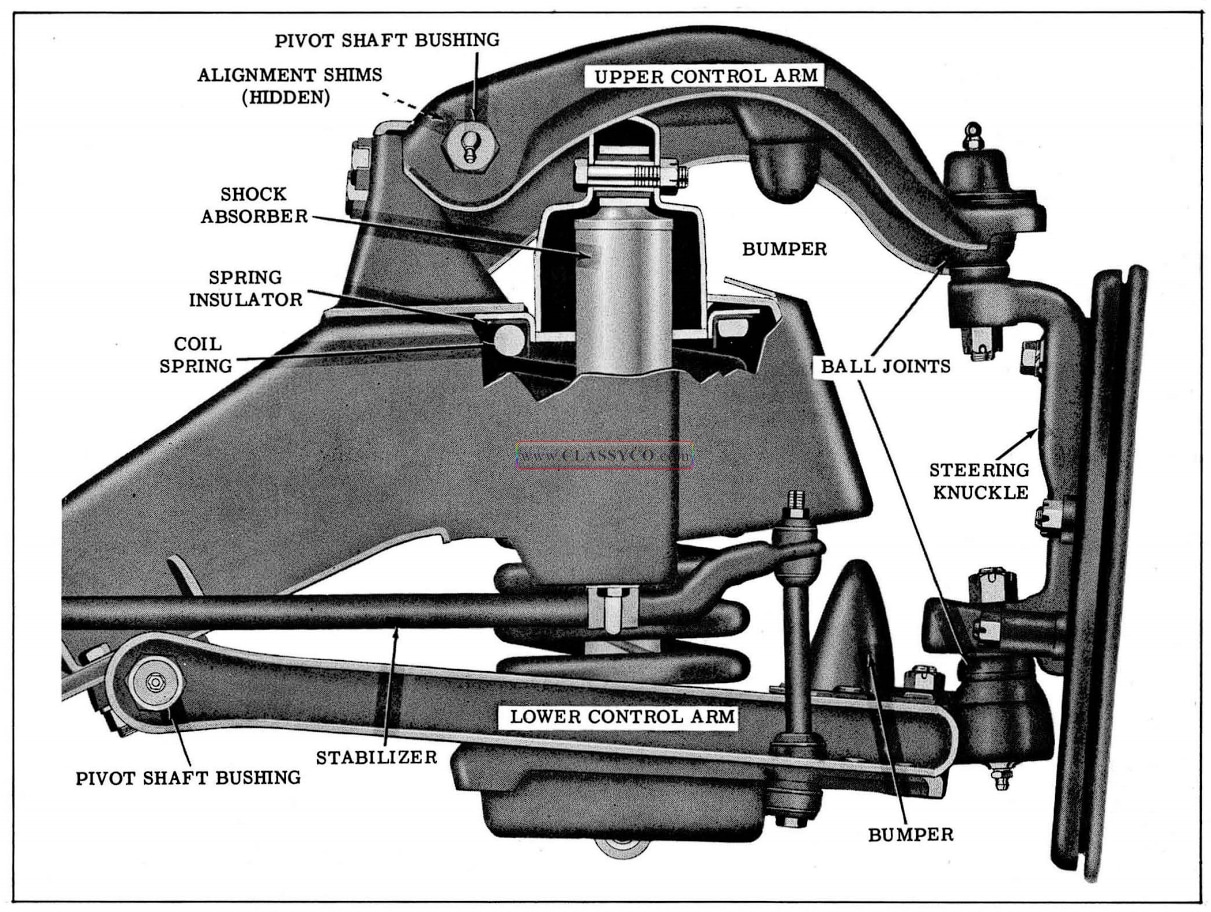
1957 Oldsmobile Front Suspension
WHEEL BEARING ADJUSTMENT (Fig. 4-2)
The proper functioning of the front wheel sus pension cannot be maintained unless the front wheel bearings are correctly adjusted. Cones must be a slip fit on spindle and bores lubricated to insure creep. Spindle nut must be a free running fit on threads.
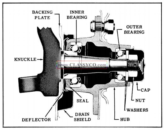
1957 Oldsmobile Steering Knuckle and Hub Assembly
The adjustment of front wheel bearings should be made as follows:
- Tighten adjusting nut with torque wrench to approximately 17 ft. lbs. to insure that all parts are properly seated and threads are free.
- Back off nut and retighten to 4 ft. lbs.
- If cotter pin hole in spindle and slot in nut line up, insert cotter pin; otherwise, back off adjusting nut to nearest line-up of slot and hole and insert cotter pin.
When installing front wheel hub and drum assembly, the complete inner bearing, including the cone, should always be assembled to the hub, and the assembly then installed on spindle. DO NOT PLACE THE INNER BEARING CONE ON WHEEL SPINDLE BEFORE INSTALLING WHEEL HUB AND DRUM.
SHOCK ABSORBERS
Shock absorbers are sealed at the factory and cannot be disassembled for servicing. In case of malfunction, they should be replaced.
CHECKING
Front shock absorbers can be checked on the car as follows:
- Disconnect both shock absorbers from lower control arms.
- By operating a shock absorber with each hand, work the units up and down. The movement of the shock absorbers should be smooth, and it should require equal force to operate both units.
NOTE: If the operation of the shock absorbers is erratic or unequal, one or both of the units are defective and will require replacement. In order to obtain proper riding characteristics, the shock absorbers must operate smoothly and at equal loads.
REMOVAL AND REPLACEMENT (Fig. 4-3)
- Remove pivot bolt from the upper end of shock absorber.
- Remove two cap screws and lock washers attaching shock absorber to lower control arm and remove shock absorber out through lower control arm spring seat.
NOTE: The upper and lower bushings are integral with the shock absorber and no service is required other than shock absorber replacement.
To install shock absorber, reverse sequence of operations. Torque the pivot bolt 60 to 70 ft. lbs. and the cap screws 15 to 25 ft. lbs.
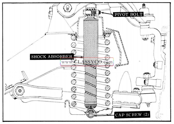
1957 Oldsmobile Shock Absorber Mounting
STABILIZER
REMOVAL AND REPLACEMENT (Fig. 4-4)
- Disconnect each side of stabilizer linkage by removing nut from top of link bolt; pull out bolt from bottom of linkage, and remove retainers, grommets, and spacer.
- Remove stabilizer bracket to frame bolts and remove stabilizer bar, rubber bushings, and brackets.
- To replace, reverse sequence of operations.
The rubber bushings should be positioned squarely in the brackets. Torque stabilizer link nut 8 to 18 ft. lbs. and bracket bolts 25 to 35 ft. lbs.
IMPORTANT: Never lubricate stabilizer bar rubber bushings · as they are dependent upon a bonding of the rubber to the bar for proper stabilizing action.
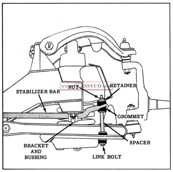
1957 Oldsmobile Stabilizer Bar and Linkage
UPPER CONTROL ARM ASSEMBLY REMOVAL
- Raise front of car and support lower control arms with floor stands.
NOTE: Since the weight of the car is used to relieve spring tension on the upper control arm, the floor stands must be positioned between the spring seats and ball joints of the lower control arms for maximum leverage.
- Remove the front wheel.
- Loosen the upper control arm ball joint from the steering knuckle as outlined below:
- Remove the cotter pin from the ball joint stud and clean threads of stud.
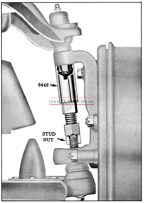
- Loosen the ball joint nut, then install Removing Tool 6446 as shown in Fig. 4-5.
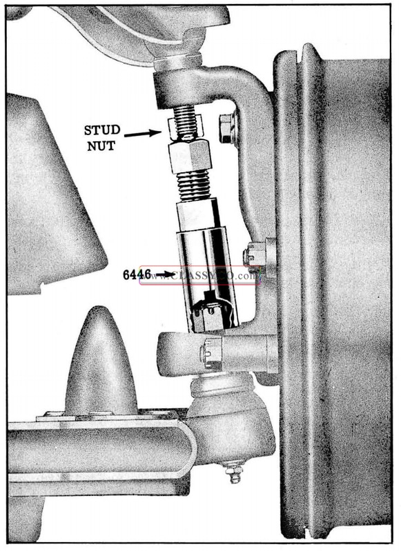
1957 Oldsmobile Loosening Upper Ball Joint
- Apply pressure on stud by expanding the tool until the stud breaks loose from the steering knuckle.
- Remove Tool 6446 and ball joint nut, then pull stud free from knuckle.
- Support the hub and drum assembly to prevent the weight of the assembly from damaging the brake hose.
- If necessary to remove pivot shaft from control arm, loosen pivot shaft bushings at this time.
- Remove the pivot shaft to frame attaching bolts, nuts, lock plate, and wheel alignment shims, then remove control arm and pivot shaft from car. (See Fig. 4-6)
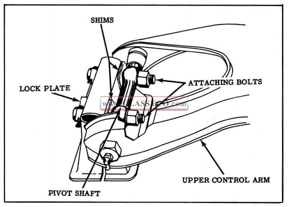
1957 Oldsmobile Upper Control Arm Mounting
NOTE: Keep alignment shims grouped so that they may be reinstalled in their original location during reassembly.
UPPER CONTROL ARM DISASSEMBLY AND ASSEMBLY
NOTE: The ball joint is riveted to the control arm and should not be removed. If necessary to replace either the control arm or the ball joint, they should be replaced as an assembly.
- Remove pivot shaft bushings and shaft from control arm.
- Apply chassis lubricant to pivot shaft threads and install rubber seals on shaft.
- Position pivot shaft in control arm and while holding shaft centered, start bushings on shaft and into arms.
- Tighten bushings until they are solidly seated.
- Rotate pivot shaft so that pivot shaft bolt holes are centralized in control arm. (See Fig. 4-7)
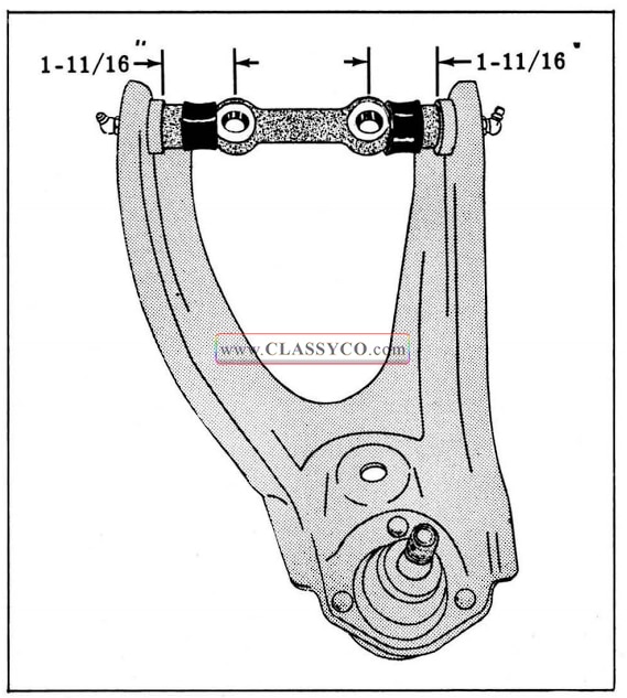
1957 Oldsmobile Upper Pivot Shaft Installation
UPPER CONTROL ARM-INSTALL
- Position pivot shaft on the frame, then install pivot shaft attaching bolts, nuts, and lock plate with the original alignment shims installed between the pivot shaft and frame on their respective bolts. Torque nuts 100 to 110 ft. lbs.
- Remove the temporary support from the hub and drum assembly, then connect the ball joint to the steering knuckle. Torque nut 40 ft. lbs. (minimum) and install cotter pin. Tighten nut further, if necessary, to install cotter pin.
- Install wheel and lower car.
- Check wheel alignment and adjust if necessary.
LOWER CONTROL ARM ASSEMBLY AND/OR COIL SPRING
REMOVE
IMPORTANT: If a worn ball joint is suspected, check by attempting to chuck the top of the wheel in and out with the weight of the car on the wheel. Under any other condition the lower ball joint will appear to be worn regardless of its actual condition.
- Raise front of car and support with floor stands.
- Remove wheel assembly.
- Disconnect stabilizer link from lower control arm.
- Remove shock absorber.
- Install Tool 6509 in shock absorber mounting in spring seat as shown in Fig. 4-8.
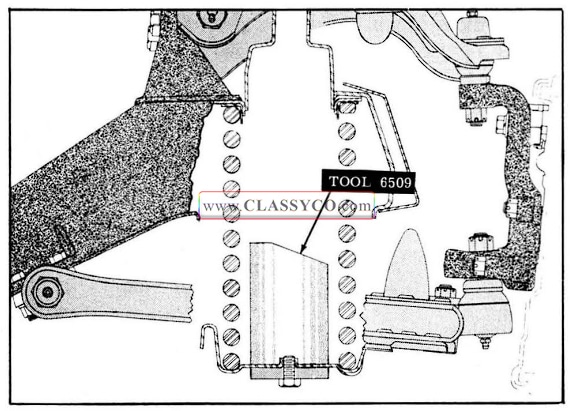
1957 Oldsmobile Spring Pilot Tool Installation
- Raise floor jack until it supports lower control arm between spring seat and ball joint.
- Disconnect the lower control arm ball joint from the steering knuckle as outlined below:
- Remove the cotter pin from the ball joint stud and clean threads of stud.
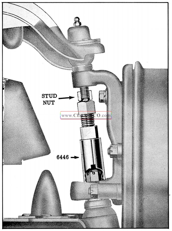
- Loosen the ball joint nut, then install Ball Joint Removing Tool 6446 as shown in Fig. 4-9.
1957 Oldsmobile Loosening Lower Ball Joint
- Apply pressure on stud by expanding the tool until the stud breaks loose from the steering knuckle.
- Remove Tool 6446 and ball joint nut.
- Slowly lower floor jack until spring is fully extended and remove spring.
IMPORTANT: The left and right coil springs are not interchangeable. The coil spring part number is stamped on the outer side of the end coil.
- If necessary to remove lower control arm, remove pivot shaft to cross member attaching bolts.
LOWER CONTROL ARM
Disassembly and Assembly
NOTE: The ball joint is riveted to the control arm and should not be removed. If necessary to replace either the control arm or the ball joint, they should be replaced as an assembly.
- Remove pivot shaft bushings and shaft from control arm assembly.
When installing a NEW lower control arm, the bushings must cut their own thread in the new control arm; therefore, an expander tool must be used to prevent the arms from moving inward during bushing installation. If old lower control arm is to be used the expander tool is not necessary. However, be sure pivot shaft bushings properly engage existing threads in control arm so there is no bind.
If a new control arm is to be installed:
- Place Tool J -1052 in position and expand until distance between inside surfaces of inner ends of control arm assembly is 11-1/2″. (See Fig. 4-10)
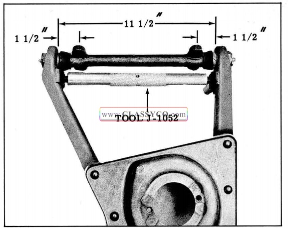
1957 Oldsmobile Lower Pivot Shaft Installation
- Apply chassis lubricant to pivot shaft threads and install rubber seals on shaft.
- Position pivot shaft in control arm, and while holding shaft centered, start bushings on shaft and into arms.
NOTE: Threads can be cut in a new control arm more easily if a coating of white lead is applied to the O.D. of the bushing.
- Tighten bushings until they are solidly seated against the shoulder.
- Remove expander tool and rotate shaft so that pivot shaft bolt holes are centralized in control arm. (See Fig. 4-10)
LOWER CONTROL ARM AND/OR SPRING
Install
- If the lower control arm was removed, connect control arm pivot shaft to frame cross member. Torque pivot shaft bolts 65 to 75 ft. lbs.
- Tape spring rubber insulator to the top of spring.
IMPORTANT: The left and right coil springs are not interchangeable. The top of the spring may be identified by a flat coil which will allow the insulator to seat squarely on the top coil.
- While holding spring and insulator against pilot in frame cross member, tilt spring so it will pilot over Tool 6509 in lower control arm. (See Fig. 4-11) Rotate spring so the end of the bottom coil will index with edge of hole in control arm spring seat. The coil should not cover any portion of the hole.
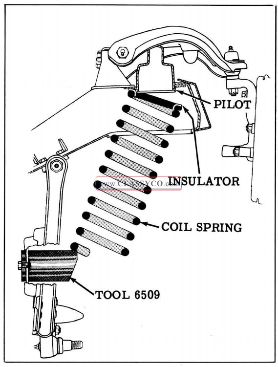
1957 Oldsmobile Coil Spring Positioning
- Position floor jack between spring seat and ball joint. Chain the upper control arm to the base of the jack.
- Raise control arm until the ball joint is tight in steering knuckle. Install ball joint nut and tighten to 40 ft. lbs. (minimum) and install cotter pin. Tighten nut further, if necessary, to install cotter pin. (See “Note” next page)
NOTE: A screwdriver slot is provided in the ball joint stud as a means of preventing the stud from turning when tightening the ball joint nut.
- Remove Tool 6509 and install shock absorber.
- Connect stabilizer link to lower control arm.
- Install wheel and lower car.
- Check caster, camber, and toe-in, and adjust if necessary.
STEERING KNUCKLE
REMOVE
- Raise front of car and support lower control arms with floor stands.
NOTE: Since the weight of the car is used to relieve spring tension on the knuckle, the floor stands must be positioned between the spring seats and ball joints of the lower control arms for maximum leverage.
- Remove front wheel and hub and drum assembly.
- Remove backing plate without disconnecting brake hose. Leave plain arm connected to tie rod end.
NOTE: Support the backing plate assembly out of way to avoid any strain on brake hose.
- Disconnect the control arm ball joints from the steering knuckle as outlined below:
- Remove cotter pin from upper ball joint.
- Loosen the upper ball joint nut, then in stall ball joint removing Tool 6446 as shown in Fig. 4-12.
1957 Oldsmobile Loosening Upper Ball Joint (2)
- Apply pressure on stud by expanding the tool until the stud breaks loose from the steering knuckle.
- Repeat steps a, b, and c on the lower ball joint stud.
- Remove Tool 6446 and ball joint nuts.
- Remove the steering knuckle from car.
INSTALL
- Connect the lower ball joint to the steering knuckle. Torque stud nut 40 ft. lbs. (minimum) and install cotter pin. Tighten further, if necessary, to install cotter pin.
NOTE: A screwdriver slot is provided in the lower ball joint stud as a means of pre venting the stud from turning when tightening ball joint nut.
- Repeat Step 1 on upper ball joint.
- Install backing plate and plain arm to steering knuckle. Torque nuts 55 to 60 ft. lbs.
- Install wheel and hub and drum assembly and adjust wheel bearings.
- Lower car.
- Check camber, caster, and toe-in and adjust if necessary.
TUBELESS TIRES
The tubeless tires used by Oldsmobile as original equipment have a safety inner liner which, if punctured, tends to cling to the penetrating object, forming a temporary seal until the object is re moved. After this type of tubeless tire has been punctured, it should be repaired as covered in this section.
CHECKING TIRES FOR LEAKS
- With wheel assembly removed, inflate tire to recommended pressure.
- Submerge wheel assembly in a water tank or run water over tire to locate leak. Mark location of lea k with crayon.
DEMOUNTING TUBELESS TIRES
- With wheel assembly removed, remove valve cap and core to deflate tire.
- Use commercial type bead breaker to loosen tire sealing beads from rim.
CAUTION: DO NOT use tire irons for breaking beads from rim as this may damage beads.
- Remove the outside bead from the rim by using two tire irons.
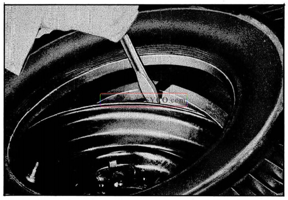
- Turn the tire over and again use tire irons, one between the rim and bead to pry the rim out, the other to pry outward between the tire bead and rim as shown in Fig. 4-13.

1957 Oldsmobile Removing Tire
REPAIRING TUBELESS TIRES
There are several methods of repairing tube less tires. Oldsmobile recommends only two methods for repairing punctures not exceeding 3/16″.
- The Hot Patch Method:
This method uses a patch which requires heat (either self-contained or electrically applied) to vulcanize the patch to the tire.
- The Self-Vulcanizing Method:
In this method, no heat is required because the vulcanizing action is chemically performed.
Hot Patch Repair Method
- Clean out the injury with hand rasp furnished with the tire repair kit.
- Using sealing gun, fill puncture from the outside of the tire as shown in Fig. 4-14.
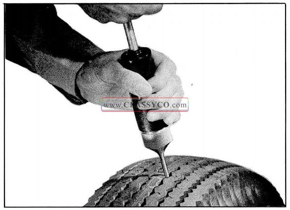
1957 Oldsmobile Using Sealer Gun
- Thoroughly clean inside of tire around injury with methyl chloroform. Allow the cleaned area to dry.
- Roughen area around injury with hand buffer or wire brush.
- Spread an even coating of rubber cement over the puncture, slightly larger than the patch area, and allow it to dry for 5 minutes.
- Remove protective tape from patch on patches containing own source of heat. Prepare patch material for igniting by loosening material with point of a knife blade.
- Carefully center patch over injury and hold in place using special clamp. Tighten clamp maximum finger tight. (See Fig. 4-15)
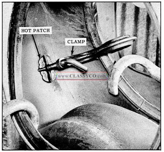
1957 Oldsmobile Hot Patch Application
- Apply heat to patch. Allow to cool 15 minutes.
- If self-contained heat patch was used, carefully remove metal cup and blow out any ashes remaining in tire.
Self-Vulcanizing Method
(Firestone Tubeless Tire Repair Kit #3-K-164)
NOTE: This method should be used only for tires WITHOUT soft puncture-sealing material on the inside surface of the tire. The following procedure should be followed in using the kit.
- Clean out the injury with the awl to remove puncturing object and foreign material.
- Thoroughly clean the inside of the tire around the injury with methyl chloroform. Allow to dry.
3.. Fill the injury with Filler Rubber (supplied in the kit) using the awl as follows:
- Clean awl needle and dip in Self-Vulcanizing Fluid. From inside of tire, force needle through tire until point extends beyond tread.
- Remove detachable handle from awl needle. Cut 1/8″ by 1″ strip of Filler Rubber, re move protective cover and insert into hole of awl needle with end of rubber strip ex tending beyond the needle. (See Fig. 4-16)
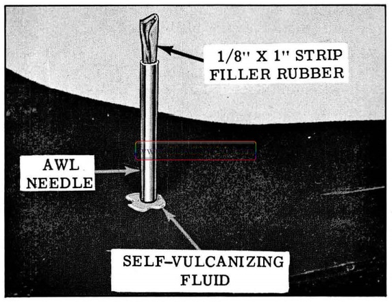
1957 Oldsmobile Sealing Injury with Filler Rubber
- Pull needle through tire with pliers. Frier Rubber will remain in the puncture. Cut off excess rubber flush with inside of tire.
The injury may also be filled from the outside or inside of the tire with a sealant gun. Hold gun tip firmly against puncture and force sealant until it comes through the other side of the tire.
- Thoroughly roughen area around puncture, slightly larger than patch, with wire brush included in kit. Remove all traces of lubricant, foreign material, etc. Do not use additional solvent after buffing.
- Apply an even coating of Self-Vulcanizing Fluid over buffed area. IMPORTANT: Allow to dry 5 minutes until no longer tacky.
- Remove foil backing from patch. Place over injury and iron down firmly, especially the edges, with roller tool included in kit. To prevent buckling and insure a good seal, roll patch from the center toward the outer edges. (See Fig. 4-17) Vulcanization is completed chemically. The repaired tire can be placed back in service immediately.
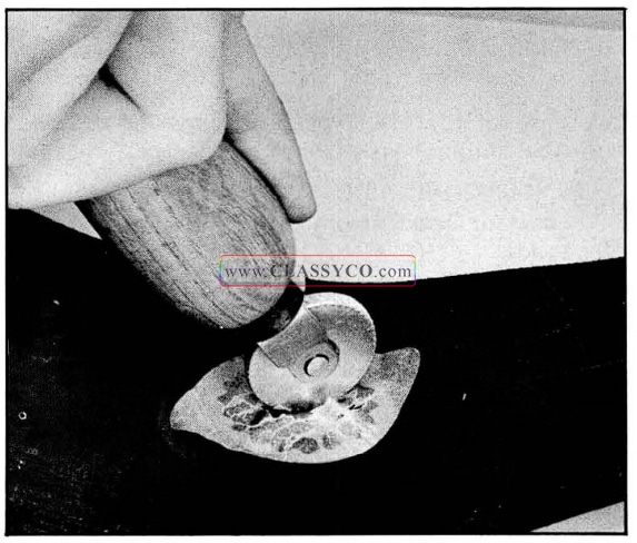
1957 Oldsmobile Rolling Patch
VALVE REMOVAL AND REPLACEMENT (Tire Removed)
To remove a rubber “snap-in” valve from rim, force a small screwdriver blade between valve and edge of hole. Then, while prying on valve to start groove out of edge of hole, push the valve back through the rim.
IMPORTANT: To insure against air leaking around the valve, always use a new valve once a valve is removed from the rim.
The one piece “snap-in” type rubber valve is installed as follows:
- Clean all particles of foreign matter from around the area and the edges of the valve hole in the rim with steel wool.
- Use water or a very light film of tire lubricating liquid soap GM-2251 or Ru-Glyde to lubricate the outside of the valve.
NOTE: DO NOT USE GREASE OR DRY SOAP.
- Insert the “snap-in” type rubber valve through hole in rim as far as it will go.
DO NOT attempt to drive the valve in place in the rim.
DO NOT grip the threads of valve with a pair of pliers and attempt to pull valve into rim.
- Use a tire valve fishing tool as shown in Fig. 4-18 and pull the valve through hole in rim until valve snaps into position.
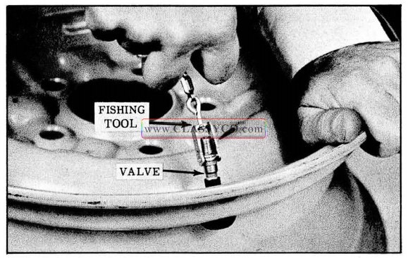
1957 Oldsmobile Installing Valve
MOUNTING TUBLESS TIRES
Extreme care must be exercised to prevent injury to the sealing bead and circumferential bead when forcing tire over rim.
Tire mounting machines or tire irons can be used.
- Apply a light film of tire lubricating soap GM-2251 or Ru-Glyde to sealing beads of tire.
NOTE: DO NOT use excessive lubricant as this may lead to rim slippage and sub sequent breakage of air seal.
- Carefully mount first bead in usual manner. If tire irons are used, take small “bites” around rim being careful not to injure the tire bead. (See Fig. 4-19)
1957 Oldsmobile Mounting Tire
CAUTION: DO NOT use a hammer, as damage to bead will result.
- Install outer bead in the same manner.
With references to Fig. 4-20, you will note a tire mounting band is slipped around the outside of the tire to compress center of tire tread to force bead out against the rim seats. A sash cord winched around a jack handle will serve the same purpose.
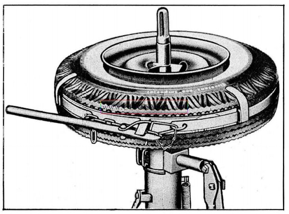
1957 Oldsmobile Tire Mounting Band
Tubeless tires are packaged with a cardboard liner which forms tires so the beads are forced out. This eliminates the use of special expanding equipment.
- While holding the tire in upright position, press against the outside of the wheel. This will start the outside bead onto the bead seat.
- Next, lean the tire so the weight of the wheel will help seat the inside bead.
- Give a few quick “shots” of air to seat the tire beads on the bead seats.
CAUTION: Keep hands away from tire bead rim during this operation.
- Inflate tire to 40 pounds.
- Check to be sure that the bead positioning rib (outer ring of tire) is visible evenly just above the rim flange all the way around tire, both sides.
- Deflate to recommended air pressure.
TIRE INFLATION
The importance of proper tire inflation cannot be over emphasized. Maintenance of the correct inflation pressure is one of the most important elements in tire care.
Recommended Tire Pressure (Tires Cold):
With Air Conditioning (8:50 x 14 Tires only) 24 lbs. (From) 20 lbs. (Rear)
All Others 22 lbs. (Front) – 20 lbs. (Rear)
Too great a tire pressure is detrimental, but not so much as under-inflation. Higher inflation pressure than recommended will cause:
- A harder riding car.
- A tire more susceptible to various types of bruises.
- Tire chatter, resulting in uneven wear.
- Excessive wear at the center of the tire tread.
Even when a tire is properly inflated, it is not round. It is flat where it contacts the road so that the car at all times is in effect being pushed up hill. This condition is exaggerated on an underinflated tire. Inflation pressures lower than recommended will result in:
- Higher gasoline consumption.
- Rapid and uneven wear on the edges of the tire tread.
- A tire more susceptible to rim bruises and various types of rupture.
- Increased cord fatigue or broken tire cords.
- Hard steering.
- High tire temperatures.
- Car roll on sharp curves.
- Tire squeal on curves.
TIRE NOISE
Complaints of axle noise are more frequently caused by tires than by differential gears, bearings, etc.
Tire noise is frequently diagnosed as axle noise. The process of determining whether the noise is caused by tires is relatively simple. Tire noise is related directly to the speed of the car and the road surface. Tests made for drive, float, and coast noise as used for differential testing will have little or no effect on noise level if tires are the cause.
VARIOUS TYPES OF TIRE WEAR
Tire wear may be divided into the following classifications:
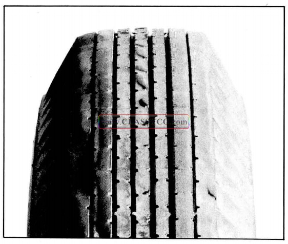
- Side wear due to improper camber. (See Fig. 4-21)
1957 Oldsmobile Side Wear Due to Camber
- Side wear due to rounding turns at high rate of speed (cornering). (See Fig. 4 22)
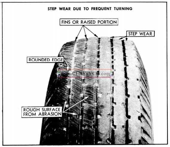
1957 Oldsmobile Cornering Wear
- Side wear due to excessively crowned roads.
- Toe-in or toe-out misalignment wear. (See Fig. 4-23)
1957 Oldsmobile Toe-In or Toe-Out Wear
- Uneven tire wear due to bent, loose, or misaligned parts (Mechanical Condition). (See Fig. 4-24)
1957 Oldsmobile Wear Due to Mechanical Condition
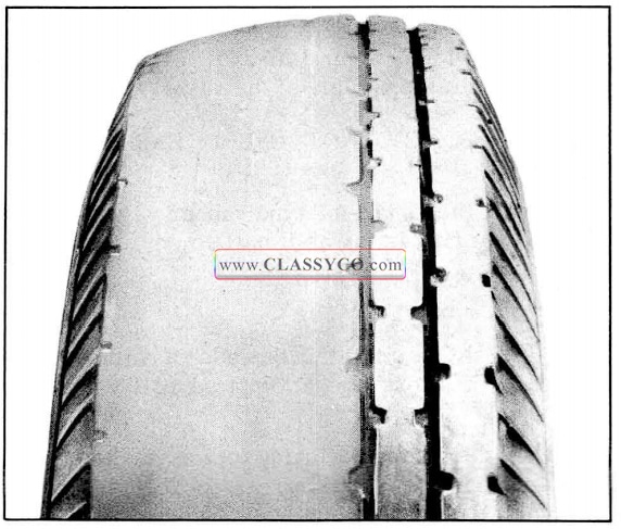
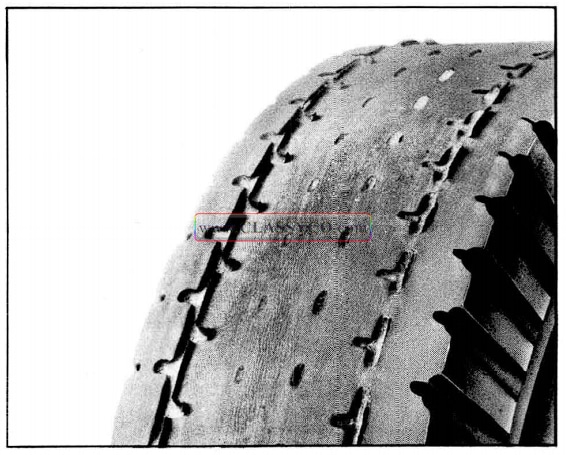
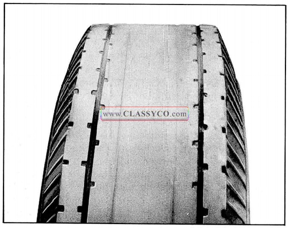
- Side wear due to under-inflation. (See Fig. 4-25)
1957 Oldsmobile Under Inflation
- Side wear due to unbalanced tire and wheel.
- Rapid and uneven wear caused by sudden starts and stops.
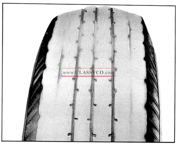
- Tread wear due to over-inflation. (See Fig. 4-26)
1957 Oldsmobile Over Inflation
Correction for Tire Wear
Correction for tire wear from excessive camber, caster, toe-out, and toe-in is a complete check and proper alignment of the front wheels.
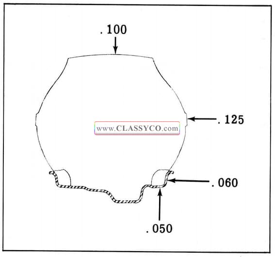
TIRE AND WHEEL RUNOUT
Wheel and tire assemblies may be checked for runout with a dial indicator at points shown in Fig. 4-27. Runout should not exceed the following limits:
Tire Runout: Radial .100″
Lateral .125″
Wheel Runout: Radial .050″
Lateral .060″
NOTE: Tire runout should be checked as soon as possible after car has been driven to avoid false readings due to the tendency of tires to take a temporary “set” after standing for a few hours.
1957 Oldsmobile Runout Specifications
WHEEL AND TIRE BALANCE
Wheel, tire, and brake drum balance must be maintained within certain limits; otherwise, wheel tramp and high speed shimmy will result.
Front wheel “tramp” and front wheel “shimmy” are two entirely different conditions. Front wheel “tramp”, which usually occurs at high speed, is a wheel “hop” caused from an unbalanced condition of wheels, loose linkage in the front end, or improperly operating shock absorbers.
“Shimmy” may occur at the lower speeds and is a wobbly condition of the front wheels caused from an unbalanced condition, loose front end linkage, loose steering gear parts, or faulty steering gear adjustment. “Tramp” and “shimmy” will be felt in the whole car however, “shimmy” can also be felt at the steering wheel. “Shimmy” is a front wheel condition entirely, whereas it is possible to have “tramp” in front or rear wheels.
Due to the irregularities in tread wear caused by sudden brake application, misalignment, low inflation pressure, or tire repair, ere·., a wheel and tire assembly may lose its original balance. Consequently, if front end instability develops, the tire and wheel assembly should be checked for static and dynamic balance.
WHEEL ALIGNMENT
Front wheel alignment is the mechanics of adjusting all the inter-related factors affecting the running and steering of the front wheels of the automobile. Incorrect alignment of front wheels will result in hard steering and abnormal tire wear.
The front wheel alignment factors are:
- CASTER (See Fig. 4-28)
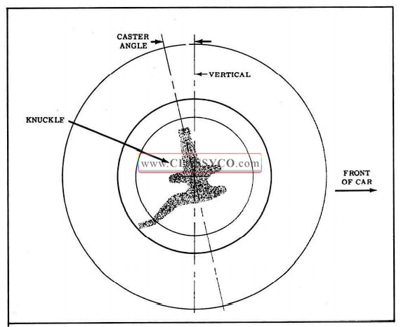
1957 Oldsmobile Front Wheel Caster
- CAMBER (See Fig. 4-29)
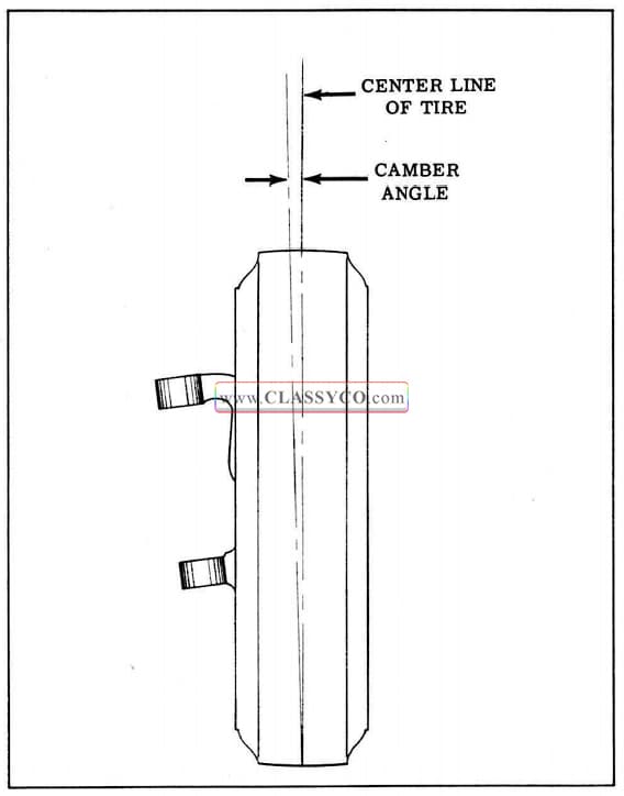
1957 Oldsmobile Front Wheel Camber
- TOE-IN (See Fig. 4-31)
- TOE-OUT (STEERING GEOMETRY) (See Fig. 4-33)
Before any attempt is made to check or correct Caster, Camber, Toe-In or Toe-Out, the following preliminary checks and necessary corrections should be made on those parts which influence the steering of the car:
- Inflate tires to recommended pressure.
- Check front wheel bearings for proper preload.
- Check front wheels and tire assemblies for radial and lateral runout.
- Grasp front bumper in center and raise and lower front end several times to allow frame to come to its normal level. Check for erratic shock absorber action.
The method of checking alignment will vary depending on the type of equipment being used. The instructions furnished by the manufacturer of the equipment should be followed.
NOTE: Caster angle and camber angle should be within 1/2° between right and left sides of car for best handling characteristics: Check front wheel alignment without passengers or load in or on car.
CASTER AND CAMBER ADJUSTMENT
(Caster 0° to ¾° +)
(Camber ¾° + to ¾° -)
IMPORTANT: A POSITIVE caster is required on 1957 models instead of NEGATIVE caster used on past models.
Camber and Caster are adjusted by shims placed between the upper pivot shafts and the frame. (See Fig. 4-30) Both caster and camber adjustments can be made at the same time after the wheel alignment checks have been completed.
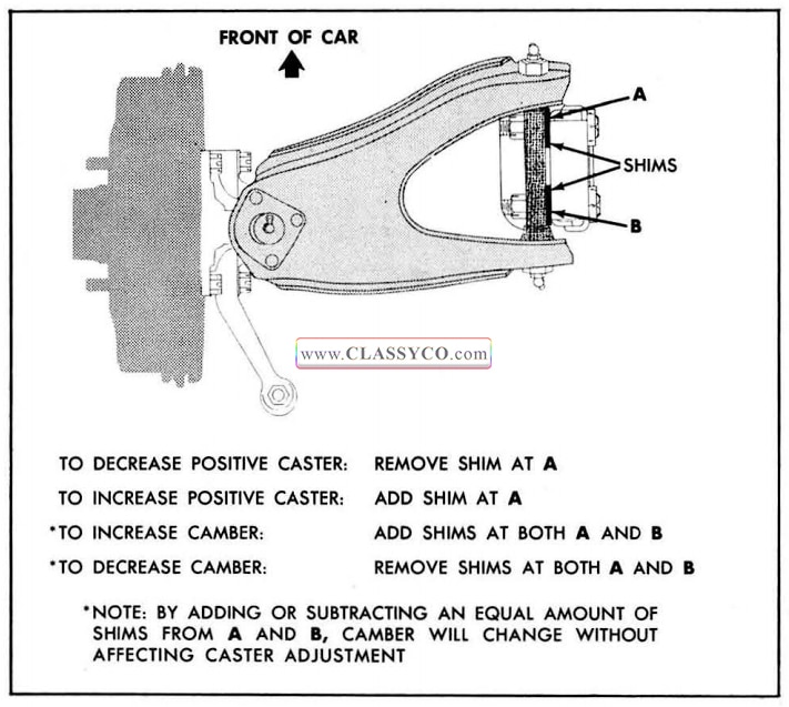
1957 Oldsmobile Caster and Camber Adjustment
In order to remove or install shims, raise car to remove weight from the front wheels then loosen the pivot shaft to frame bolts.
NOTE: Loosen the top and rear fasteners on the fender filler plate aprons to gain access to the pivot shaft bolts.
Refer to the shim chart to determine the amount of shims necessary to correct the adjustment. After the correct number of shims have been in stalled, torque the pivot shaft mounting bolts 85 to 110 ft. lbs. and recheck caster and camber.
1957 Oldsmobile Shim Chart to Determine the Amount of Shims necessary to correct the adjustment
TOE-IN ADJUSTMENT ( 1/16″ to 1/8″)
(Fig. 4-31)
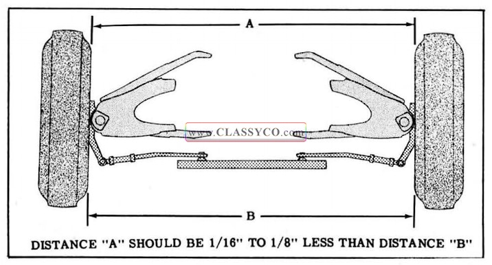
1957 Oldsmobile Front Wheel Toe-In
- Loosen the clamp bolts at each end of the steering tie rod adjustable sleeves.
- With steering wheel set in straight ahead position, turn tie rod adjusting sleeves to obtain the proper toe-in adjustment.
- When adjustment has been completed according to the recommended specifications, and tie rod end ball studs are riding squarely in their seats, position tie rod to relay rod ball studs to the bottom of the slot in the relay. Position inner clamps as shown in Fig. 4-32.
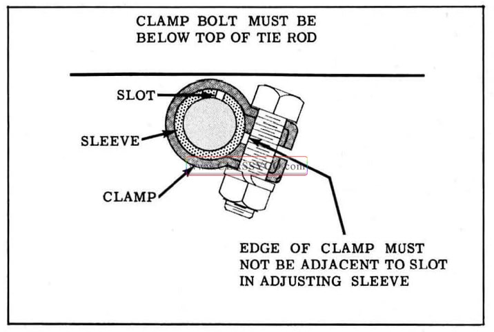
1957 Oldsmobile Tie Rod Clamp Position
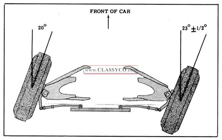
TOE-OUT (STEERING GEOMETRY)
(Fig. 4-33)
Toe-out is the mechanics of keeping the front wheels in proper relative alignment as the wheels are turned right or left. When turning, the wheels go into a toe-out position, (further apart at the front of the tire than they are at the back). This condition increases with the increase of the turn.
Toe-out is checked by turning the wheels to the right or left 20°. The setting of the inside wheel
should be 23° +- ½° on all models. Errors found when checking the inside wheel are usually due to bent plain arms or incorrect caster, camber or toe-in. If error is due to bent plain arm, replacement with new arm should be made. When replacements of this kind are made, it is important that other front end parts are checked and front wheels realigned.
1957 Oldsmobile Front Wheel Toe-Out
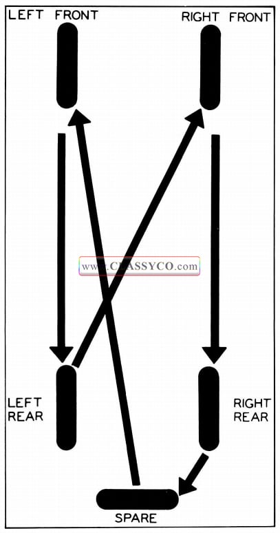
TIRE ROTATION
In order to obtain maximum tire tread life and keep the spare tire from deteriorating due to lack of use, tires should be rotated at 6,000 mile intervals as shown in Fig. 4-34.
1957 Oldsmobile Tire Rotation
DIAGNOSIS
WHEEL BEARING NOISE
Wheel bearing noise may be confused with rear axle noise; however, front wheel bearing noise does not change when comparing “pull” and “coast”. A bad bearing will cause a knock or click approximately every two revolutions of wheel since the bearing rollers do not travel at the same speed as the wheel. To determine which wheel bearing is noisy, hoist the car and spin each wheel while listening at the hub cap.
HARD STEERING
Cause:
- Low or uneven tire pressure.
- Steering gear or connections adjusted too tight.
- Insufficient or incorrect lubricant used.
- Improper caster.
- Upper or lower control arms bent.
- Frame bent or broken.
- Steering knuckle bent.
EXCESSIVE PLAY OR LOOSENESS IN STEERING SYSTEM
Cause:
- Steering gear or connections worn or adjusted too loosely.
- Control arm ball joints worn.
- Front wheel bearings worn or incorrectly adjusted.
- Loose front stabilizer.
ERRATIC STEERING ON APPLICATION OF BRAKE
Cause:
- Low or uneven tire pressure.
- Brakes incorrectly or unevenly adjusted.
- Incorrect or uneven caster.
- Steering knuckle bent.
- Loose steering linkage or suspension.
- Dirt or grease on brake lining.
FRONT WHEEL SHIMMY
Cause:
- Uneven tire pressure.
- Steering connections worn or incorrectly adjusted.
- Front wheel bearings worn or incorrectly adjusted.
- Shock absorbers inoperative or leaking.
- Control arm ball joints worn.
- Toe-in incorrect.
- Incorrect or uneven caster.
- Steering knuckle bent.
- Wheels, tires, or brake drums out of balance.
- Excessive runout of wheels or tires.
CAR PULLS TO ONE SIDE
Cause:
- Low or uneven tire pressure.
- Rear wheels not tracking with front wheels.
- Brakes incorrectly or unevenly adjusted.
- Shock absorbers worn or inoperative.
- Toe-in incorrect.
- Incorrect or uneven caster or camber.
- Rear axle shifted.
- Frame or member bent or broken.
WORN TIRE TREAD EDGES
Cause:
- Improper front end alignment.
- High speed driving on curves.
- Steering knuckle bent.
- Steering plain arm bent.
SCUFFED TIRES
Cause
- Tires improperly inflated.
- Wheels or tires out of true.
- Control arm ball joints worn.
- Toe-in incorrect.
- Uneven caster.
- Incorrect toe-out on turns.
- Steering gear incorrectly adjusted.
- Eccentric or bulged tires.
FRONT OR REAR WHEEL TRAMP
Cause:
- Wheels, tires, or brake drums out of balance.
- Shock absorbers inoperative.
- Loose or worn front wheel bearings.
CAR WANDERS
Cause:
- Low or uneven tire pressure.
- Steering gear or connections worn or adjusted too loosely.
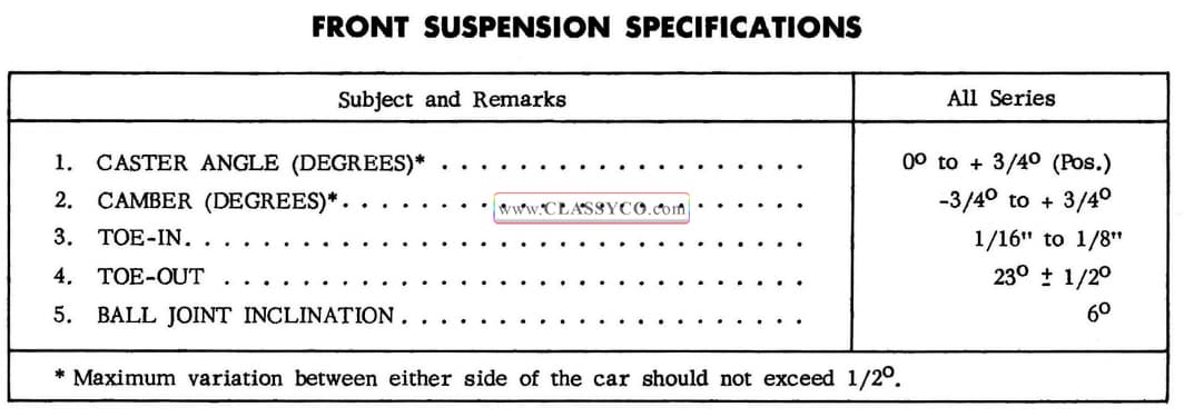
1957 Oldsmobile Front Suspension Specifications
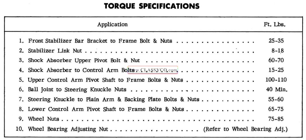
1957 Oldsmobile Torque Specifications
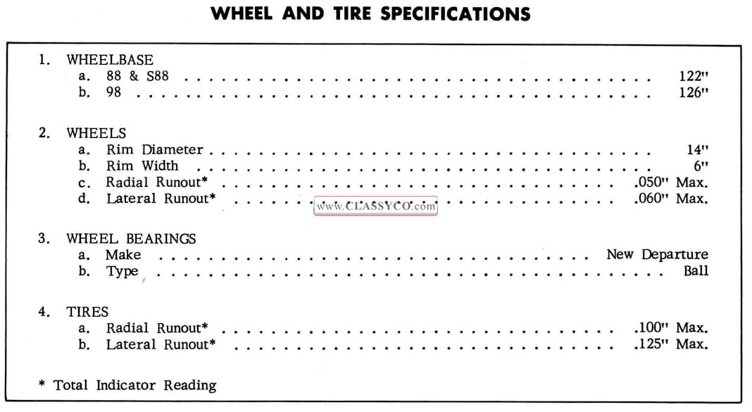
1957 Oldsmobile Wheel and Tire Specifications
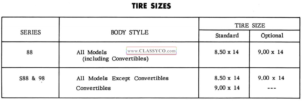
1957 Oldsmobile Tire Sizes
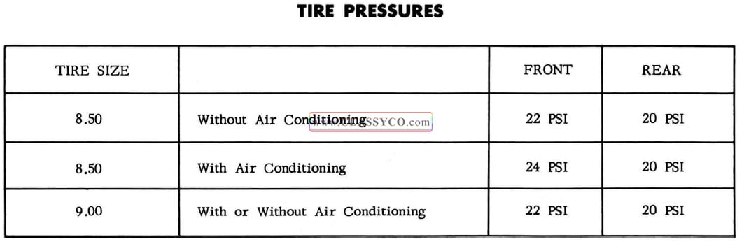
1957 Oldsmobile Tire Pressures
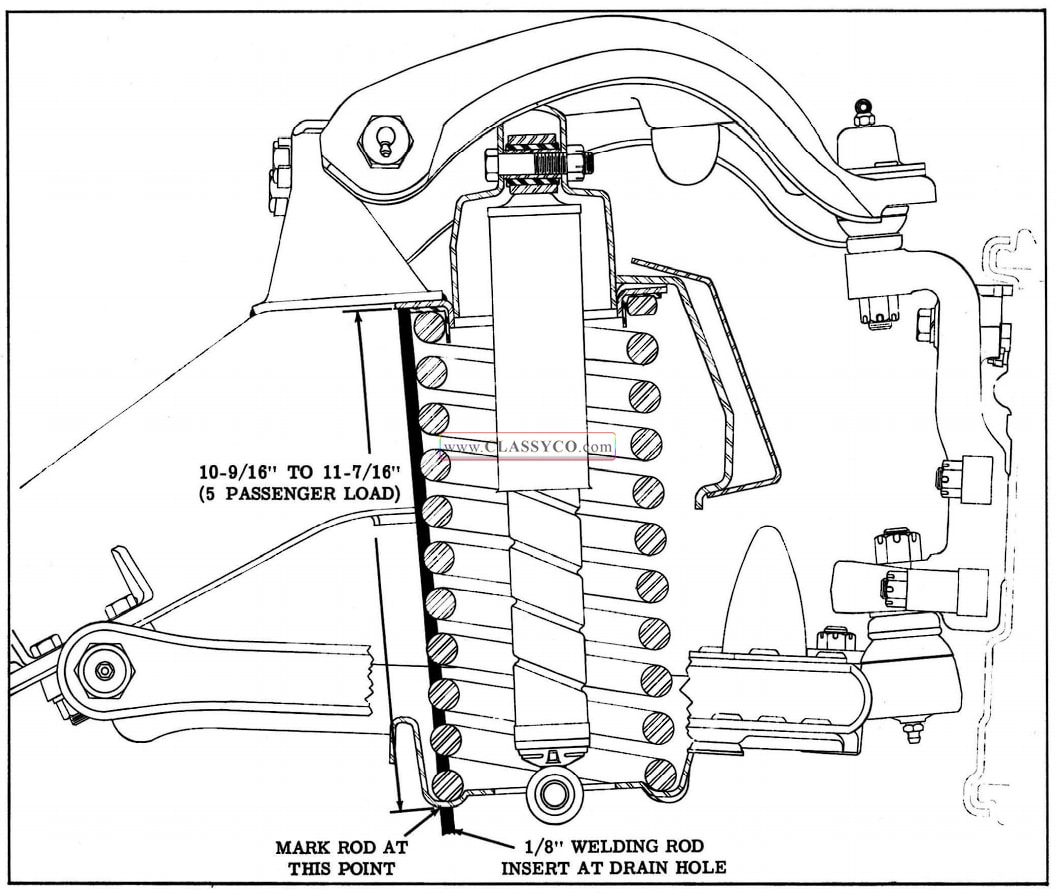
1957 Oldsmobile Spring Carrying Heights 1
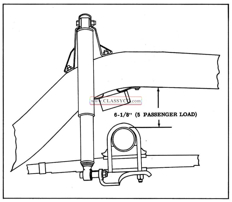
1957 Oldsmobile Spring Carrying Heights 2
1957 Oldsmobile 98 – 4 Door Sedan (DS)