HYDRA-MATIC (JETAWAY)
GENERAL INFORMATION
The new 1957 Jetaway Hydra-Marie transmission is optional on the 88 and Super 88 series and standard on the 98 series. The transmission in corporates a fluid coupling type clutch in the front unit. Sprag clutches (over-running) are used in the front and rear units which result in smoother shifting. An oil cooler is located in the radiator lower tank which prevents the Hydra-Marie fluid from reaching excessively high temperatures when “severe” driving conditions are encountered.
The Hydra-Marie indicator has a “Park” (P) position which is desirable for parking and starting the car when on an incline. The engine can also be started with the selector lever in the “Neutral” (N) position.
TRANSMISSION OPERATION
The transmission offers three selective drive ranges, “D”, “S”, and “L”. In “D” range the transmission starts in first gear and shifts automatically to second, third and fourth gear.
With the selector lever in “S” range the trans mission starts in first gear and shifts to second, then to third and remains in third gear until ap proximately 65-70 M.P.H., regardless of throttle opening. This provides additional acceleration for long hills or traffic driving as well as engine braking power when descending long grades. When car speed reaches approximately 65-70 M.P.H. the transmission automatically shifts to fourth gear. If car speed decreases to approximately 65-70 M.P.H. the transmission will downshift to third gear.
With the selector lever in “L” range the trans mission will shift from first to second and remain in second gear until approximately 15-50 M.P.H. before shifting to third gear. The transmission will then shift to fourth gear at approximately
65-70 M.P.H. As car speed decreases the trans mission will downshift fourth to third and third to second at approximately the same speed at which the upshifts occurred. “L” range is designed for engine braking when descending steep grades. It may also be used to hold the car in second gear for maximum pulling power.
PART THROTTLE DOWNSHIFT
Fourth to Third
A part throttle downshift can be made any time the transmission is in fourth gear and the car speed is below approximately 30 M.P.H. Since this downshift will occur at part throttle opening, the advantage of third gear power is obtained without a wide open throttle. This feature is desirable in traffic conditions where a wide open throttle would be unnecessary.
1957 Oldsmobile Jetaway Hydra-Matic Transmission
FORCED DOWNSHIFTS (Detent)
In “D” range the transmission can be downshifted fourth to third and third to second within set speed ranges.
In “S” range a third to second forced downshift can be made within a set speed range. A warning “feel” on the accelerator pedal makes it possible for the driver to obtain full throttle performance with or without downshift, as desired.
REVERSE
Reverse is accomplished through use of a friction clutch applied by oil pressure and designed for ease in “rocking” the car. A reverse blocker piston prevents movement of the selector lever to reverse position above 10 M.P.H.
PARKING
With the selector lever in the “Park” (P) position, a parking pawl engages with lugs on the reverse planet carrier and locks the output shaft to the transmission case. A detent in the steering column prevents accidental movement of the selector lever to the “Park” (P) position.
TOWING PRECAUTIONS
Whenever it becomes necessary to tow a HydraMatic equipped Oldsmobile, the propeller shaft must be removed or the vehicle towed with the rear wheels off the ground. Damage to the transmission may result unless this practice is followed.
PUSHING CAR TO START ENGINE
To start the engine by pushing the car, move the selector lever to the “Neutral” (N) position and turn on ignition switch. When the car reaches a speed of 25 M.P.H., move the selector to “O” or “S” range position.
MAINTENANCE
The fluid level should be checked every 2,000 miles and should be changed at 25,000 mile intervals. The fluid level should be checked with the engine running at idle speed, the selector in “Park” (P) position, and the car on a level surface. Ap proximately 11 quarts of oil are required to refill a transmission for an oil change. Use only G.M. Hydra-Matic fluid or fluid identified by brand names and the words “Fluid Type A”, plus an Armour Qualification number embossed on top of the can as follows: “AQ-ATF-number”.
ADJUSTMENTS
There is one band used in the Hydra-Matic transmission and it does not require adjustment. The band is used in first and second speeds, “L” range only.
Linkage adjustment is required (See Linkage Adjustment).
1957 Oldsmobile Neutral (Engine Running)
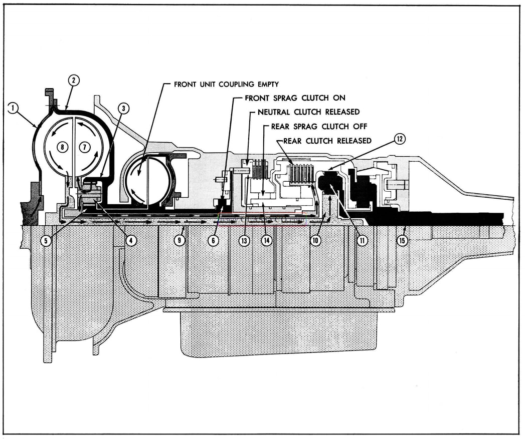
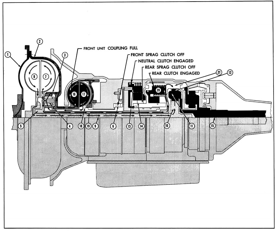
NEUTRAL (ENGINE RUNNING)
FRONT UNIT (IN REDUCTION) Neutral Clutch Rear Unit (Neutral)
Sprag Clutch On Released Sprag Clutch Off
Front Coupling Empty Rear Clutch Off
In neutral, the power flow from the engine is through the flywheel (1) to the torus cover (2) which is bolted to the flywheel. The front unit drive gear (3) is driven by the torus cover, therefore power is transmitted through the cover to the front unit drive gear, through the drive gear to the planet gears (4) causing them to drive around the sun gear (S) which is held stationary by the front sprag clutch (6). Since the planet gears are connected to the drive torus (7) through the planet carrier, the power flow is through the planet gears to the carrier and to the drive torus. The drive torus is turning at less than engine speed due to the reduction of the front unit. The drive torus transmits the power through oil to the driven torus (8) which is splined to the main shaft (9), and through the main shaft to the rear unit sun gear (10) on the main shaft. The rear unit sun gear transmits power to the planet gears (11). The planet gears, turning counterclockwise, drive the rear unit internal gear (12) counter-clockwise. With the neutral clutch (13) released, the external race of the rear sprag (14), connected to the rear unit internal gear, is allowed to turn with the in ternal gear, therefore no power can be transmitted to the output shaft (15).
1957 Oldsmobile First Speed
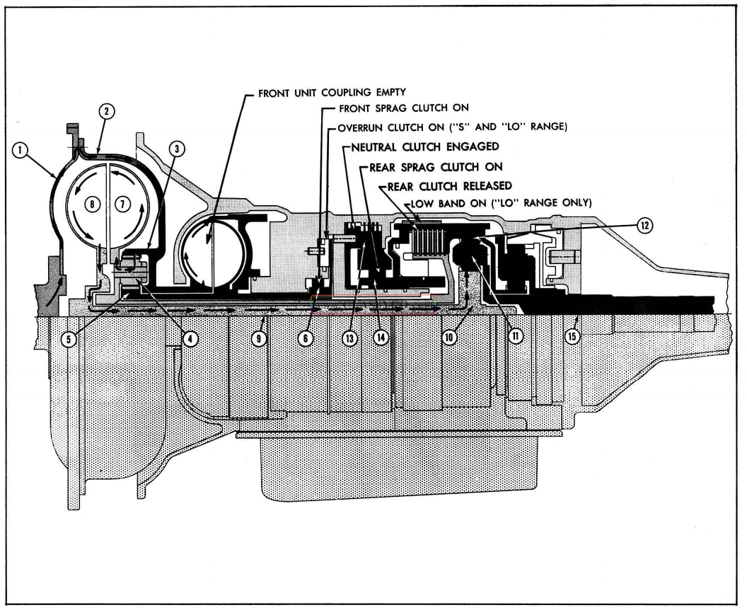
FIRST SPEED (3.96 to 1 Ratio)
FRONT UNIT (IN REDUCTION) NEUTRAL CLUTCH REAR UNIT (IN REDUCTION)
Sprag Clutch On Applied Sprag Clutch On
Front Coupling Empty Rear Clutch Off
In first peed, the front and rear planetary units are in reduction. The power flow is through the flywheel () to the torus cover (2). Since the front unit drivel gear (3) is driven by the torus cover, power is transmitted through the cover to the front unit drive gear, through the drive gear to the planet gears (4), causing them to drive around the sun gear (5) which is held stationary by the front sprag clutch (6). Since the planet gears are connected to the drive torus (7) through the planet carrier, power flow is through the planet gears to the carrier and to the drive torus. The drive torus is turning at less than engine speed due to the reduction of the front unit. The drive torus transmits power through oil to the driven torus (8), splined to the main shaft (9), and through the main. shaft to the rear unit sun gear (10) on the main shaft. The rear unit sun gear transmits power to the planet gears (11) causing them to drive around the rear unit internal gear (12) which is held stationary by the rear sprag clutch (14). The outer race of the rear sprag clutch is held by the neutral clutch (13). The planet gears transmit the power to the planet carrier on the output shaft (15) at reduction.
1957 Oldsmobile Second Speed
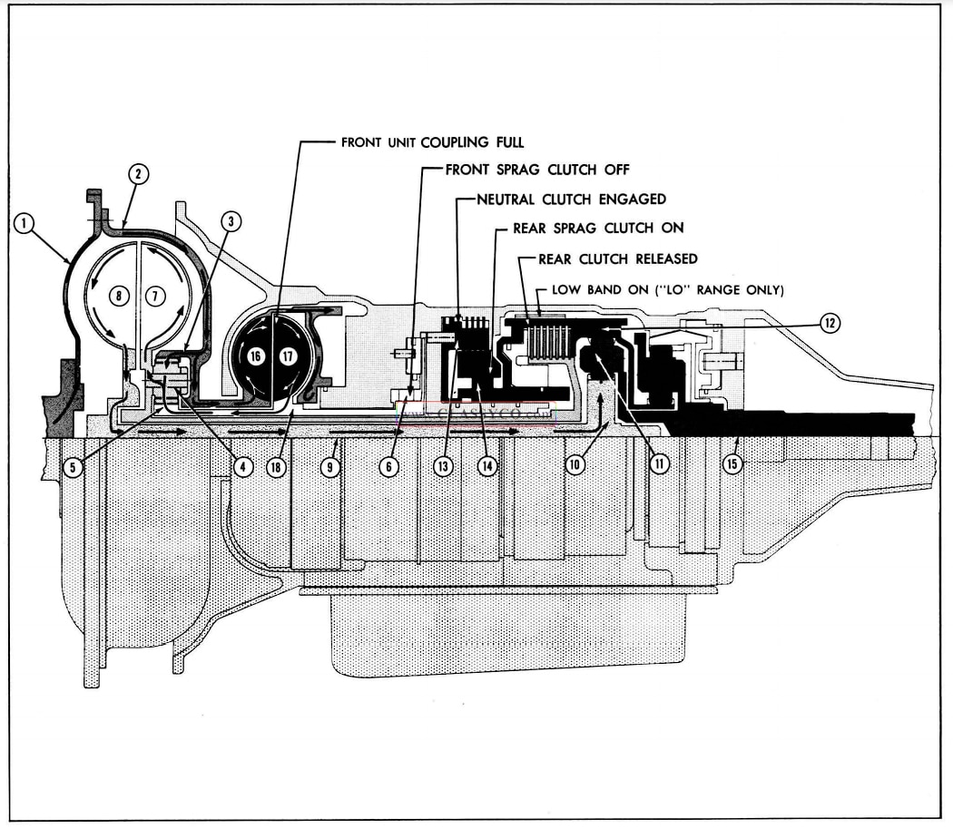
SECOND SPEED (2.55 to 1 Ratio)
FRONT UNIT (DIRECT DRIVE) NEUTRAL CLUTCH REAR UNIT (IN REDUCTION)
Sprag Clutch Off Applied Sprag Clutch On
Coupling Full Rear Clutch Off
In second speed, the front unit is in direct drive and the rear unit is in reduction. The power flow is through the flywheel (1) to the torus cover (2). The torus cover is connected to the front unit drive gear (3) and the drive torus (16) of the front unit coupling, so the power flow divides at the front unit drive gear. Since the front unit coupling is full in second speed, power is transmitted from the drive torus through oil to the driven torus (17) and to the front unit sun gear (5). With the front unit drive gear locked through oil in the front unit coupling to the front unit sun gear the power is transmitted to the planet gears (4) at engine speed. The planet gears transmit power to the carrier attached to the drive torus (7). The drive torus transmits the power through oil to the driven torus (8) splined to the main shaft (9), then through the main shaft to the rear unit sun gear (10) on the main shaft. The rear unit sun gear transmits power to the planet gears (11) causing them to drive around the rear unit internal gear (12), which is held stationary by the rear sprag clutch (14). The outer race of the rear sprag clutch is held by the neutral clutch (13). The planet gears transmit the power to the planet carrier on the output shaft (15) at reduction.
1957 Oldsmobile Third Speed
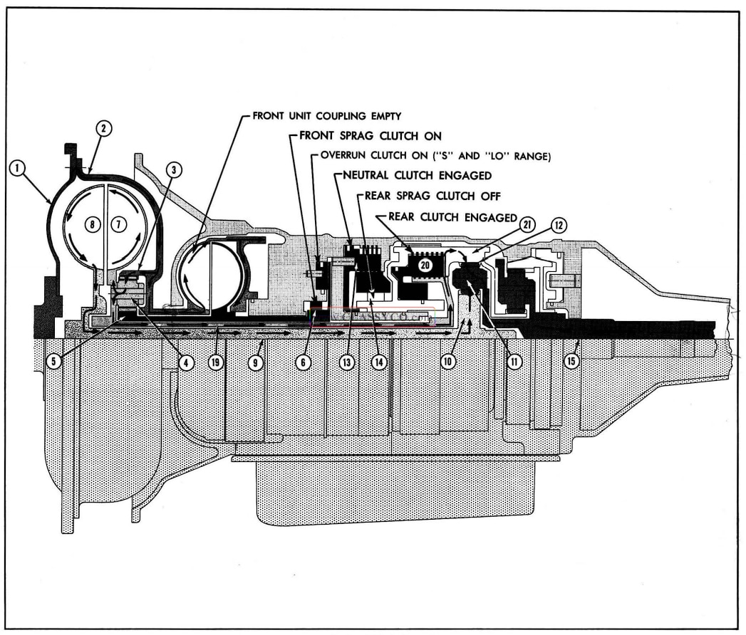
THIRD SPEED (1.55 to 1 Ratio)
FRONT UNIT (IN REDUCTION) NEUTRAL CLUTCH REAR UNIT (DIRECT DRIVE)
Sprag Clutch On Applied Sprag Clutch Off
Front Coupling Empty Rear Clutch On
In third speed, the front unit is in reduction and the rear unit is in direct drive. The power flow is through the flywheel (1) to the torus cover (2). Since the front unit drive gear (3) is driven by the torus cover, power is transmitted through the cover to the front unit drive gear, and through the drive gear to the planet gears (4) causing them to drive around the sun gear (5) which is held stationary by the front sprag clutch (6). Since the planet gears are connected to the drive torus (7) through the planet carrier, the power flow is through the planet gears to the carrier and to the drive torus. The drive torus is turning at less than engine speed due to the reduction of the front unit. Approximately 40% of the torque is trans mitted from the drive torus through oil to the driven torus (8) splined to the main shaft (9), then through the main shaft to the rear unit sun gear (10) on the main shaft. The remainder (approximately 60%) of the torque is transmitted from the drive torus to the intermediate shaft (19), then through the rear clutch plate (20) to the rear unit internal gear (12) attached to the rear unit drum (21). This 60% (mechanical)” joins the 40% from the fluid coupling at the planet gears and the resultant is transmitted to the planet carrier on the output shaft (15).
1957 Oldsmobile Fourth Speed
FOURTH SPEED (Direct Drive)
FRONT UNIT (DIRECT DRIVE) NEUTRAL CLUTCH REAR UNIT (DIRECT DRIVE)
Sprag Clutch Off Applied Sprag Clutch Off
Front Coupling Full Rear Clutch On
In fourth speed, the front and rear units are in direct drive. The power flow is through the fly wheel (1) to the torus cover (2). The torus cover is connected to the front unit drive gear (3) and the drive torus of the front unit coupling (16), so the power flow divides at the front unit drive gear. Since the front unit coupling is full in fourth speed, power is transmitted from the front unit coupling drive torus through oil to the driven torus (17) and to the front unit sun gear (5). With the front unit drive gear locked through oil in the front coupling to the front unit sun gear, the power is transmitted to the planet gears (4) at engine speed. The planet gears transmit power to the carrier attached to the drive torus (7). Approximately 40% of the torque is transmitted from the drive torus through oil to the driven torus (8) splined to the main shaft (9) then through the main shaft to the rear unit sun gear (10) on the main shaft. The remainder (ap proximately 60%) of the torque is transmitted from the drive torus to the intermediate shaft, (19) then through the rear clutch plates (20) to the rear unit internal gear (12) attached to the rear unit drum (21). This 60% (mechanical) joins the 40% from the fluid coupling at the planet gears and the resultant is transmitted to the planet carrier on the output shaft (15).
1957 Oldsmobile Reverse
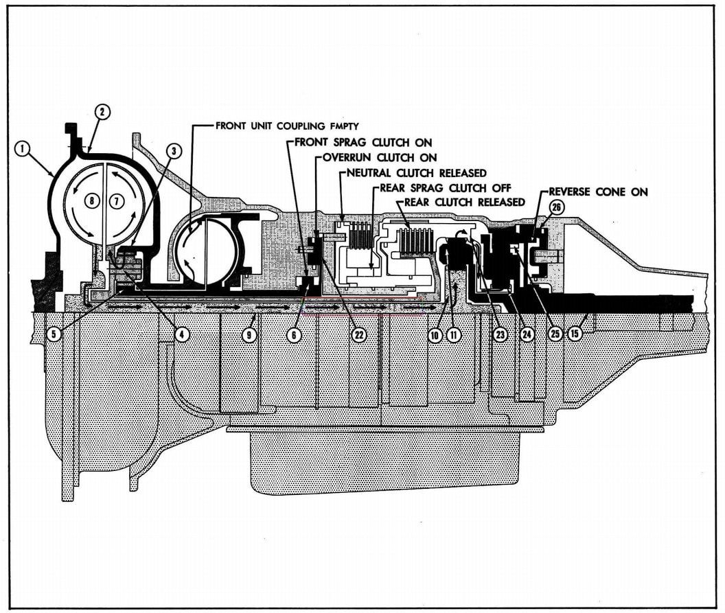
REVERSE (3.74 to 1 Ratio)
FRONT UNIT (IN REDUCTION) NEUTRAL CLUTCH REAR UNIT (IN REDUCTION) REVERSE UNIT (IN REDUCTION)
Sprag Clutch On Off Sprag Clutch Off Cone Clutch On
Overrun Clutch On
Coupling Empty Rear Clutch Off
In reverse, the front unit, rear unit and reverse unit are in reduction. The power flow is through the flywheel (1) to the torus cover (2). Since the front unit drive gear (3) is driven by the torus cover, power is transmitted through the cover to the front unit drive gear, through the drive gear to the planet gears (4) causing them to drive around the sun gear (5) which is held stationary by the front sprag clutch (6). Since the planet gears are connected to the drive torus (7) through the planet carrier, the power flow is through the planet gears to the carrier and to the drive torus. The drive torus is turning at less than engine speed due to the reduction of the front unit. The drive torus transmits the power through oil to the driven torus (8), (splined to the main shaft (9), and through the main shaft to the rear unit sun gear (10) on the main shaft. The rear unit sun gear transmits power to the planet gears (11). The neutral clutch (13) and rear clutch (20) are off and with the rear planet gears acting as idlers, the rear internal gear (12) and drum (21) turn counter clockwise. The internal gear, through the reverse drive flange (23), drives the reverse sun gear (24) of the reverse planetary unit. The reverse in ternal gear (25) is held by the reverse cone clutch (26) and the power is transmitted through the re verse planet carrier to the output shaft (15).
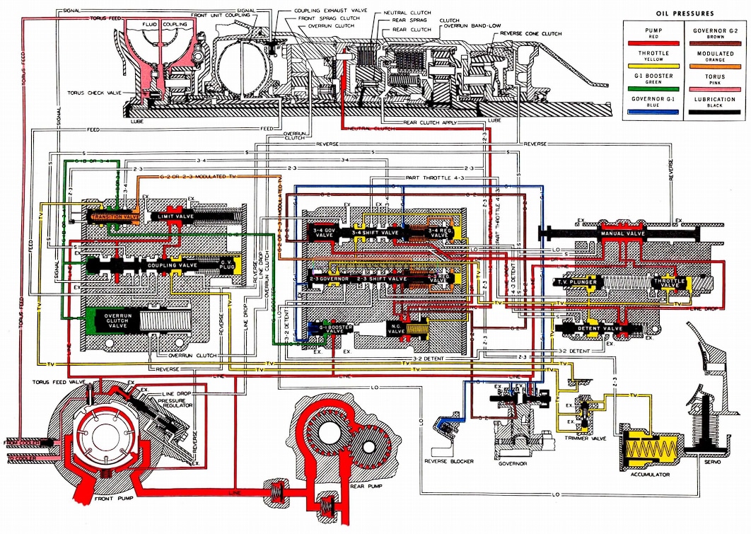
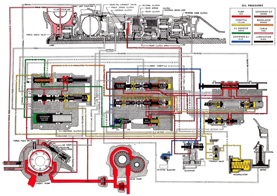
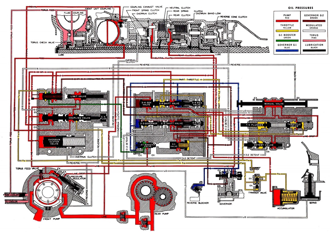
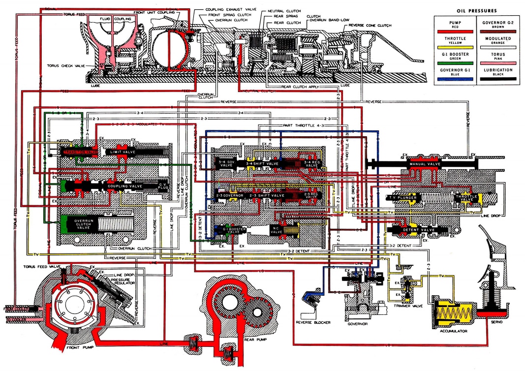
HYDRAULIC OIL CIRCUIT (Fig. 3-8)
VALVES AND THEIR FUNCTION
NEUTRAL CLUTCH VALVE
A neutral clutch valve has been added to the 1957 Jetaway transmission. The new valve will regulate neutral clutch apply oil pressure in relation to the holding effort required through all throttle openings. This is accomplished by the use of T.V. pressure and provides a smoother application of the neutral clutch when shifting from “N” to “D”.
LIMIT VALVE
The limit valve prevents a sudden drop in line pressure when the front unit coupling fills. It also acts as a pressure relief valve to protect the system from excessive pressure. Pump pressure on the large diameter of the valve will move the valve to the right and open the passage to the coupling valve feed oil passage. The larger spring serves as the pressure relief.
COUPLING VALVE
The new two piece coupling valve is in the oil circuit to control the filling and emptying of the front unit coupling. It is held in the closed position in the forward speeds by spring pressure and T.V. pressure and in reverse position by spring pressure, T.V. pressure and reverse oil pressure. The coupling valve opens when G-1 booster pressure builds up high enough to overcome the combined spring pressure and throttle pressure. The valve will not open in reverse. When the valve opens main line pressure is directed into the signal oil passage to close the 2 exhaust valves in the front unit coupling. Main line pressure thru the limit valve is also directed into the feed passage to fill the front unit coupling. The T.V. passage to the end of the valve is also cut off and the pressure on the plug is allowed to exhaust out the reverse passage. This prevents throttle downshift. “S” range oil is directed through the valve to apply the overrun front clutch in third and first speeds, “S” range and “L” range. The coupling valve closes the “S” range oil passage to the overrun front clutch in second and fourth, “S” range and “L” range. When the coupling valve moves to the left, it cuts off main line pressure to the signal oil and feed oil passages. The exhaust valves in the front unit coupling will open and oil will be thrown from the front unit coupling by centrifugal force.
OVERRUN CLUTCH VALVE
The new overrun clutch valve is positioned to the right by G-1 booster pressure in “D” and “R “. In “Drive” range the overrun clutch apply passage is open to exhaust through the reverse passage at the manual valve. In “Reverse”, oil is directed from the manual valve to the overrun clutch piston to apply the clutch.
In “S” and “L” range pump pressure is directed from manual valve through the coupling valve, in first and third, to the right end of the overrun clutch valve.
Pump pressure and spring pressure slowly move the overrun clutch valve to the left against exhausting 3-4 oil or G-1 booster pressure and thus open the passage to the overrun clutch to delay application of the clutch. This delay in applying the overrun clutch is to allow the front unit coupling to empty and front sprag clutch to engage, resulting in a smooth downshift 4-3 when moving the selector lever from “D” to “S” range. In second and fourth speeds, the coupling valve cuts off the pump pressure to the overrun clutch valve and G-1 booster pressure moves the valve to the right. The overrun clutch apply pressure then exhausts through the reverse passage and the overrun clutch is released by spring force. In reverse, the spring holds the valve to the left to prevent application of the overrun clutch under a speed of approximately 5 M.P.H. At this point, G-1 booster pressure is sufficient to move the valve to the right allowing reverse oil to apply the overrun clutch.
TRANSITION VALVE
The transition valve controls the front unit on the 2-3 upshift. When the 2-3 shift valve opens, 2-3 oil pressure is directed to one end of the transition valve which moves it to the right against combined G-2 pressure and spring force. Movement of the valve cuts off G-1 booster pressure to the coupling valve and exhausts it through the 3-4 valve. The orifice in the 2-3 passage to the transition valve is to aid in timing the front unit with the rear unit during the 2-3 shift.
DETENT VALVE
Main line pressure from the manual valve is directed through the detent valve to the 3-4 governor valve. This pressure has no action on the detent valve, and the passage to the 3-4 governor valve is closed when the detent valve has been pushed to the left. “S” range oil is directed through the detent valve to the 3-4 shift valve to hold the transmission in third speed. The detent valve is mechanically opened by linkage. It is returned to the closed position by spring force on the end of the valve. The valve is in the circuit to make the 4-3 and 3-2 detent downshifts. When the accelerator pedal has been depressed all the way, the valve will be positioned to the left. T.V. pressure at the detent valve will then be directed to the 2-3 and 3-4 shift valves. At car speeds below 65 M.P.H. the 4-3 shift valve will close for a 4-3 downshift, and at speeds below 20 M.P.H. the 2-3 shift valve will close for a 3-2 downshift.
PUMP PRESSURE
The first requirement of a hydraulic control system is a source of oil pressure. Oil pressure for the Hydra-Matic transmission is supplied by two oil pumps. One is at the front of the trans mission driven by the engine, the other at the rear, driven by the transmission output shaft. The front pump operates whenever the engine is running; the rear pump operates whenever the car is in forward motion.
The front pump is of the vane type and consists of 7 vanes rotated within a movable slide by a rotor. Variable output is achieved through the movable slide. A priming spring holds the slide up to deliver maximum output to quickly attain regulated pressure in the control system when the engine is started. The pressure regulator will then adjust the position of the slide so that only the amount of oil needed is pumped. Main line pressure operates on the end of the pressure regulator and tends to move it downward. When the pressure regulator is in the upward position, oil is directed to hold the slide up for maximum out put. Oil is directed to the opposite side of the slide when the pressure regulator is forced down and the volumn output of the pump will be de creased to the amount required to maintain regulated pressure.
The torus feed valve controls the flow of oil to the fluid coupling, the valve is held against the slide by the spring. The valve closes the oil pass age to the fluid coupling until oil pressure moves the slide toward the priming springs. The valve follows the slide and opens to direct oil through the oil cooler in the radiator lower tank, through the fluid coupling and lubrication system. A ball check is provided to by-pass the cooler in the event the cooler becomes plugged. The limit valve in the front clutch valve body protects the system against excessive pressures. Both oil pumps de liver oil at regulated pressure (controlled by front pump) when the car is driven forward. The 2 check valves in the rear pump allow oil to circulate through the rear pump body in reverse.
THROTTLE PRESSURE
The manual body has been changed to allow pump oil to feed the throttle valve in “N”, “D”, “S” and “L” ranges. Feed is cut off at the manual valve in “P” and “R”.
Throttle valve pressure originates at the throttle valve and varies according to carburetor throttle opening by means of linkage from the accelerator pedal. As the accelerator pedal is depressed, linkage to a lever on the side of the transmission moves the throttle valve plunger. Plunger movement opens the throttle valve through spring force, and oil from the pump then flows through an opening at the throttle valve. This oil under pressure acts on the end of the throttle valve to oppose the throttle valve spring force which opened the valve. In this manner the throttle valve be comes a balanced valve; balanced between spring force and throttle pressure. As a result of this action throttle pressure varies with accelerator pedal position from zero pressure at closed throttle to full line pressure at full throttle. Throttle pressure is directed to a land on the throttle valve plunger to assist in moving the plunger which gives a lighter “feel” to the accelerator pedal. This pressure cannot move the plunger without assistance from the accelerator linkage.
Throttle valve pressure is directed to the 2-3 and 3-4 regulator valves where it is modulated. Throttle valve pressure acts against the end of these valves, and due to their design the pressure of the oil passing the valves is reduced. It is therefore called modulated throttle valve pressure. This pressure assists the 2-3 and 3-4 shift valve springs in opposing governor pressures.
Throttle valve pressure is directed to the coupling valve plug to assist the coupling valve springs in opposing G-1 booster pressure.
Throttle valve pressure is directed to the transition valve when in detent position for a 3-2 downshift to prevent a 3-1-2 downshift by properly timing the front and rear unit change.
Throttle pressure is directed to the accumulator to absorb the shock of the rear clutch apply oil pressure.
GOVERNOR PRESSURE
A centrifugal governor driven by the rear pump supplies two governor pressures. G-1 is supplied from the governor valve having the large weight. G-2 is supplied from the governor valve having no weight. These two pressures vary with car speed, however, G-1 increases at a faster rate than G-2 pressure because of the large weight.
The G-1 valve and G-1 booster valve are spring loaded to assist in opening the valves to give initial governor pressures when the engine is running. This is to provide a higher G-1 pressure and G-1 booster pressure at low car speeds. The G-1 valve is a balanced valve, balanced between G-1 pressure and centrifugal force assisted by spring force. The G-2 valve is a balanced valve, balanced between G-2 pressure and centrifugal force. Pump pressure is the supply for G-1 pressure and G-1 pressure is the supply for G-2 pressure.
G-1 pressure is used to open the G-1 booster valve, and is also used to assist G-2 pressure in opening the 2-3 and 3-4 shift valves. G-2 pressure is used on the transition valve to help control the 2-3 shift.
G-1 BOOSTER VALVE PRESSURE
A new longer G-1 booster valve and spring are used in the 1957 Hydra-Matic. G-1 booster pressure originates at the G-1 booster valve. G-1 pressure and spring pressure work on the larger diameter end of the valve, move it to the right al lowing main line pressure to feed into the center area of the valve. As G-1 booster pressure builds up in the center of the valve, it moves the valve back to the closed position cutting off the main line pressure. Since the G-1 booster pressure must force the valve closed against G-1 pressure, and has less area of the valve to work on, booster pressure will be higher than G-1. The G-1 booster valve is a balanced valve, balanced between G-1 and G-1 booster pressure. G-1 booster pressure increases with car speed until it reaches main line pressure. As car speed decreases, G-1 booster pressure forces the valve further to the left against G-1 pressure and allows G-1 booster pressure to enter the G-1 passage where it is regulated at the G-1 valve.
G-1 booster pressure is directed through the transition valve to one end of the coupling valve. When G-1 booster pressure on the end of the coupling valve becomes high enough, depending on car speed, to overcome the spring force and T.V. pressure on the other end of the coupling valve it will move the valve for the 1-2 upshift. G-1 booster pressure is also used to control the over run clutch valve as previously mentioned.
REAR CLUTCH PISTON
The rear clutch piston has been modified in the 1957 Hydra-Matic Transmission and now incorporates a.040 hole in the surface of the piston.
ACCUMULATOR ASSEMBLY
The 1957 transmission uses an accumulator assembly of an improved design to provide for the increased engine torque and a smoother 2-3 shift. T.V. pressure is directed to the rear of the accumulator piston to assist the spring. However, a passage has been added to the side of this piston to allow T.V. oil to enter the entire accumulator body and further assist the spring. The accumulator assembly uses regulated T.V. pressure plus a spring to cushion the 2-3 oil to provide for a smooth application of the rear clutch under all throttle conditions. The trimmer valve has been redesigned and an accumulator T.V. plug and spring have been added.
1957 Oldsmobile Oil Pressures
NEUTRAL-ENGINE NOT RUNNING
Car Standing
With both pumps inoperative there is no oil pressure and the front unit coupling is empty. The front and rear sprag clutches are off, the overrun clutch, the neutral clutch, the rear clutch, reverse clutch, and the low band are off. If the selector lever is moved to the “P’ position, the parking pawl will engage the parking gear and lock the output shaft for parking.
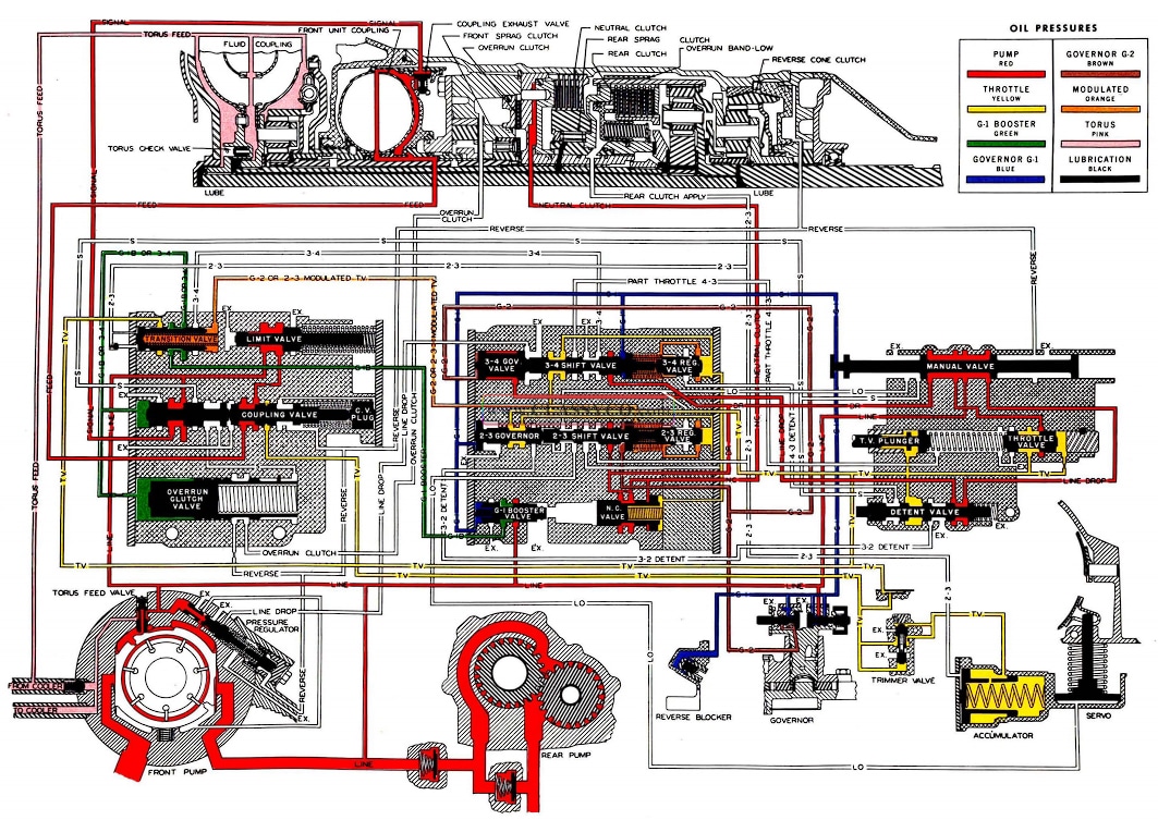
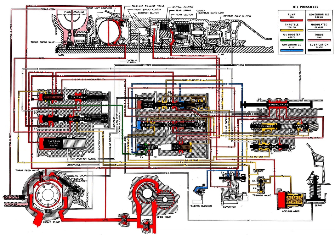
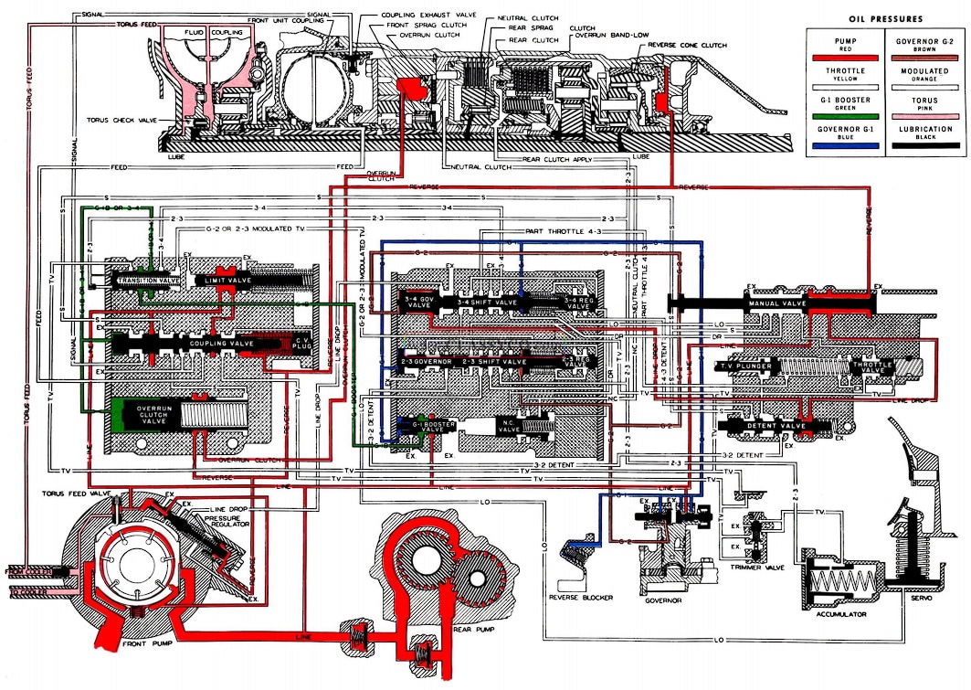
NEUTRAL-ENGINE RUNNING
The front unit is in reduction, but the neutral clutch is off, so drive cannot be transmitted to the output shaft. In neutral oil pressure is required for lubrication only, however when the engine is started, the front pump directs oil to:
- The Pressure Regulator
- The G-1 Booster Valve
- The G-1 Valve of the Governor
- The Coupling Valve
- The Limit Valve
- The manual valve, through which oil is directed to:
The Throttle Valve
The Detent Valve
The 3-4 Governor Valve
As pressure is built up in the line, the pressure regulator causes the pump slide to move toward the center of the pump, opening the torus feed valve allowing oil to be directed through the cooler to fill the fluid coupling and into the transmission for lubrication.
When pump pressure builds up to approximately 55 P.S.I., the limit valve opens against spring pressure to allow line pressure to rest on the coupling valve.
Because the G-1 governor valve is a balanced valve and is held open by spring pressure, main line pressure is directed through it where it be comes regulated as G-1 pressure. G-1 pressure is then directed to:
- The G-2 Valve of the Governor
- The Reverse Blocker Piston
- The 3-4 Shift Valve
- The 2-3 Governor Valve
- The G-1 booster valve, which regulates G-1 booster pressure which is directed to the coupling valve and overrun clutch valve.
1957 Oldsmobile Neutral (Engine Running) (2)
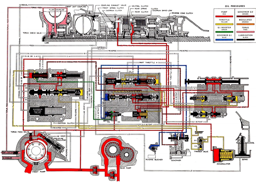
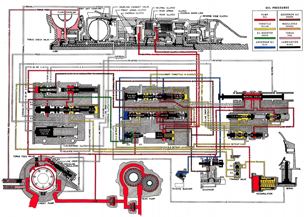
FIRST GEAR-“D”
Front and rear sprag clutches and the neutral clutch must be on. With the front unit coupling empty and the rear clutch released the transmission will be in first gear. (The overrun clutch and low band released in Drive range}.
The manual valve in the “D” position directs oil to:
- The 3-4 Shift Valve
- The 2-3 Shift Valve
- The Neutral Clutch Valve, through which oil is directed to apply:
- The Neutral Clutch
With the neutral clutch and front and rear sprags applied, both units are in reduction and the transmission is in first.
The oil directed to the 2-3 and 3-4 shift valves, and through the detent valve to the 3-4 governor valve has no function at this time.
Governor pressures increase as car speed in creases. G-1 pressure acting on the G-1 booster valve allows G-1 booster pressure to be directed through the transition valve to the coupling valve and the overrun clutch valve. G-1 also applies the reverse blocker piston preventing reverse engagement at speeds above 10 M.P.H.
Increased car speed will open the G-2 governor valve so that G-2 pressure is directed to the 2-3 shift valve and the 3-4 governor valve.
As the throttle is opened, throttle pressure is directed to:
- The Detent Valve
- The 2-3 Regulator Valve
- The 3-4 Regulator Valve
- The Coupling Valve Plug
- The Transition Valve
- The Neutral Clutch Valve
- The Trimmer Valve where T.V. pressure is regulated to the accumulator
T.V. pressure to the neutral clutch valve allows a firm but smooth apply of the neutral clutch, when the selector lever is placed in “D” position.
Modulated T.V. is directed to the 2-3, 3-4 shift valves and transition valve.
1957 Oldsmobile First Gear D
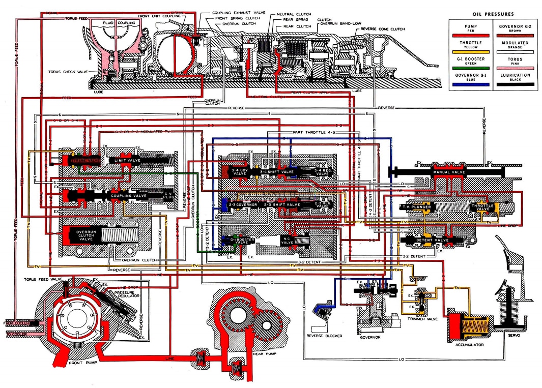
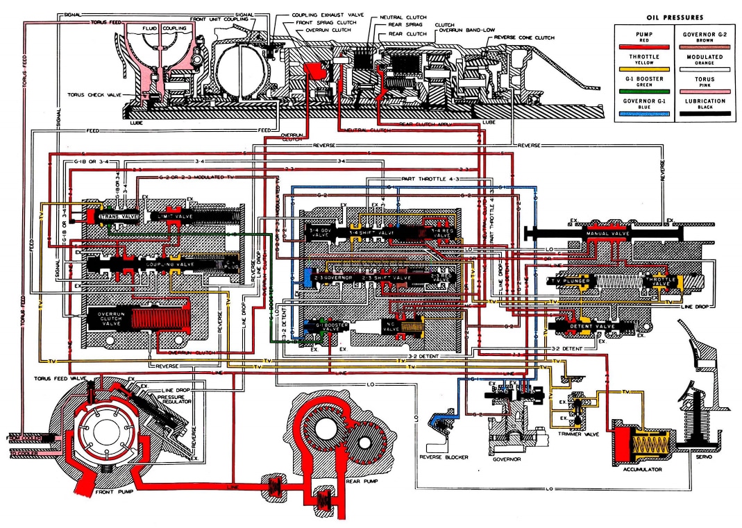
1-2 UPSHIFT AND SECOND GEAR-“D”
FRONT COUPLING FULL AND REAR SPRAG ON
As car speed in first gear increases, G-1 booster pressure opens the coupling valve against T.V. pressure and/or spring pressure. Opening the coupling valve allows signal oil to close the 2 exhaust valves in the front coupling. Main line pressure through the limit valve is free to pass through the coupling valve to fill the front unit coupling. When the front unit coupling fills, the front unit will be in direct drive, and the transmission is now in second gear.
Throttle pressure on the coupling valve and plug is exhausted through the reverse passage and out at the manual valve.
Regulated T.V. pressure in the accumulator has no effect at this time.
1957 Oldsmobile Second Gear D
2-3 UPSHIFT AND THIRD GEAR-“D”
FRONT SPRAG CLUTCH ON
REAR CLUTCH APPLIED
When the car speed increases such that the G-1 pressure on the 2-3 governor valve and G-2 pressure on the 2-3 shift valve is sufficient to overcome the force of the modulated T.V. pressure and shift valve springs, the 2-3 shift valve will open.
As the 2-3 shift valve opens main line pressure is directed to:
- The Rear Clutch – to apply it
- The accumulator – to cushion the clutch apply.
- The transition valve – to cut off G-1 booster pressure to the coupling exhaust valves.
With the transition valve moved, G-1 booster pressure is exhausted through the 3-4 shift valve allowing the coupling valve to close, exhausting the signal oil. This in turn lets the spring loaded coupling exhaust valves open.
T.V. pressure on the 2-3 regulator valve is exhausted at the detent valve.
The trimmer valve regulates T.V. pressure entering the accumulator for firm but smooth rear clutch application regardless of throttle position.
As the front coupling empties, its driven member stops on the front sprag, putting the front unit in reduction. The rear clutch is applied placing the rear unit in direct drive and the transmission is in third gear.
1957 Oldsmobile Third Gear D
3-4 UPSHIFT AND FOURTH GEAR-“D”
FRONT UNIT COUPLING FULL
REAR CLUTCH APPLIED
When the car reaches sufficient speed, G-1 pressure on the 3-4 shift valve and G-2 pressure on the 3-4 Governor plug over- comes the force of spring pressure and modulated T.V. pressure to open the 3-4 shift valve. Opening the 3-4 shift valve allows main line pressure from the manual valve to be directed through the 3-4 shift valve and transition valve, to move the coupling valve against spring pressure and T.V. pressure. Main line pressure now is directed through:
- The coupling valve – to close the coupling exhaust valves (signal oil).
- The coupling valve to fill the front unit coupling (feed oil).
The change is the same as the 1-2 upshift, except that line pressure from the 3-4 shift valve opened the coupling valve instead of G-1 booster pressure.
With the front and rear units now in direct drive the transmission is in Fourth Gear.
When the 3-4 governor valve opens with the 3-4 shift valve, main line pressure is also directed through the “line drop passage” to the pressure regulator, where main line pressure is reduced in fourth gear, thereby lowering horsepower requirements.
1957 Oldsmobile Fourth Gear D
4-3 PART THROTTLE DOWNSHIFT
A 4-3 part throttle downshift can be made any time the transmission is in fourth gear and the car speed is below approximately 30 M.P.H. This is desirable in traffic because the transmission can be downshifted to third gear for faster pickup without a wide open throttle. The part throttle downshift is obtained in the following manner:
When the transmission is in fourth gear and the accelerator is depressed approximately 1/3 down, throttle pressure on the plunger is directed through the 3-4 shift valve to the regulator valve. Throttle pressure and spring force on the regulator valve will close the valve and the transmission will be in third gear. When the shift valve closes, throttle pressure from the plunger will be cut off and throttle pressure from the throttle valve will hold the shift valve closed until governor pressures can increase enough to open the shift valve again for fourth gear. If pressure on the accelerator is relaxed enough then the governor pressures will open the shift valve immediately.
1957 Oldsmobile 4-3 Part Throttle Downshift
FOURTH GEAR-“D”
DETENT POSITIONED FOR FORCED
4-3 DOWNSHIFT
It may be desirable to downshift the transmission from fourth to third at a speed higher than the part throttle downshift would occur. This downshift can be made up to speeds of approximately 65-70 M.P.H. by pressing the accelerator pedal all the way down. As the throttle lever contacts the detent valve, the increased resistance due to the detent valve spring will be felt. This resistance is to warn the driver and prevents an accidental downshift. If additional foot pressure is used, the detent valve moves to the right and the following will occur:
Detent oil is directed to the 3-4 shift valve which will close the valve against governor pressures and the transmission will downshift from fourth to third gear.
When the detent valve moves to the right it cuts off the main line passage through the 3-4 governor valve to the pressure regulator valve. Pump pressure immediately builds up to maximum operating pressure for the fourth to third downshift.
Detent oil also is directed to the 2-3 regulator valve and the 3-2 downshift will occur at speeds below 20 M.P.H.
1957 Oldsmobile Fourth Gear D (Forced 4-3 Downshift Detent Position)
THIRD GEAR-“D”
FORCED 3-2 DOWNSHIFT DRENT POSITION
Below 20 M.P.H. a forced downshift to second gear may be obtained. Pressing the accelerator pedal to the floor will move the detent valve to the right and the following will occur:
Throttle pressure will be directed from the throttle valve through the detent valve to the 2-3 regulator valve.
Detent oil assisted by spring force will over come the governor pressures and the valve will close placing the transmission in second gear.
1957 Oldsmobile Third Gear D (Forced 3- 2 Downshift Detent Position)
THIRD GEAR-“S” RANGE
“S” range is provided in order to keep the car operating in third gear over a large portion of the driving range. This is of particular advantage for engine braking, for hilly driving, or acceleration in heavy traffic with part throttle. Placing the selector lever in “S” range causes the following operations to occur:
The manual valve directs “S” range oil (main line pressure) through the detent valve around the 3-4 regulator plug and into the area between the 3-4 regulator plug and the 3-4 shift valve. With “S” range oil assisting the 3-4 shift valve spring, the 3-4 upshift will be delayed until G-1 and G-2 have built up enough pressure to overcome them.
Since the front sprag will overrun while coasting, “S” range oil from the manual valve is directed through the coupling valve to one end of the overrun clutch valve and moves the overrun clutch valve (with delayed action) to the left against exhausting 3-4 oil. Movement of the valve opens a passage to the overrun front clutch and “S” range oil applies the clutch, thereby holding the front unit sun gear to provide engine braking. The overrun front clutch is effective in first and third “S” range.
1957 Oldsmobile Third Gear S Range
FIRST GEAR-“L” RANGE
First gear “L” range is the same as first gear drive range except that the manual valve directs “L” range oil through the 2-3 shift valve to the low band servo to apply the band for first and second gear. The low band is necessary for engine braking since the rear sprag is not effective when coasting. The “S” range passage is also open so the overrun clutch is applied for engine braking.
1-2 UPSHIR AND SECOND GEAR “L” RANGE
The 1-2 upshift and second gear is the same as in “S” range except that the low band will remain applied.
2-3 UPSHIR AND THIRD GEAR “L” RANGE
The 2-3 upshift and third gear will occur at approximately 45-50 M.P.H. and is accomplished in the following manner. When G-1 and G-2 pressure has increased enough to overcome pump pressure on the 2-3 shift valve from the low range passage and spring force, the shift valve will open. Movement of the shift valve will direct pump pressure through the 2-3 passage to apply the rear clutch and also to the transition valve to cut off G-1 booster pressure to the coupling valve the same as it does in 2-3 upshift “D” range. Pressure to the low band servo is also cut off and the band is released by spring force, oil from the servo is exhausted at the 2-3 shift valve*. “L” range oil pressure remains on the 2-3 shift valve so that if car speed decreases the transmission will downshift to second gear approximately the same speed as the upshift occured.
*Movement of the shift valve cut off “L” range oil to the transition valve which allowed 2-3 oil to move it to the right to cut off G-1 booster to the coupling valve. G-1 and G-2 on the 2-3 governor valve and shift valve will prevent a throttle down shift to second gear at car speeds above 45-50 M.P.H.
3-4 upshift and fourth gear is the same as for “S” range.
1957 Oldsmobile Second Gear L Range
REVERSE
Front sprag clutch and overrun clutch are on for reduction in the front unit. Neutral clutch, rear sprag and rear clutch off. The reverse cone clutch is applied to hold the reverse internal gear.
When the selector lever is moved to the “R” position the manual valve directs oil to the following:
- To the reverse cone clutch to hold the reverse internal gear.
- Against the coupling valve to overcome G-1 booster pressure, thus preventing an upshift.
- The reverse booster plug in the pressure regulator to increase main line pressure.
- To the overrun clutch valve.
When the car is moving at about 5 M.P.H. in reverse, G-1 booster pressure overcomes the force of the overrun clutch valve spring, and opens the valve. Reverse oil is directed through an orifice to apply the overrun clutch giving the desired engine braking.
With the front sprag and overrun clutch on, the neutral clutch, rear sprag and rear clutch released, and the reverse cone clutch applied, the conditions for reverse are met.
Note that the selector lever cannot be placed in the reverse position at forward car speeds of 10 M.P.H. or more. This is because G-1 pressure acting on the reverse blocker piston prevents the manual lever shaft from entering the reverse position. At car speeds below 10 M.P.H., the reverse blocker piston spring retracts the piston thereby allowing the manual lever to be placed in reverse position.
1957 Oldsmobile Reverse (2)
OPERATIONS NOT REQUIRING REMOVAL OF TRANSMISSION
Some of the component parts of the transmission can be removed without removing the transmission from the car. The procedures for such operations are not specifically outlined; however, the basic procedure and specifications outlined under “Disassembly of the Transmission” and “Assembly of the Transmission” will apply.
Units that can be serviced without removing the transmission are:
Main Oil Control Valve Body
Governor
Accumulator and Servo
Pressure Regulator Valve
Extension Housing Oil Seal
Manual and Throttle Lever and Shaft Assemblies
Speedometer Drive Gear
The extension housing can be removed with the transmission in the car.
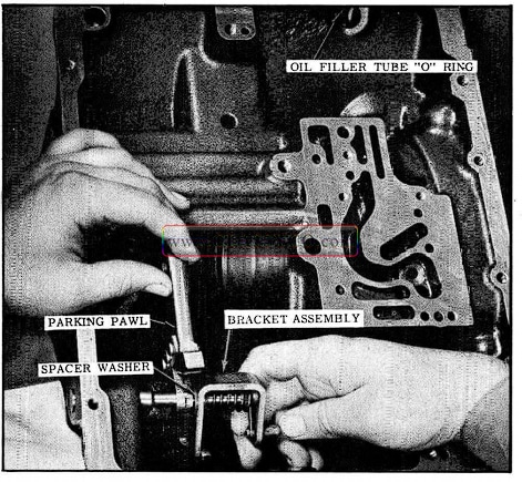
In order to remove the parking pawl bolt, the rear oil pump must be positioned rearward and rotated for clearance.
Exercise care to prevent damaging the rear oil pump gasket as it must be reused.
REMOVING THE HYDRA-MATIC TRANSMISSION
The Hydra-Matic transmission, torus cover and flywheel are removed from the car as an assembly.
- Disconnect battery.
- Disconnect transmission oil filler tube at engine.
- Raise car (on twin-post hoist).
- Remove oil pan drain plug and drain transmission. Reinstall plug.
- Disconnect speedometer cable at transmission.
- Disconnect manual and throttle linkage from transmission lever. REMOVE THROTTLE LEVER.
- Remove crankcase breather outlet tube.
- Scribe a line from one of the propeller shaft center bearing support to frame bolts on the frame member (for later center bearing support alignment).
- Remove the propeller shaft center bearing sup port bolts and shims. Identify shims so the same total thickness of shims can be reinstalled.
- Disconnect the 2 “U” bolts at companion flange at the transmission.
- Raise the center bearing assembly so it will clear the frame member and slide the front propeller shaft and bearing assembly approximately 2″ to the rear on the slip joint. (The bearing mounting plate will rest on the frame and keep the propeller shaft from dropping down.)
- Remove starter.
- Remove lower flywheel housing.
- Support transmission with unit-lift and an adapter that will accommodate the Jetaway transmission.
- Raise engine enough to relieve weight from rear engine mounts. Remove engine mount to cross member attaching bolts.
- Remove cross bar to frame attaching bolts, then remove cross member.
- Remove torus oil plug and drain torus. Reinstall plug and torque 6 to 7 ft. lbs.
- Install engine support bar (Tool 30-13), with support screw pilots seated into lower flywheel housing front attaching screw holes.
NOTE: Locate support bar forward on frame so that it will not interfere when lowering transmission.
- Lower unit-lift until it is free of transmission oil pan.
- Lower engine (using support bar adjusting screws), NOT TO EXCEED 1-1/2 INCHES, to permit removal of the two upper bell housing to block bolts.
- Disconnect oil cooler hoses from lines. Cap lines immediately.
- Raise unit-lift until it supports transmission.
- Remove the 4 flex plate to flywheel attaching nuts and note position of flywheel dowels in relation to the flex plate.
- Remove remaining flywheel housing to block bolts.
- Move transmission rearward approximately 3/4″ to clear dowels. (Standard thread holes adjacent to dowels are provided for installing bolts to push flywheel housing off the dowels.)
- Lower transmission from car.
INSTALLING THE HYDRA-MATIC TRANSMISSION
To install, reverse the above procedure and include the following:
Lubricate crankshaft pilot bore and wick in pilot bore with Synthetic Oil Seal Lubricant (Part No. 567196).
To assemble flex plate to flywheel, align one dowel in flywheel with the small recess adjacent to the small ear in the flex plate, then cross tighten and torque flex plate to flywheel attaching nuts 17-22 ft. lbs. Torque oil pan drain.
NOTE: Due to the design of the Jetaway Transmission alignment factors of the bell housing are not critical so flywheel housing alignment is not necessary.
Use a 4 inch “C” clamp to hold the bearing against spider journals and obtain clearance of the bearing snap rings when installing front propeller shaft to companion flange on transmission. Torque “U” bolt nuts 18 to 22 ft. lbs.
After transmission is installed, add 1 quart of Hydra-Matic fluid. Set parking brake, start engine and allow oil to reach operating temperature then add enough fluid to bring level to the “Full” mark on the dipstick.
NOTE: Transmission capacity: 11-1/2 quarts approximately (for oil change, pan removed). 13 quarts approximately (after complete overhaul). Adjust throttle and manual control linkage. (See Linkage Adjustment)
GENERAL SERVICE PRECAUTIONS
To aid the mechanic when servicing the trans mission, it is recommended that upon disassembly of a unit, all parts should be cleaned and inspected as outlined under CLEANING AND INSPECTION, then the unit should be reassembled before disassembly of other units to avoid confusion and interchanging of parts.
- Before disassembly of the unit, thoroughly clean the exterior of the unit.
- Disassembly and reassembly of the unit and the sub-assemblies must be made on a clean work bench. As in repairing any hydraulically operated unit, cleanliness is of the utmost importance; therefore, the bench, tools, and parts must be kept clean at all times.
- Seal protecting tools must be used when assembling the units to prevent damage to the seals. The slightest flaw in the sealing sur face of the seal can cause an oil leak.
- The aluminum castings and the valve parts are very susceptible to nicks, burrs, etc., and care should be exercised while handling them.
- The internal snap rings should be expanded and the external snap rings compressed if they are to be reused. This will insure proper seating when installed. DO NOT REUSE TRUARC SNAP RINGS.
- Replace all “O” rings and oil seals when servicing unit.
- Sealing compound should not be used on seals with neoprene coated outside diameters with the exception of the flywheel housing oil seal. (Front Oil Seal)
- During assembly of each unit, all internal parts must be lubricated with Hydra-Matic oil.
- The rear unit steel clutch plates must be installed with the single offset notches (on lugs) positioned directly above each other.
- Gears that may be installed either way should be installed the same as they were removed. If gears are not installed the same, the tooth contact would change which could result in noisy gears.
PARTS, CLEANING AND INSPECTION
After complete disassembly of a unit, all metal parts should be washed in a clean solvent and dried with compressed air. All oil passages should be blown out and checked to make sure that they are not obstructed; the small passages, such as in the front. pump slide, should be checked with tag wire. All parts should be inspected to determine which parts are to be relaced.
The various inspections of parts as follows:
- Inspect linkage and pivot points for excessive wear.
- Bearing and thrust surfaces of all parts should be checked for excessive wear and scoring.
- Check for broken seal rings, damaged ring lands and damaged threads.
- Mating surfaces of castings and end plates should be checked for burrs and irregularities. If a good seal is not apparent, burrs and irregularities may be removed by lapping the surface with crocus cloth. The crocus cloth should be held on a flat surface, such as a piece of glass.
- Castings should be checked for cracks and sand holes.
- Gear teeth should be checked for chipping, scoring, and excessive wear.
- A wear pattern may be apparent on the drive and driven lugs; however, this is to be considered normal and the amount of clearance between the drive and driven lugs will not affect operation of the units.
- Valves should be free of burrs and the shoulders of the valves must be square. Any burrs or irregularities may be removed by honing. Valves should be free to slide in their respective bores.
- Inspect composition clutch plates for damaged surfaces and loose facings. If flakes of facing material can be removed with the thumbnail, the plates should be replaced; however, com position plate discoloration is not an indication of failure.
- Inspect steel clutch plates for scored surfaces and damaged lugs. The 6 equally spaced waves must be .008″ to .012″ and can be checked by placing the plates on a flat surface.
- Inspect springs for distortion or collapsed coils. Slight wear (bright spot) on the sides of the springs is permissable.
- When inspecting bushings, fit the mating part into the bushing and observe the amount of looseness. Bushing clearance is excessive if more than .008 of an inch exists when checked with a wire feeler gauge.
ALIGNMENT OF LOWER FLYWHEEL HOUSING
Lower flywheel housing alignment is rarely re quired; however, if a new longer housing is used, alignment should be checked.
Misalignment is evident as a “step” between the block and the lower housing resulting from the location of the housing too far forward or rear ward on the block. This condition can be corrected by elongating the dowel holes so as to allow lower housing to move to the rear or to the front as required.
NOTE: Do not remove dowel pins or enlarge dowel pin holes with an oversize drill, as correct sidewise location of lower housing must be maintained for proper engagement of starter pinion and ring gear.
TRANSMISSION DISASSEMBLY
FLYWHEEL, TORUS MEMBERS AND
FLYWHEEL HOUSING REMOVAL
- Remove the 8 flywheel attaching nuts and remove the flywheel.
- Remove the “O” ring from the flywheel and discard.
- Remove the Tru-arc ring and the driven torus from the Mainshaft. (See Fig. 3-20)
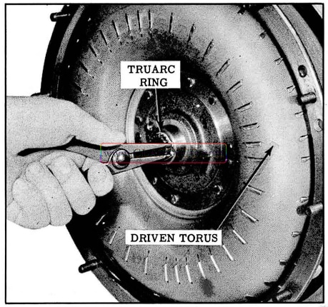
1957 Oldsmobile Removing Driven Torus
- Remove the driven torus rear Tru-arc ring from the mainshaft. (See Fig. 3-21)

1957 Oldsmobile Removing Snap Ring
- Remove the Tru-arc ring and drive torus from the intermediate shaft.
CAUTION: Do not attempt to remove drive torus and torus cover together.
- Remove the bronze and steel thrust washers from the intermediate shaft. (See Fig. 3-22)
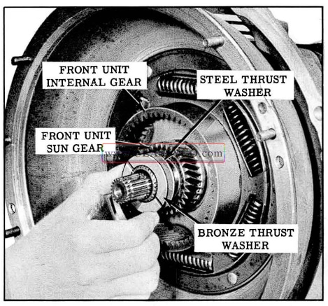
1957 Oldsmobile Removing Thrust Washers
- Remove the front unit sun gear and the steel washer.
NOTE: Sun gear can be installed with either side out, but to prevent possible gear noise, should be reinstalled the way it was removed.
- Slide the internal gear and the bronze thrust washer from the torus cover, then remove thrust washer from the internal gear.
- Remove the torus cover assembly.
- Remove the selective steel spacer from the hub of the front unit coupling driven torus. (See Fig. 3-23)
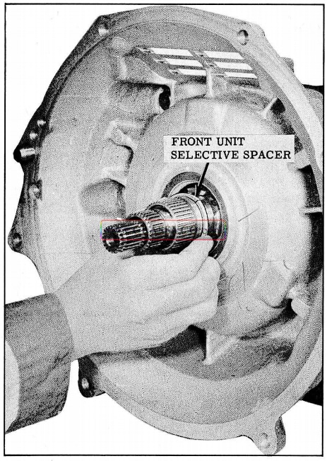
1957 Oldsmobile Removing Selective Spacer
NOTE: Spacer is now split at one end and may have remained in the internal gear.
- Install seal and bushing protector Tool J-6119 over the shafts. (See Fig. 3-24)
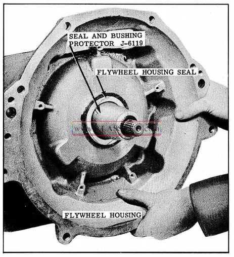
1957 Oldsmobile Seal and Bushing Tool
- Remove the 6 flywheel housing attaching bolts and washers, then remove the housing. Re move the tool from the housing.
- Remove the large “O” ring from the housing and discard.
FRONT UNIT COUPLING, MAIN OIL
CONTROL BODY AND FRONT PUMP REMOVAL
- Remove oil cooler adapter attaching bolts, copper washers, adapter, and gasket from the side of the transmission.
- Remove the 2 oil cooler sleeves and “O” rings from the side of the transmission with snap ring pliers.
- Slide the front unit coupling from the transmission. (See Fig. 3-25)

1957 Oldsmobile Front Unit Coupling Removal
- Bolt holding fixture 1-6115 to front of transmission with 4 flywheel housing bolts. (See Fig. 3-26)
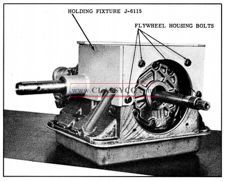
1957 Oldsmobile Transmission Holding Fixture
- Place in mounting fixture on the bench with oil pan up.
- Remove the oil pan bolts, then remove the oil pan and gasket.
- To avoid damage to screen, carefully pull rear pump intake pipe (small) from rear pump, then remove screen and pipe as an assembly.
- Remove the rear pump intake pipe “O” ring from the case.
- Remove the front pump intake pipe clamp, then pull the pipe from the front pump and remove the “O” ring from the pump.
- Remove the accumulator and servo assembly, which is under spring tension, by removing the 3 attaching bolts. (See Fig. 3-27) Remove the release spring.
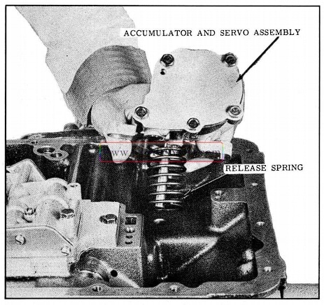
1957 Oldsmobile Accumulator and Servo Removal
- Remove the 5 remaining oil control valve body attaching bolts, then remove the oil control valve assembly. (See Fig. 3-28)
- Remove the front pump locating bolt from recess in the case. (See Fig. 3-28)
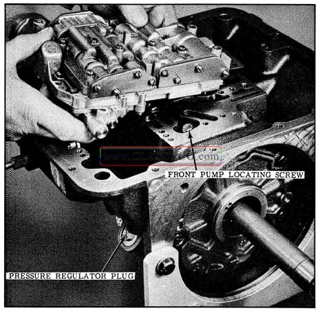
1957 Oldsmobile Oil Control Valve Body Removal
- Remove the pressure regulator plug assembly. (See Fig. 3-29)
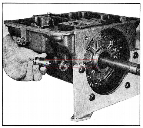
1957 Oldsmobile Pressure Regulator Plug Removal
- Remove the pressure regulator spring and valve. (See Fig. 3-30)
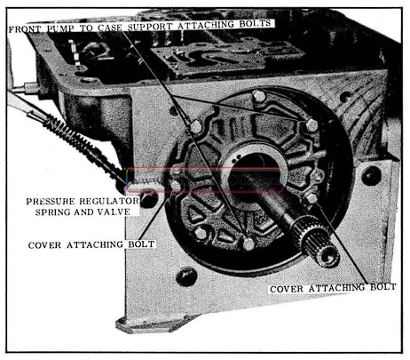
1957 Oldsmobile Spring and Valve Removal
- To remove the front pump, remove the 2 cover attaching bolts adjacent to the dowels and in stall slide hammer Tools J -6125 if necessary, then remove the 3 large front pump attaching bolts. (See Figs. 3-30 and 3-31)
- Pull pump from the case then remove tools from the pump.

1957 Oldsmobile Removing Front Pump
NOTE: Remove front sprag inner race if it remained on the intermediate shaft. (See Fig. 3-32)
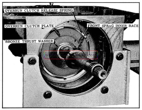
1957 Oldsmobile Removing Front Spring and Over run Clutch
- Remove overrun clutch release spring and the overrun clutch plate from the case support. Spring may have remained in the front pump.
- Remove bronze thrust washer from the intermediate shaft.
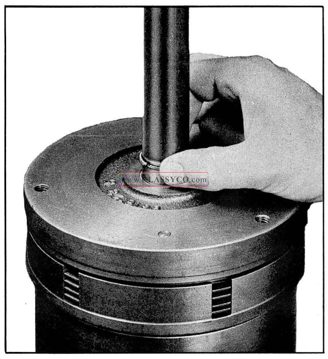
- Install Tool J-6135 over the intermediate shaft and against the case support, then tighten the locking bolt. (See Fig. 3-33)
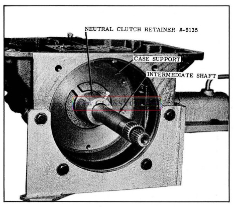
1957 Oldsmobile Neutral Clutch Retainer Tool
CHECK MAINSHAFT END PLAY
- Remove collar from Tool J-6127 and install on mainshaft. (See Fig. 3-34)
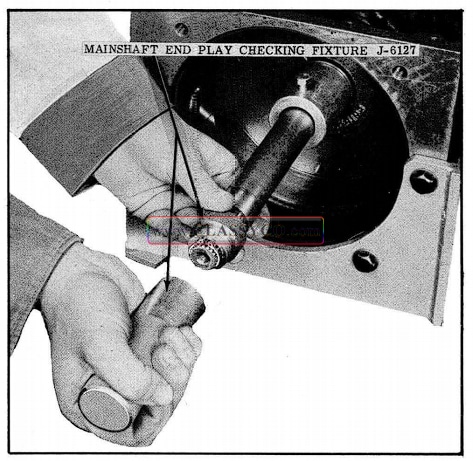
1957 Oldsmobile Mainshaft End Play Checking Tool
- Install Tru-arc ring on mainshaft, then install body of Tool J-6127 and tighten.
- Install Tool J-6126 on front of transmission and install dial indicator. (See Fig. 3-35)
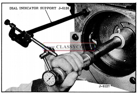
1957 Oldsmobile Checking Mainshaft End Play
- Move mainshaft in and out, end play should be .004″ to.018 “. Be sure to get free mainshaft end play, forcing main shaft will give inaccurate reading.
- Record amount of end play so proper selective washer can be installed when transmission is reassembled.
Nine mainshaft selective washers are avail able and are marked 1 through 9 according to last numeral of Part Number.
8617821
8617822
8617823
8617824
8617825
8617826
8617827
8617828
8617829
The selective washer is located on the output shaft between the reverse drive flange and the rear planet carrier.
- Remove tools from the transmission.
REAR OIL PUMP AND REVERSE UNIT REMOVAL
- Remove Companion Flange from output shaft using Puller 6295-01 and Puller Screw 6504. (See Fig. 3-36)
- Remove the rear oil seal with a blunt chisel.
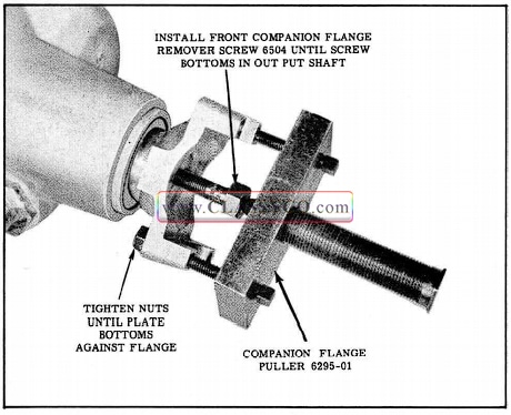
1957 Oldsmobile lnstalling Companion Flange Remover
NOTE: If speedometer driven gear is to be replaced, remove at this time.
- Remove the 8 rear extension housing attaching bolts, then remove the housing and gasket.
- Turn output shaft so that governor weight (G-1) is ·down, then pull the governor from the rear oil pump.
- Pull speedometer drive gear from the output shaft with Tool J-6123 and short bolts 6123-6. (See Fig. 3-37)
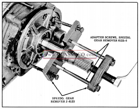
1957 Oldsmobile Removing Speedometer Drive Gear
- Remove the rear bearing snap ring from the output shaft with snap ring pliers. Remove breather pipe clamp screw and pry pipe from rear pump.
- Turn transmission to a vertical position with output shaft up and remove 2 opposite rear pump cover attaching bolts. (See Fig. 3-38) Install Tool J-6123 with shorter bolts 6123-6, then remove rear pump locating screw and the 1 pump to case attaching bolt.
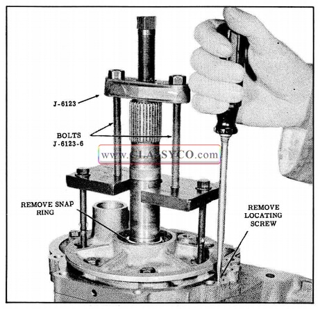
1957 Oldsmobile Removing Rear Pump
- Tighten tool bolts to pull rear oil pump and rear bearing from the output shaft.
- Remove the tool from the rear pump.
- Remove the oil pump to case gasket.
- Lift the reverse internal gear and bronze thrust washer from the output shaft. (See Fig. 3-39), then remove thrust washer from internal gear.
- Remove the reverse clutch release spring. (See Fig. 3-39)
- Remove the reverse piston release spring. (See Fig. 3-39)
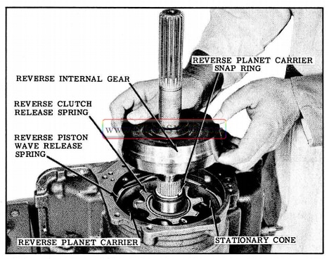
1957 Oldsmobile Removing Reverse Internal Gear
- Remove the reverse planet carrier snap ring from the output shaft.
- Lift the reverse planet carrier and stationary cone from the case.
- Remove the stationary cone lock from the case. (See Fig. 3-40)
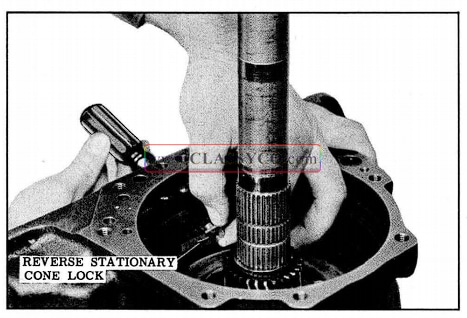
1957 Oldsmobile Removing Reverse Stationary Case Lock
CASE SUPPORT, NEUTRAL CLUTCH, AND REAR UNIT REMOVAL
- Turn transmission to a horizontal position and remove the case support snap ring from the front of the case. (See Fig. 3-41)
- Remove the case support lock bolt from the side of the transmission. (See Fig. 3-41)
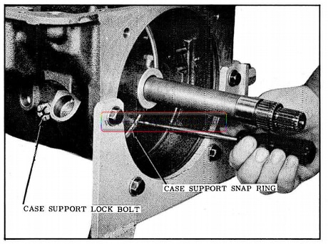
1957 Oldsmobile Removing Case Support Snap Ring
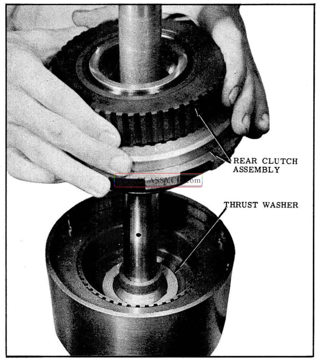
- Remove the case support, neutral clutch and rear unit as an assembly by sliding toward front of case while rocking the assembly to prevent the case support from binding. (See Fig. 3-42)
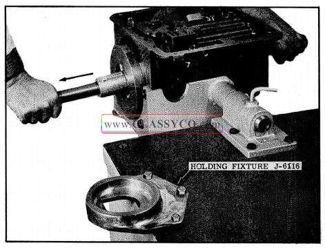
1957 Oldsmobile Removing Case Support, Neutral Clutch and Rear Unit
- Place assembly in holding fixture J-6116, output shaft down. (See Fig. 3-43)
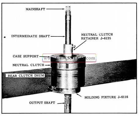
1957 Oldsmobile Assembly in Holding Fixture
NOTE: If the assembly is a tight fit in the case, install slide hammers J -6125 and adapters J-6134-1 into the case support and use to free case support from the case. (See Fig. 3-44)
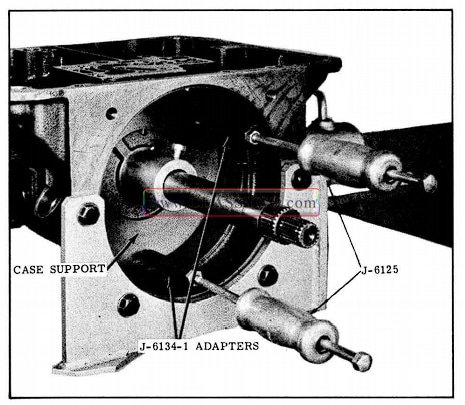
1957 Oldsmobile Case Support Removal
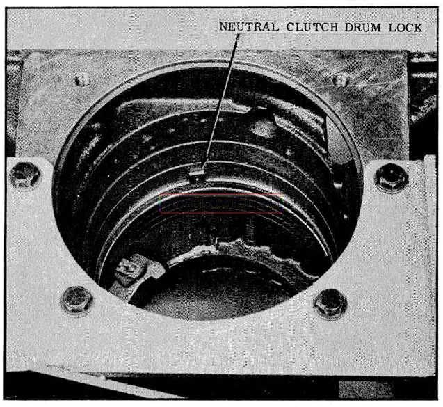
- Remove the neutral clutch drum lock from the case. (See Fig. 3-45)
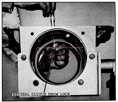
1957 Oldsmobile Removing Lock from Case
- Remove low band from case by disengaging from case anchor, rotate band to a horizontal position and turn it so that the ends are facing rear of case, then pull band from front of case.
THROTTLE AND MANUAL LEVER SHAFTS AND PARKING PAWL REMOVAL
- Remove the retaining ring from the manual lever shaft. (See Fig. 3-46)
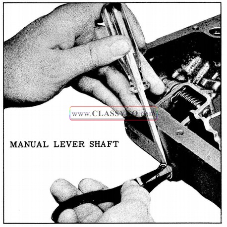
1957 Oldsmobile Removing Retaining Ring
- Push the shaft assembly part way into the case, then back into position and remove the flat washer and “O” ring. (See Fig. 3-47) Remove the shaft assembly and spacer washer from the case.
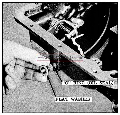
1957 Oldsmobile Removing Flat Washer and O Ring
- Install a rear extension housing bolt into the parking pawl pivot shaft, then slide the pivot shaft from the case while turning the shaft. (See Fig. 3-48) Remove the bolt from pivot shaft.
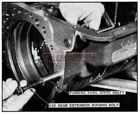
1957 Oldsmobile Removing Pivot Shaft
- Lift the parking pawl and remove spacer from recess in pivot shaft boss in the case.
- Remove retaining clip from link shaft.
- Rotate the pawl upward and slide the pawl and bracket lever assembly from the shaft being careful not to drop the spacer washer. (See Fig. 3-49)
1957 Oldsmobile Pawl and Bracket Removal
- Clean and inspect the transmission case. (See Figs. 3-50 and 3-51)
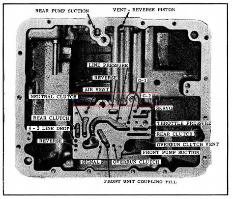
1957 Oldsmobile Oil Passages (Bottom of Case)
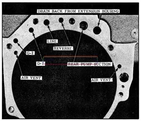
1957 Oldsmobile Oil Passages (Rear of Case)
DISASSEMBLY AND ASSEMBLY OF INDIVIDUAL UNITS
DISASSEMBLY OF THROTTLE AND MANUAL LEVERS (FIG. 3-52)
- Remove spacer washer from manual lever shaft.
- Pull the pin from the throttle lever shaft and remove the shim or shims.
NOTE: Shims are used to keep end play to a minim um.
- Remove throttle lever shaft from manual lever shaft.
- Remove the “O” ring from manual lever shaft.
- Clean and inspect parts.
ASSEMBLY OF THROTTLE AND MANUAL LEVERS
- Install throttle shaft into manual lever shaft.
- In stall “O” ring into counter bore in manual lever shaft, use Hydra-Matic oil on “O” ring.
- Install sufficient number of shims to remove end play, then install retaining pin.
- Install spacer washer on manual lever shaft.
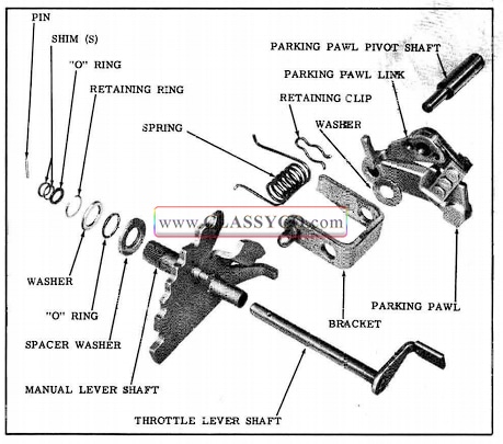
1957 Oldsmobile Manual and Throttle Lever Shafts
PARKING PAWL, THROTTLE AND MANUAL LEVER INSTALLATION
- Install parking pawl pivot shaft spacer in recess in the case. (See Fig. 3-53)
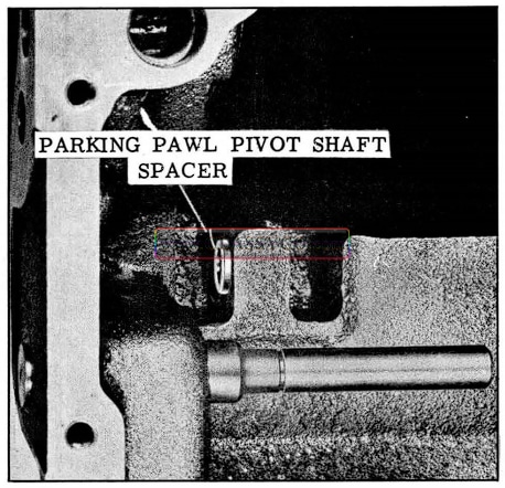
1957 Oldsmobile Installing Pivot Shaft Spacer
- Slide parking pawl link over shaft and position parking pawl between bosses in the case.
- Align holes in parking pawl with holes in the case and install parking pawl pivot shaft from rear of the case.
- Place spacer washer on the link shaft.
- Install bracket and spring on the shaft. (See Fig. 3-54)
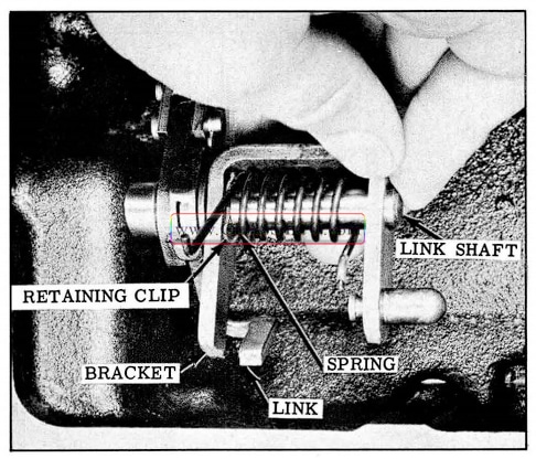
1957 Oldsmobile Installing Bracket and Spring
- Turn bracket to contact top side of the link.
- With short end of spring against bracket pin, hook long end under the link.
- Install retaining clip in groove on link shaft.
- Install throttle and manual lever shaft assembly into the case, then rotate so that pin engages with manual lever.
- Install “O” ring on manual lever shaft and seat it into the recess in the case. Use HydraMatic oil on “O” ring.
- Install flat washer and retaining ring on manual lever shaft.
DISASSEMBLY OF THE CASE SUIPPORT, NEUTRAL CLUTCH AND REAR UNIT
- Remove Tool J -6135 from the intermediate shaft.
- Unhook the lock type oil ring, then remove the ring from the intermediate shaft. (See Fig. 3-55)
1957 Oldsmobile Lock Type Oil Ring Removal
- Lift the case support with neutral clutch piston from the intermediate shaft. (See Fig. 3-56)
1957 Oldsmobile Removing Case Support
- Remove the 2 oil rings from the case support hub.
- Remove neutral clutch piston from case support by bumping the hub on a wood block. (See fig. 3-57)
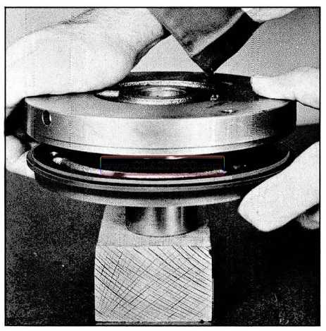
1957 Oldsmobile Neutral Clutch Piston Removal
- Inspect oil seals and oil rings on the case support hub and neutral clutch piston. Remove parts if replacement is necessary.
- Lift the neutral clutch drum assembly from the intermediate shaft. (See Fig. 3-58)
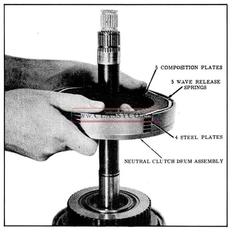
1957 Oldsmobile Neutral Clutch Drum Removal
- Remove the clutch plates and wave release springs from the neutral clutch drum. (5 composition, 4 steel and 5 wave release springs)
- Remove the large snap ring from the rear drum. (See Fig. 3-59)
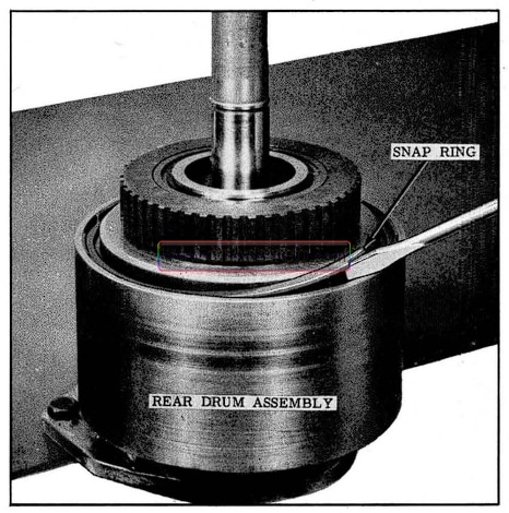
1957 Oldsmobile Snap Ring Removal
- Lift the intermediate shaft and rear clutch assembly from the drum. (See Fig. 3-60)
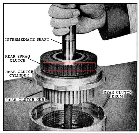
1957 Oldsmobile Intermediate Shaft and Rear Clutch Removal
- Lift the rear sprag and clutch assembly from the intermediate shaft. (See Fig. 3-61)
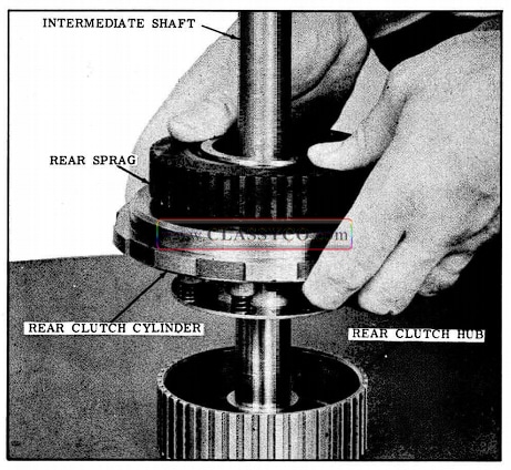
1957 Oldsmobile Rear Spring and Clutch Removal
- Remove thrust washers from both sides of the clutch hub.
NOTE: One thrust washer may remain on the mainshaft sun gear.
- Remove the Spirolox ring from the rear sprag inner race. (See Fig. 3-62)
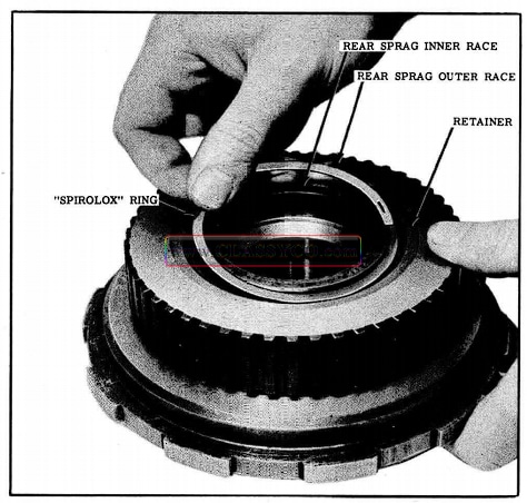
1957 Oldsmobile Spirolox Ring Removal
- Remove sprag outer race and retainer by rotating outer race counter-clockwise and pulling upward.
- Slide the sprag assembly and retainer from the outer race.
NOTE: Do not disassemble the sprag.
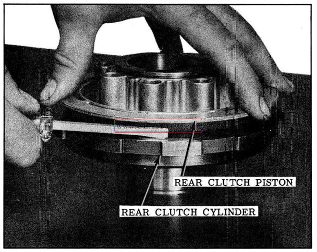
- Place rear clutch cylinder assembly over Tool J-6129 and install modified Tool J-4670-B. (See Fig. 3-63)
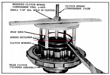
1957 Oldsmobile Snap Ring Removal (2)
- Tighten tool nut to compress clutch release springs, then disengage the snap ring.
- Remove the tools from the rear clutch and remove the snap ring and spring retainer.
- Remove the eight clutch release springs.
- Remove the clutch piston from the rear clutch cylinder. (See Fig. 3-64)
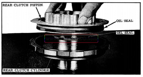
1957 Oldsmobile Clutch Piston Removal
- Remove the oil seal from the piston and cylinder.
- Remove main shaft assembly and thrust washer from the rear unit.
NOTE: Thrust washer may remain in counter bore in output shaft.
- Remove the 7 composition plates and 7 steel plates from the rear unit.
- Invert the output shaft and drum assembly on the bench.
- Remove the reverse drive flange snap ring from the rear drum.
- Lift the output shaft and reverse drive flange from the drum.
- Remove reverse drive flange snap ring from the output shaft, then lift the flange from output shaft.
- Remove the selective thrust washer from the reverse drive flange.
NOTE: Thrust washer may remain on the output shaft.
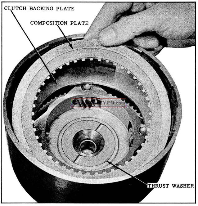
- Slide the internal gear and the rear clutch backing plate from the rear drum. (See Fig. 3-65)
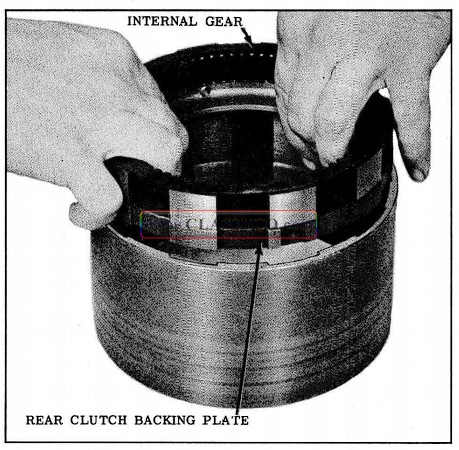
1957 Oldsmobile Internal Gear Clutch Backing Plate Removal
- Clean and inspect all parts.
NOTE: Internal gear must be reinstalled with chamfered side toward backing plate to prevent possible gear noise.
CHECK MAINSHAFT SUN GEAR END PLAY
Measure end play of rear unit sun gear on main shaft to determine correct selective washer to be used in the rear unit.
- Clamp sun gear and mainshaft assembly in holding fixture J -6116 using “C” clamp and dial indicator KMO 30. (See Fig. 3-66) Be sure gear is firmly clamped on both sides so it cannot move.
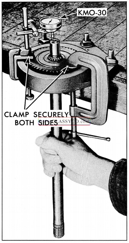
1957 Oldsmobile Check Mainshaft Sun Gear End Play
- Set dial indicator to contact end of mainshaft.
- Move mainshaft STRAIGHT up and down to measure end play and record.
- Subtract this end play from the mainshaft end play recorded before the transmission was disassembled. The difference will be the actual end play of the rear unit and should be .004 to .018.
EXAMPLE: Mainshaft End Play .023″
Rear Unit Sun Gear End Play – .012″
Rear Unit End Play .011″
ASSEMBLY OF THE REAR UNIT (FIG. 3-68)
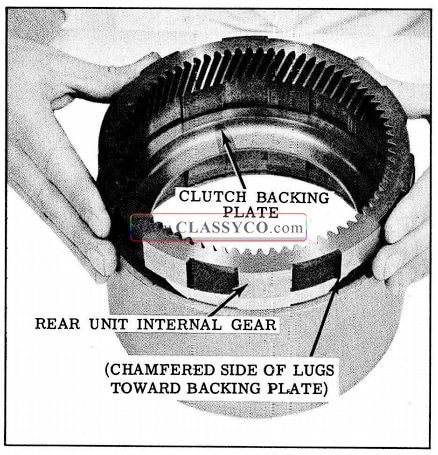
- Install the clutch backing plate against the shoulder in the rear drum.
- Place the rear unit internal gear on the backing plate. (See Fig. 3-67)
1957 Oldsmobile Rear Unit Internal Gear Installation
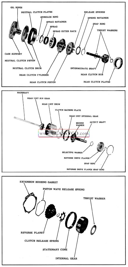
1957 Oldsmobile Rear Unit Assemblies
NOTE: Make sure gear is installed with chamfered side of lugs toward clutch backing plate to prevent possible gear noise.
- Position selective washer in recess of the reverse drive flange. (Retain with petrolatum)
- Install output shaft into the reverse drive flange, (See Fig. 3-69) then invert the assembly on the bench while holding the flange against the planet carrier to prevent the washer from dropping out of place.
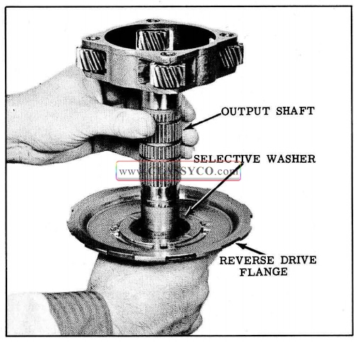
1957 Oldsmobile Installing Reverse Drive Flange
- Install snap ring on output shaft adjacent to the reverse sun gear.
- Install reverse drive flange retainer J-6120 on output shaft between sun gear and snap ring. (See Fig. 3-70)
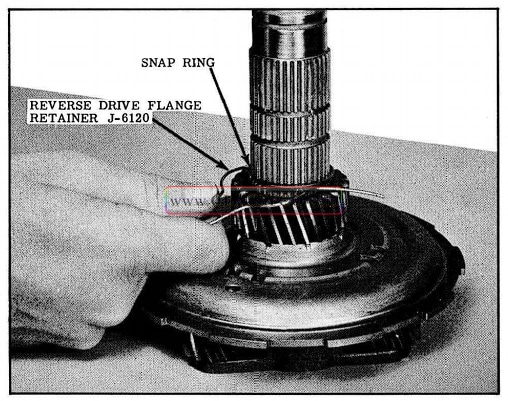
1957 Oldsmobile Installing Retainer Tool
NOTE: This is to prevent the selective thrust washer from dropping out of place when installing output shaft into rear unit drum.
- Install output shaft assembly into rear unit drum, then install snap ring into the drum. (See Fig. 3-71)
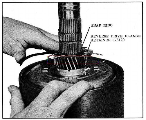
1957 Oldsmobile Installing Snap Ring
- Place the assembly, with output shaft down, part way into holding fixture J-6116, then hold the rear drum and remove reverse drive flange retaining tool as shown in Fig. 3-72. Lower the drum until reverse drive flange rests on holding fixture.
1957 Oldsmobile Removing Retainer Tool
- Install thrust washer in counter bore of output shaft.
- Lubricate composition plates with Hydra-Matic oil as they are installed. Place a composition plate on the backing plate and install a steel plate. Alternate until 7 composition plates and 7 steel plates have been installed. (See Fig. 3-73)
1957 Oldsmobile Installing Clutch Plates
NOTE: The steel clutch plates must be in stalled with the single offset notches (on lugs) positioned directly above each other.
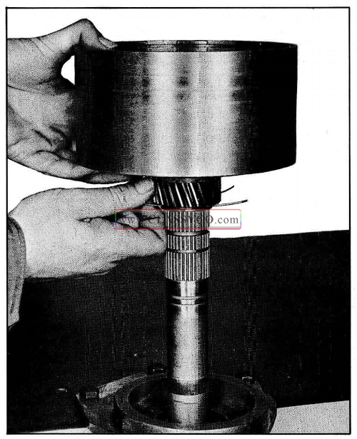
- Install mainshaft by engaging the sun gear with the rear planet pinions.
NOTE: If the mainshaft and sun gear were disassembled for any reason, the side of the sun gear with the drill point should be toward rear of mainshaft.
- Install thrust washer in rear clutch hub on side opposite the intermediate shaft and retain with petrolatum. (See Fig. 3-74)
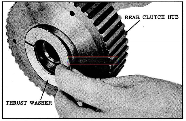
1957 Oldsmobile Installing Thrust Washer
- Install intermediate shaft and clutch hub assembly into the rear unit so that top of clutch hub is flush with steel plate. (See Fig. 3-75)
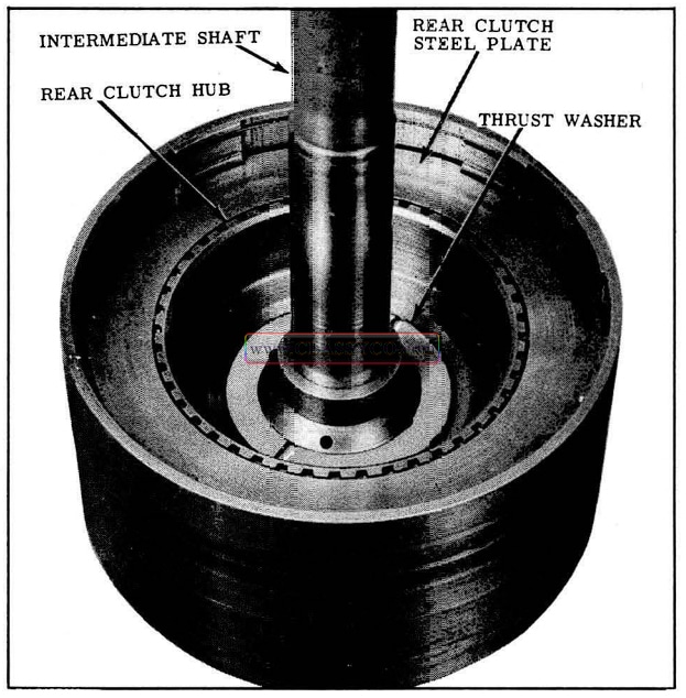
1957 Oldsmobile lnstalling Intermediate Shaft
- Install the thrust washer over intermediate shaft and onto the clutch hub.
- Install new oil seals on the rear clutch piston and cylinder. (See Fig. 3-76), Lubricate seals with Hydra-Matic oil.
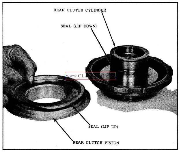
1957 Oldsmobile Installing Oil Seal
- Place the clutch piston on the clutch cylinder so that it rests on the Hp of the seal. While applying light pressure on the piston, work the seal lip into the clutch cylinder. (See Fig. 3-77)
1957 Oldsmobile Installing Rear Clutch Piston
- Install the 8 clutch release springs into the piston.
- Place the rear clutch assembly over Tool J -6129 and place the spring retainer on the release springs with the tangs facing up.
- Lay snap ring on the retainer and install modified Tool J-4670-B.
- Compress the springs with the tool and install snap ring.
- Remove the tools from the rear clutch assembly and check to see that the snap ring is not on any of the tangs.
- With the recessed side of the rear sprag outer race facing up and with the shoulder of the sprag up, install it into the outer race by turning the sprag counter-clockwise. (See Fig. 3-78)
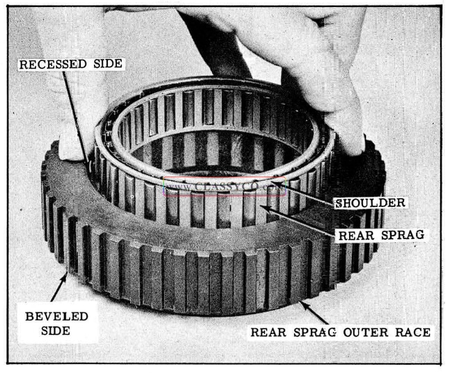
1957 Oldsmobile Installing Rear Spring
- Install sprag assembly on clutch cylinder with the beveled side of outer race toward the hub by turning sprag counterclockwise. (See Fig. 3-79)
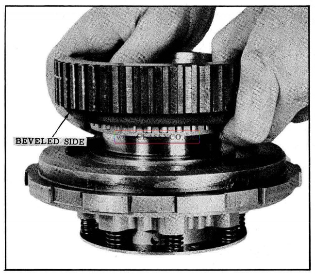
1957 Oldsmobile Installing Sprag Assembly
- Place sprag retainer on sprag and outer race, then install Spirolox ring. (See Fig. 3-80)
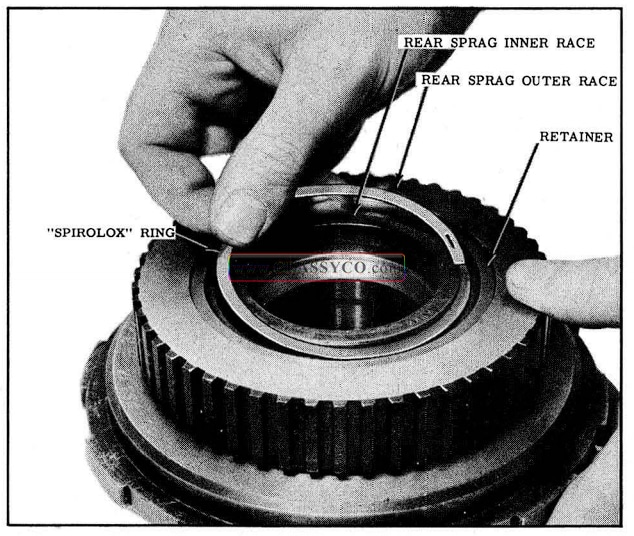
1957 Oldsmobile Installing Spirolox Ring
- Install rear clutch assembly into rear unit drum, then install the large snap ring. (See Fig. 3-81)
1957 Oldsmobile Installing Rear Clutch Assembly
NOTE: It may be necessary to lift up on the drum to allow snap ring to enter the groove.
- Place the neutral clutch drum on rear unit with clutch plate surface up. (See Fig. 3-82)
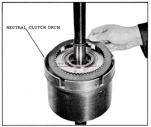
1957 Oldsmobile Installing Neutral Clutch Assembly
- Lubricate composition plates with Hydra-Marie oil. Install a wave release spring in the clutch drum, then place a composition plate over sprag outer race and install a steel plate. Alternate until 5 composition plates, 4 steel plates and 5 wave release springs have been installed.
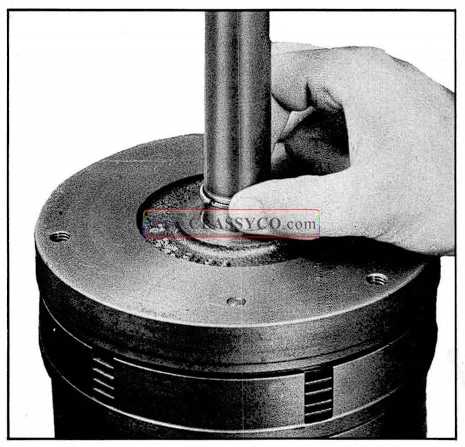
- Place the inner (small) seal over the case support hub with the sealing lip down, working the seal into the groove on the case support hub. (See Fig. 3-83) Lubricate the seal with Hydra-Matic oil.
- Install the neutral clutch piston in the case support with the dowel pins aligned with the holes, working the piston down over the inner seal. (This will insure that the inner seal is properly installed.)
- Remove neutral clutch piston and install outer seal (large) with sealing lip up. (See Fig. 3-83). Lubricate seal with Hydra-Matic oil.
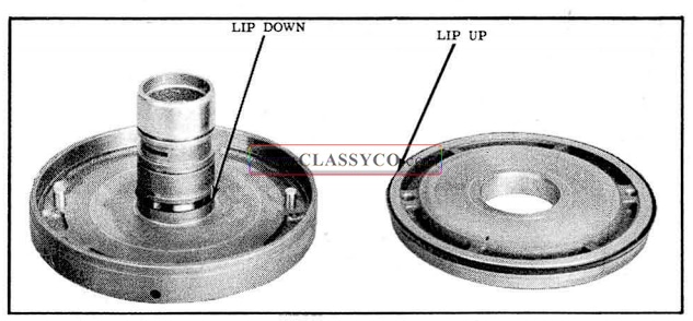
1957 Oldsmobile Installing Neutral Clutch Piston Oil Seals
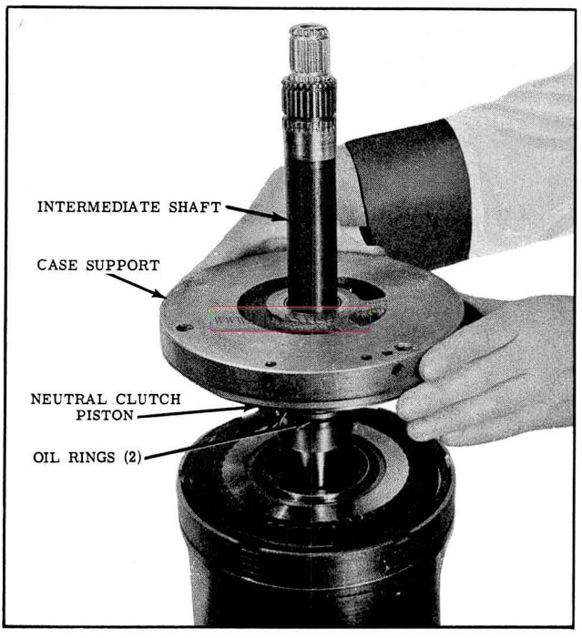
- Install neutral clutch piston in the case support with the dowel pins aligned, compressing seal with a blunt screw driver to allow piston to enter the drum. (Use care so seal is not damaged as piston enters case support.)
- Install the 2 oil rings on hub of the case support; lubricate the rings with Hydra-Matic oil.
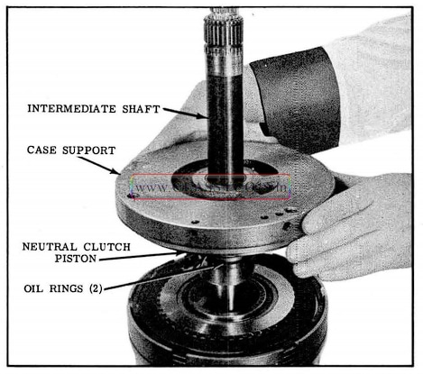
- Install case support assembly, hub down, over the intermediate shaft, being careful not to damage the bushing while passing over the sharp shoulders on the shaft. (See Fig. 3-84)
1957 Oldsmobile Installing Case Support
- Install lock type oil ring on the intermediate shaft. (See Fig. 3-85)
1957 Oldsmobile Installing Lock Type Oil Ring
- Install Tool J -6135 over the intermediate shaft and push down on case support to compress clutch release springs, then tighten lock bolt. (See Fig. 3-86)
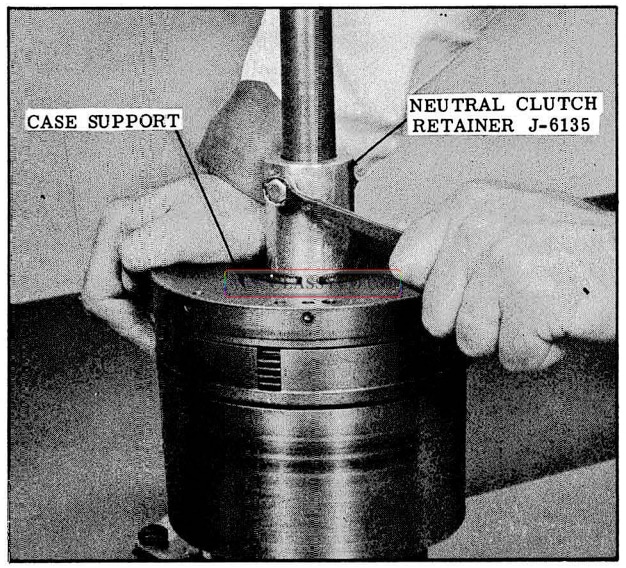
1957 Oldsmobile Installing Neutral Clutch Retainer
INSTALLATION OF THE REAR UNIT INTO THE CASE
LOW BAND
- Slide band into front of the case with band ends to rear of the case. (See Fig. 3-87)
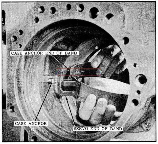
1957 Oldsmobile Installing Low Band
- When the band is half way in the case, rotate it so that the end of the band will hook onto the case anchor.
- Hook band end on case anchor.
CASE SUPPORT, NEUTRAL CLUTCH AND REAR UNIT
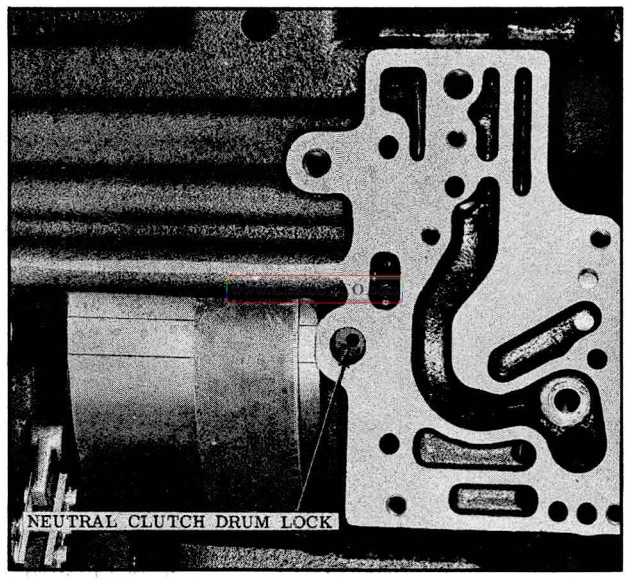
- Install neutral clutch drum 1ock into the case and retain with petrolatum. (See Fig. 3-88)
1957 Oldsmobile Lock Installation
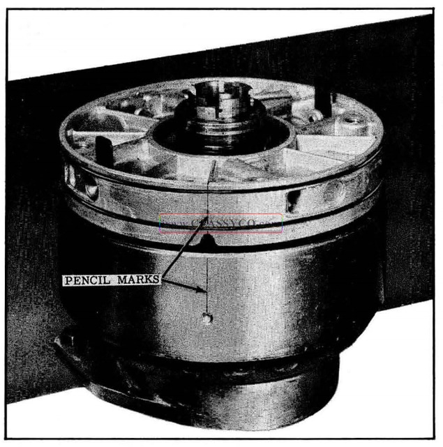
- Hold neutral clutch drum and turn case support to align case support lock bolt hole with center of clutch plate drive lugs as shown in Fig. 3-89. Mark rear drum with a pencil as shown.
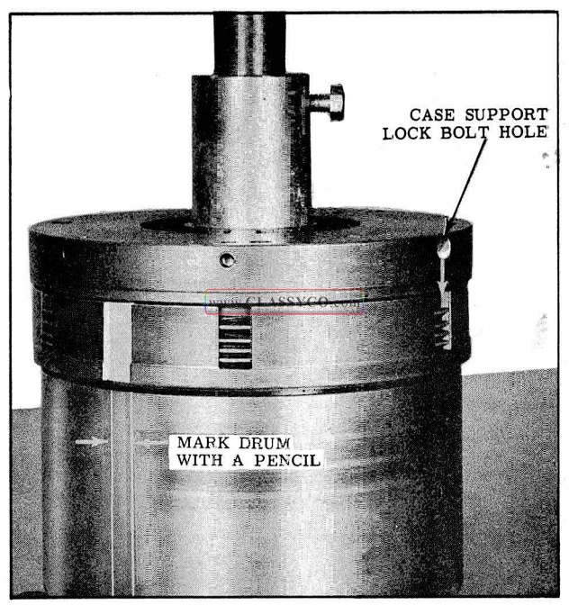
1957 Oldsmobile Correct Alignment
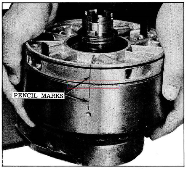
- Install case support, neutral clutch and rear unit assembly into transmission with pencil marks on rear drum aligned with neutral clutch drum lock. (See Fig. 3-90)
1957 Oldsmobile Installing Neutral Clutch, Case Support and Rear Unit
CAUTION: Do not knock low band off case anchor when installing assembly. Check position of band end before assembly is pushed into place.
- Make sure hole in the case support and hole in the case are aligned, then install case support snap ring into the case.
NOTE: It may be necessary to install slide hammers, Tool J-6125 with adapters J-6134-l, in the case support to seat the support so that the snap ring will enter the groove.
- Install the case support lock bolt and torque 25 to 30 ft. lbs.
DISASSEMBLY OF THE FRONT UNIT COUPLING
- Scribe a mark on the front unit coupling and cover, then remove snap ring.
- Install Tools J-6122 -1 to retain the two exhaust valves, then install Tool J -6121 to front unit coupling. (See Fig. 3-91)
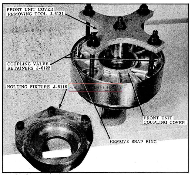
1957 Oldsmobile Cover Removing Tools
- Place the assembly in holding fixture J-6116, then tighten the center nut. Make sure the 4 studs are tight in the cover.
- Tighten the 4 nuts alternately to prevent cocking the cover while removing. (See Fig. 3-92) There are 2 square “O” rings that will hang up in the snap ring groove and a greater effort will be required to shear the rings when the y drop into the snap ring groove.
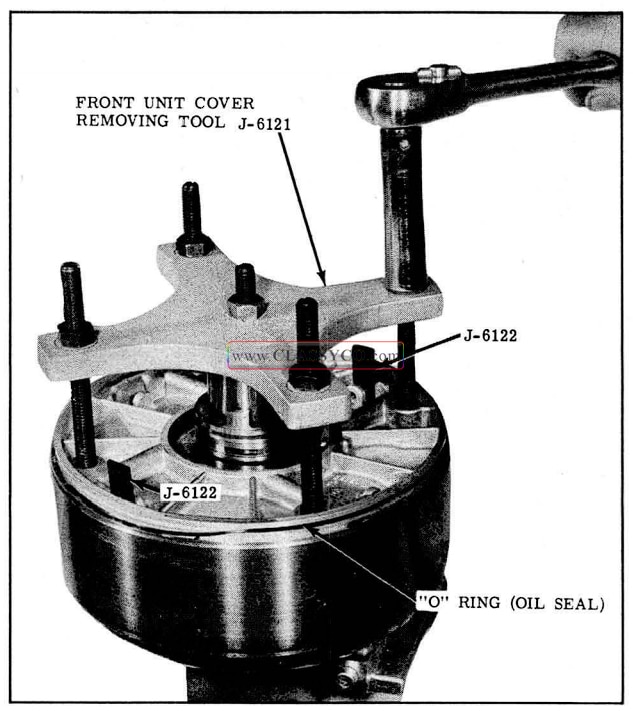
1957 Oldsmobile Removing Front Unit Coupling Cover
- When the cover is free of the coupling remove the exhaust valve retaining tools, exhaust valves and springs.
- Remove the tools from the front unit coupling.
- Lift the cover and the driven torus from the coupling.
- Remove spacer and bronze thrust washer from driven torus shaft.
- Clean and inspect all parts.
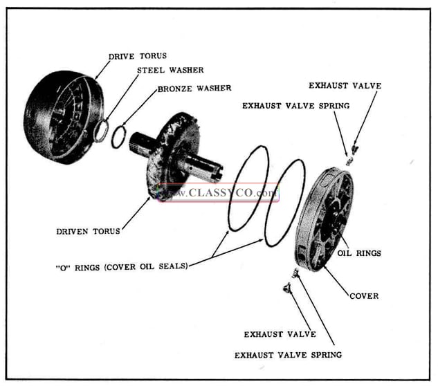
ASSEMBLY OF THE FRONT UNIT COUPLING (Fig. 3-93)
- Place drive torus in holding fixture and install the steel spacer in counter bore on vane side of drive torus, then install bronze thrust washer.
- Install driven torus into the drive torus.
- Install New “O” rings on the front unit coupling cover, making sure the “O” rings are not twisted in the groove.
- Lubricate the “O” rings and the snap ring groove in drive torus with petrolatum.
- Install springs and exhaust valves in cover and retain with Tool]-6122.
1957 Oldsmobile Front Unit Coupling
- Place cover on drive torus with marks aligned. Mark cover and drive torus with a pencil to indicate the notch and locating pin. (See Fig. 3-94)
1957 Oldsmobile Coupling Cover Alignment
- With the cover resting on the bottom “O” ring push the cover as far as possible into the coupling. (See Fig. 3-95)
1957 Oldsmobile Installing Coupling Cover
- Make sure pencil marks are still aligned, then tap cover into place with a composition hammer until snap ring can be installed.
NOTE: Tap on alternate sides of cover on puller bolt hole bosses to prevent binding the cover.
- Inspect snap ring groove. If part of “O” ring is visible, the cover will need to be removed and new “O” rings installed.
- Install snap ring.
DISASSEMBLY OF THE FRONT OIL PUMP
- Remove the 2 remaining bolts from the pump cover, then lift the cover from the pump body.
- Remove the top vane ring and the rotor. (See Fig. 3-96)
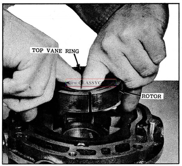
1957 Oldsmobile Rotor Removal
- Remove the 7 vanes and the lower vane ring.
- Remove the slide by pushing toward the priming springs, then lift out of the body from the opposite side. (See Fig. 3-97)
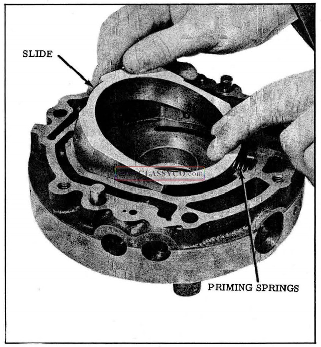
1957 Oldsmobile Removing Front Pump Slide
- Remove the inner and outer priming springs.
- Remove the torus feed valve retaining pin, cap, spring and valve. (See Fig. 3-98)
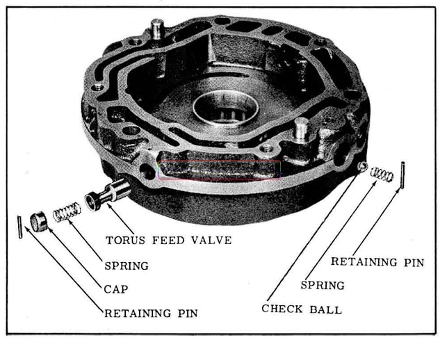
1957 Oldsmobile Front Oil Pump Valves
- Remove the check ball retaining pin and spring, then remove the check ball.
- Remove the front sprag inner race if it remained in the pump during disassembly, then remove the Spirolox retaining ring from the outer race. (See Fig. 3-99)
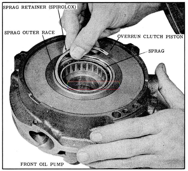
1957 Oldsmobile Removing Spirolox Ring
- Remove sprag assembly from the front pump. Do not remove outer race.
- Remove over run clutch piston from the pump by tapping on rear of pump with a composition hammer. (See Fig. 3 -100)
1957 Oldsmobile Removing Overrun Clutch Piston
ASSEMBLY OF THE FRONT OIL PUMP (Fig. 3-102)
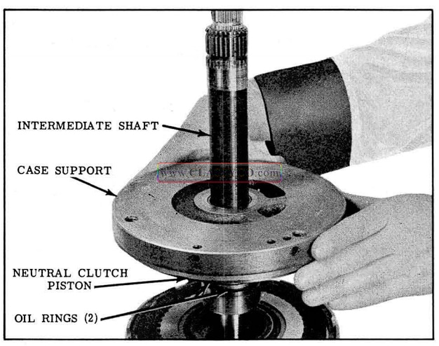
- Place the inner (Small) seal over the front oil pump hub with the sealing lip down (See Fig. 3-101) working the seal into the groove on the oil pump hub. (Lubricate seal with Hydra-Matic Oil)
- Install the overrun clutch piston in the oil pump with the dowel pins aligned with the holes, and work the piston down over the seal. (This will assure that the inner seal is properly installed)
- Remove the overrun clutch piston and install outer seal (large) on the piston with the sealing lip up. (See Fig. 3-101) Lubricate seal with Hydra-Matic oil.
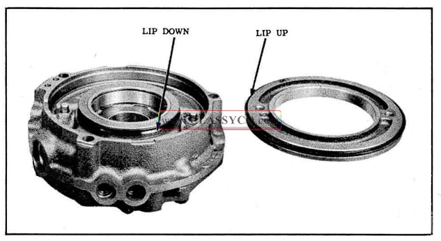
1957 Oldsmobile Installing Overrun Clutch Piston Oil Seals
- Install the overrun clutch piston in the front oil pump (with the dowel pins aligned with the holes) using a blunt screw driver to compress the outer seal.
CAUTION: There are three cast recesses on the outer edge of the pump. Be sure the outer seal passes each of these recesses with out being damaged.
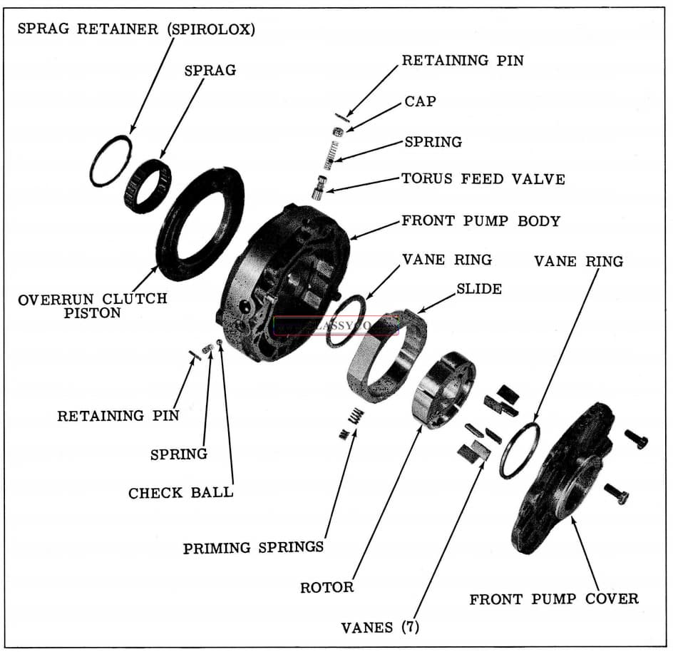
1957 Oldsmobile Front Oil Pump
- Install the sprag assembly, with shoulder up, into the sprag outer race. (See Fig. 3-103)
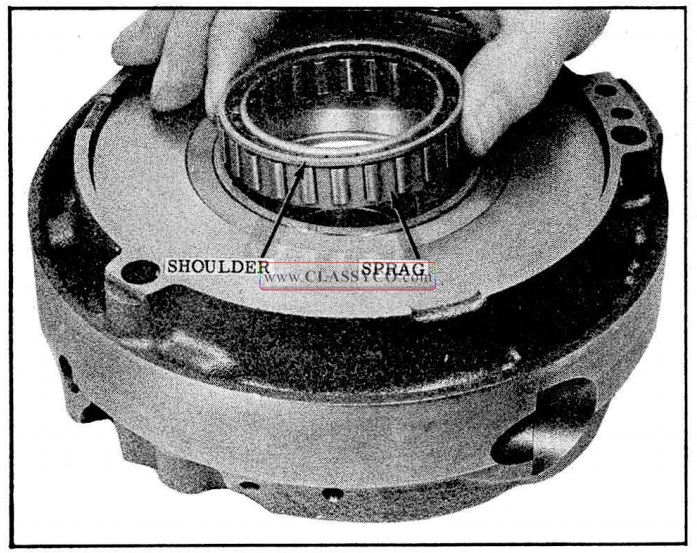
1957 Oldsmobile Installing Sprag Assembly (2)
- Install inner race of sprag with drive lugs up and check rotation. With sprag properly installed the inner race will be free to turn counter-clockwise and will lock up if turned clockwise.
- Install Spirolox ring in the outer race of the sprag.
- Install inner and outer priming springs in the recess of the pump body.
- Compress priming springs with the slide and allow slide to drop into the pump body. (See Fig. 3-104)
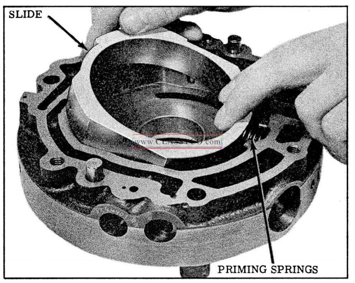
1957 Oldsmobile Installing Front Pump Slide
- Position vane ring in the pump cavity and locate in the center of the slide.
- Install the rotor into the pump with the drive slots facing up. (See Fig. 3-105)
- Install the 7 vanes in the rotor with the full wear pattern against the slide.
- Install the top vane ring.
- Install torus feed valve, spring, cap and retaining pin. (See Fig. 3-105)
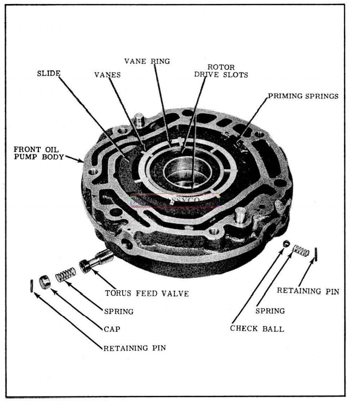
1957 Oldsmobile Front Oil Pump (2)
- Install ball check, spring and retaining pin.
- Place the cover on front pump body and install 2 cover bolts midway between the 2 dowels.
NOTE: SHORT COVER BOLT MUST BE INSTALLED ABOVE EXHAUST PASSAGE.
DISASSEMBLY OF THE PRESSURE REGULATOR (Fig. 3-106)
- Remove the reverse booster plug and the pressure regulator valve stop pin from the pressure regulator plug.
- Remove the “O” ring from the pressure regulator plug and discard.
- Clean and inspect parts.
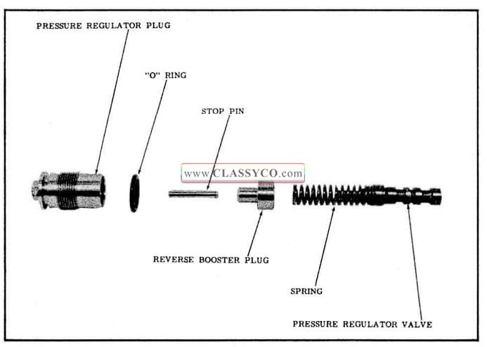
1957 Oldsmobile Pressure Regulator Assembly
ASSEMBLY OF THE PRESSURE REGULATOR VALVE
- Install a new “O” ring on the pressure regulator plug.
- Apply petrolatum on the reverse booster plug, then install it into the pressure regulator plug.
- Install stop pin in the booster plug and retain with petrolatum.
DISASSEMBLY OF THE REAR OIL PUMP
- Lift the reverse piston from the front of the pump assembly. (See Fig. 3-107)
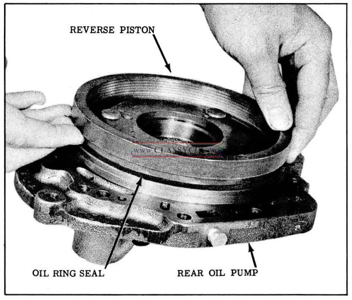
1957 Oldsmobile Reverse Piston Removal
- Remove the 6 rear pump cover attaching bolts, then separate the rear pump cover from the body by holding the cover and tapping on the body with a composition hammer.
- Remove 2 rear pump check valves and springs.
- Remove governor drive key from driven gear. (See Fig. 3-108)
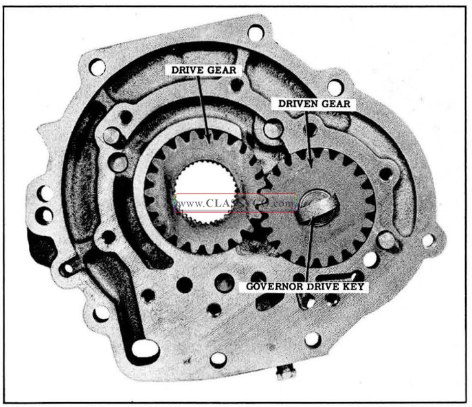
1957 Oldsmobile Rear Oil Pump Gears
- Remove drive and driven gears and note which side of gears is up for assembly purposes.
- Remove the pump gasket.
- Remove the snap ring from the cover, then remove the bearing.
- Clean and inspect parts.
ASSEMBLY OF THE REAR OIL PUMP (Fig. 3-109)
- Install drive and driven gears. Gears should be reinstalled with same side up.
- Install governor drive key into driven gear.
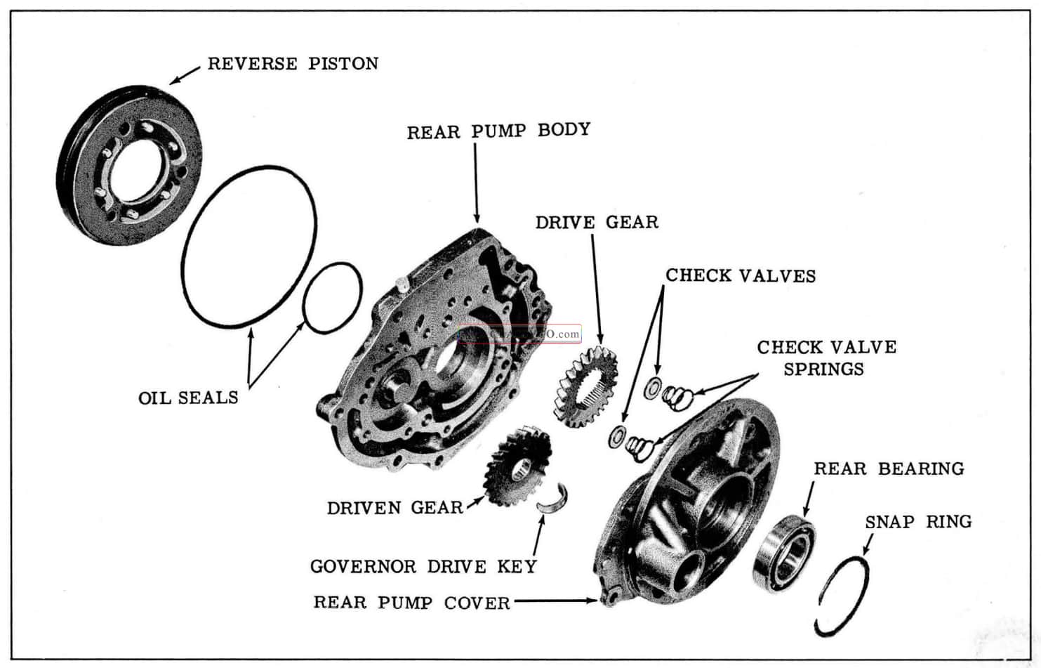
1957 Oldsmobile Rear Oil Pump
- Install 2 rear pump check valves and springs.
- Install rear pump cover and install the 8 cover bolts. Torque 15 to 18ft. lbs.
- Place the inner (small) seal over the rear oil pump hub with the sealing lip down (See Fig. 3-110). Lubricate seal with Hydra-Matic oil.
- Install the reverse piston in the oil pump with the dowel pins aligned with the holes. (This will insure that the inner seal is properly installed.)
- Remove reverse piston and install outer seal (large) on the piston with the sealing lip up. (See Fig. 3-110) Lubricate seal with Hydra Matic oil.
- Position the reverse piston over the dowels in the rear pump and compress the outer oil seal with a blunt screw driver to allow the piston to enter the pump cavity. (Use care so as to not damage seal as piston is being installed.)
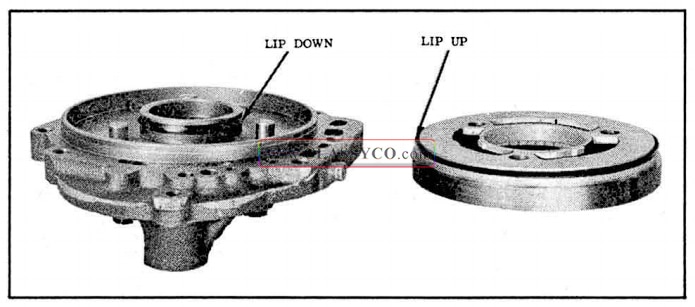
1957 Oldsmobile Installing Reverse Piston Oil Seals
NOTE: Rear bearing will be installed after pump is installed on the transmission.
DISASSEMBLY OF THE GOVERNOR (Fig. 3-111)
- Remove the three cover attaching bolts, then remove cover.
- Remove the two G-2 valve end plate screws, then remove the end plate, sleeve, and G-2 valve.
- Remove the G-2 valve from the sleeve.
- Clean and inspect parts.
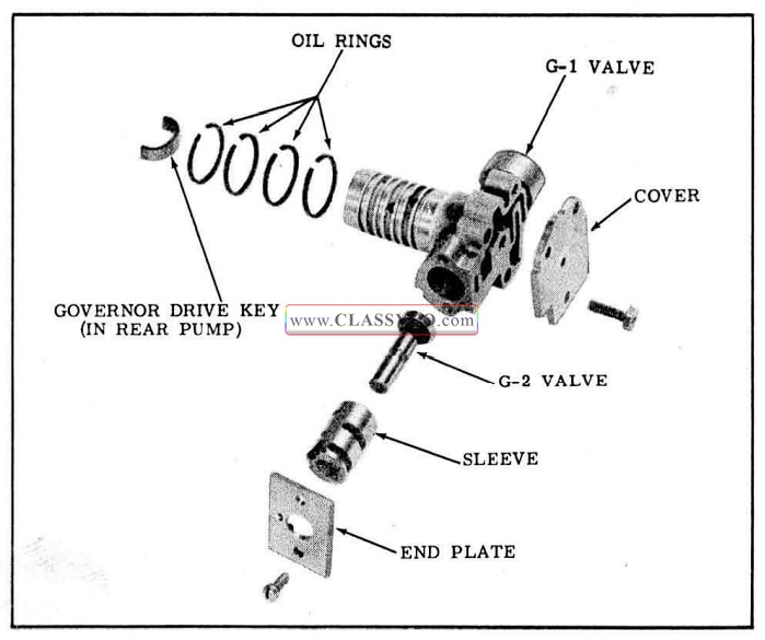
1957 Oldsmobile Governor Assembly
ASSEMBLY OF GOVERNOR
- Install G-2 governor valve into the sleeve, then install the assembly into the governor with locating notches aligned. (See Fig. 3-112)
- Install end plate with the 2 attaching screws.
- Install cover and the 3 cover attaching bolts and lockwashers.
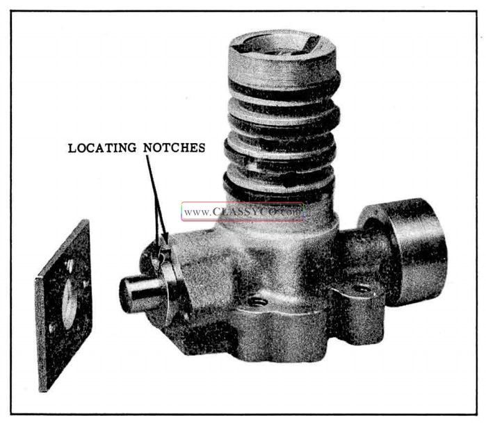
1957 Oldsmobile G-2 Valve Installation
DISASSEMBLY OF ACCUMULATOR AND SERVO
- Pull the servo piston from the servo body.
- Remove 2 opposite accumulator cover screws and install Tool J-6124. (See Fig. 3-115)
- Tighten Tool Bolt against cover to hold cover in place.
- Remove the 3 remaining cover bolts.
- Loosen the tool bolt to relieve the spring tension. Then remove tool, gasket, accumulator piston and accumulator spring.
- Remove the trimmer valve plus retaining pin and plug. (See Fig. 3-114)
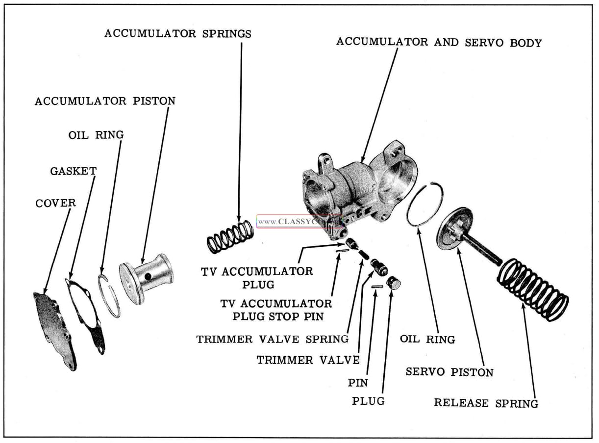
1957 Oldsmobile Accumulator Servo
- Remove the trimmer valve and spring from the accumulator body.
- Remove small diameter TV accumulator plug stop pin and then remove the TV accumulator plug.
- Clean and inspect parts.
ASSEMBLY OF ACCUMULATOR AND SERVO
- Install TV accumulator plug with slotted end out and align slot with stop pin hole.
- Install small diameter TV accumulator plug pin in accumulator body.
- Install trimmer valve spring in the trimmer valve.
- Install trimmer valve and spring into the accumulator body, spring first.
- Install trimmer valve plug and retaining pin.
- Install the accumulator spring into the accumulator body.
- Install accumulator piston into the accumulator body over the spring.
- Install the accumulator cover and gasket on Tool J-6124.
- Install tool with cover and gasket in accumulator body. (See Fig. 3-115)
- Tighten tool bolt slowly while guiding piston and ring into the accumulator.
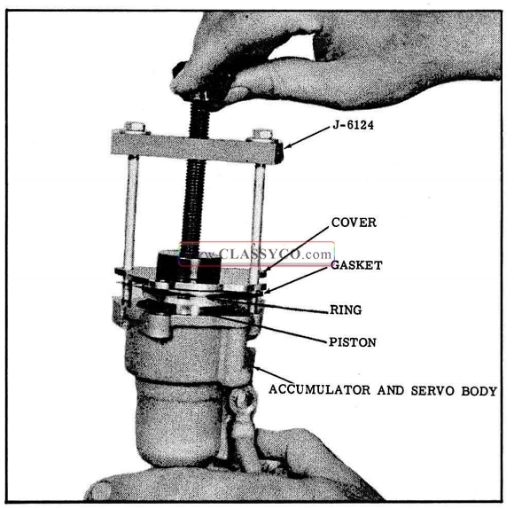
1957 Oldsmobile Installing Accumulator Piston
CAUTION: Do not force piston into accumulator. If ring binds it can be centered with a small screwdriver.
- Install the 3 cover bolts and lockwashers.
- Remove the tool and install the 2 remaining bolts and lockwashers. Torque bolts 6-8ft.lbs.
- Install servo piston into the servo body.
DISASSEMBLY OF THE VALVE BODIES
The control valve assembly consists of 4 individual assemblies bolted to the channel body. In the disassembly and assembly procedure each valve body will be serviced individually.
The names of these individual assemblies are: (See Fig. 3-116)
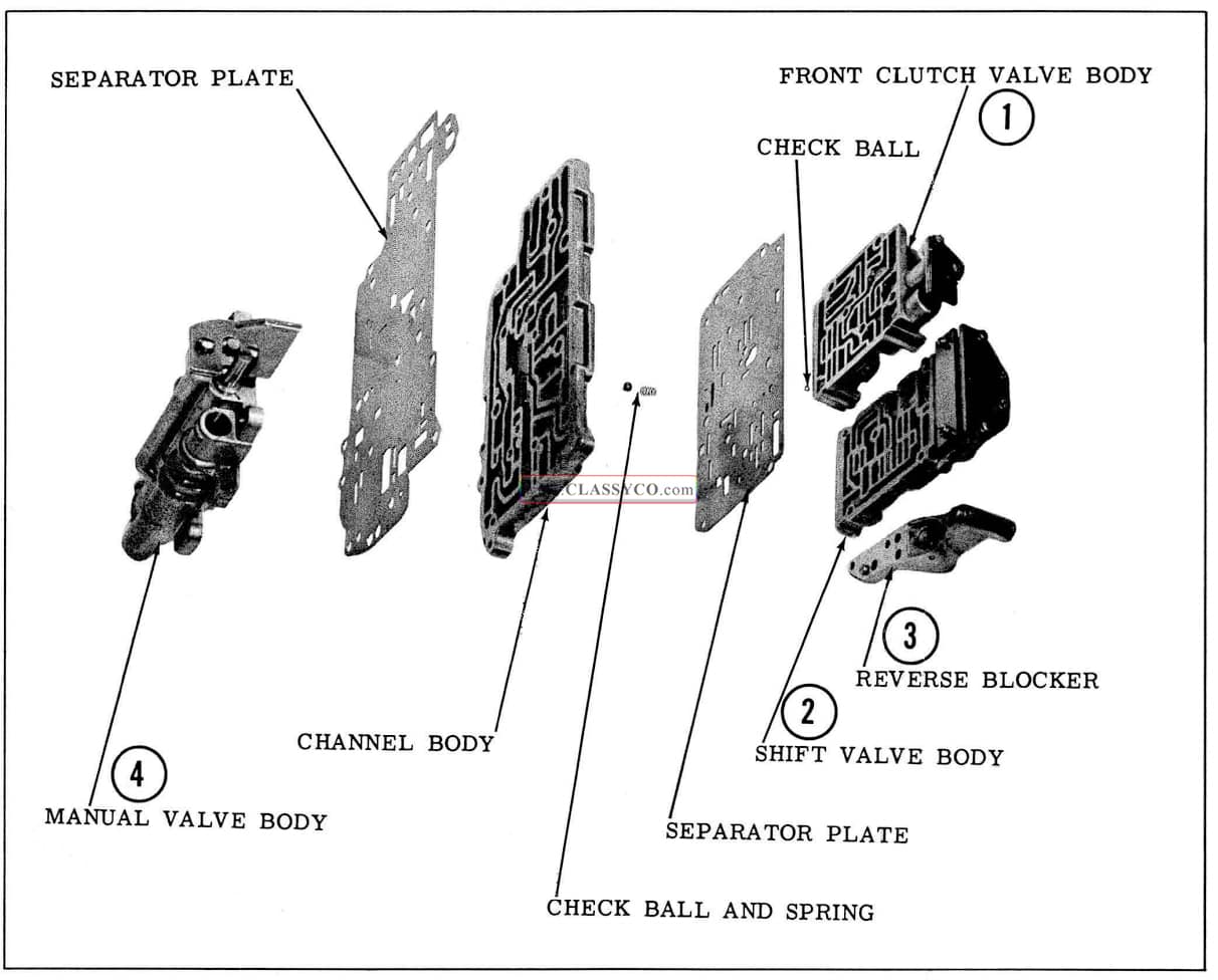
1957 Oldsmobile Main Oil Control Valve Bodies
- Front clutch valve body.
- Shift valve body.
- Reverse blocker.
- Manual valve body.
DISASSEMBLY OF THE FRONT CLUTCH VALVE BODY (Fig. 3-117)
- Remove the 2 front clutch valve body attaching screws, then remove the valve body from the channel body.
CAUTION: Do not lose the ball check when removing the valve body from the channel body.
- Remove the 2 coupling valve plate screws while holding the plate to keep the springs compressed. Then remove the plate.
- Remove the coupling valve -plug and springs.
- Remove the inner and outer limit valve springs.
- Remove the limit valve and washer.
- Remove one half of the coupling valve. The remaining half will be removed from the other end of the valve body.
- Remove the two CENTER screws from the cover plate and hold the cover plate while removing the two end screws.
CAUTION: Cover plate is under spring tension.
- Carefully remove the cover plate.
- Remove the overrun clutch valve and spring.
- Remove second half of the coupling valve.
- Remove the transition valve and spring.
- Clean and inspect parts.
ASSEMBLY OF THE FRONT CLUTCH VALVE BODY (Fig. 3-117)
- Install the transition valve spring into the transition valve.
- Install the transition valve, spring first, into the valve body.
- Install one half of the coupling valve, narrow land first, into the center bore.
- Install overrun clutch valve spring into the overrun clutch valve.
- Install overrun clutch valve, spring first, into the valve body.
- Place the cover plate on the body and hold to compress the springs while installing the two end screws.
- Install the two center screws and tighten the four screws.
- In the opposite end of the valve body, install the limit valve with the stem out.
- Install the limit valve washer.
- Install the coupling valve, stem out.
- Install the coupling valve inner and outer springs. (Install the limit valve springs after the plate has been secured with one screw.)
- Position the coupling valve plug on the springs.
- Push the coupling valve plug into the bore with the plate and install one screw into the center hole. Do not tighten the screw.
- Rotate the plate slightly and install the inner and outer limit valve springs.
- Compress the springs and rotate the plate to retain the springs. Align the plate with the screw hole.
- Install the remaining screw and tighten both screws.
- Align the springs with the plate. A 1/8″ welding rod can be used in the hole over the springs to align the inner spring.
- Install ball check and retain with petrolatum.
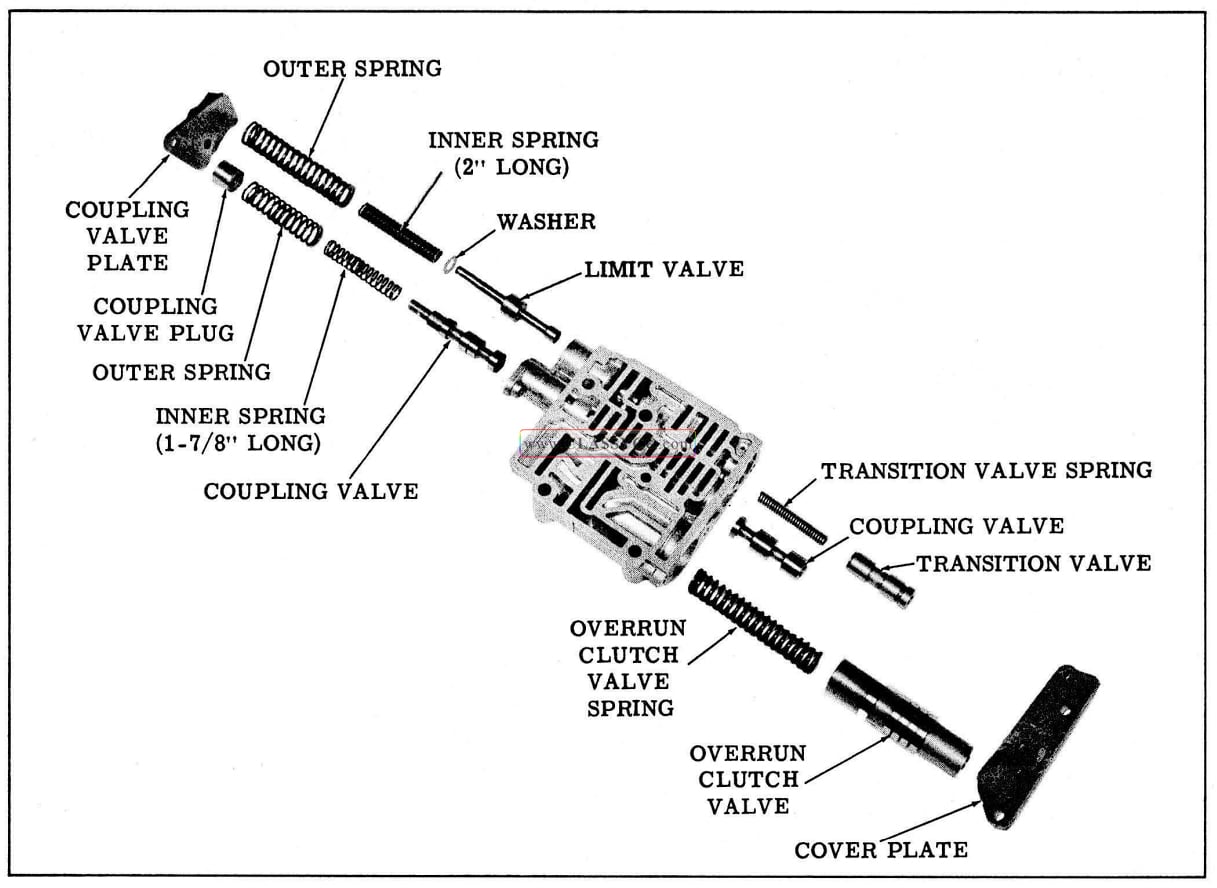
1957 Oldsmobile Front Clutch Valve Body
DISASSEMBLY OF THE SHIFT VALVE BODY (Fig. 3-121)
- Remove the 4 shift valve body attaching screws, then remove the shift valve body from the channel body. (See Fig. 3-118)
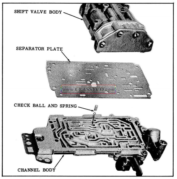
1957 Oldsmobile Shift Valve Body Removal
- Remove the separator plate from the channel body.
- Remove the spring and ball check from the channel body.
- Remove the reed valve from the shift valve body.
- Remove the 4 governor valve end plate attaching screws, then remove the plate. (See Fig. 3-119)
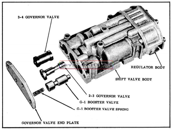
1957 Oldsmobile End Plate and Valve Removal
- Remove the G-1 booster valve spring.
- Remove the 3-4 governor valve.
- Remove the 2-3 governor valve from the center bore.
- Remove the G-1 Booster valve.
- Remove the 2 center screws from the regulator body cover plate. (See Fig. 3-120)
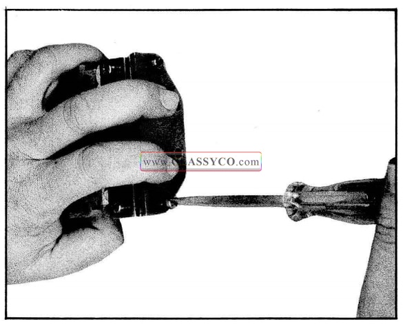
1957 Oldsmobile Regulator Body Removal
- Hold the cover plate and remove the 2 remaining screws.
- Remove the regulator body from the valve body.
- Remove the cover plate from the regulator body.
- Remove the 3-4 regulator valve from the regulator body.
- Remove the 2-3 regulator valve from the regulator body center bore.
- Remove the 3-4 shift valve spring (outer) and the 3-4 regulator spring (inner) from the shift valve body.
- Remove the 2-3 shift valve spring (outer) and the 2-3 regulator spring (inner) from the shift valve body.
NOTE: The 3-4 regulator spring is 5/16″ shorter in free length than the 2-3 regulator spring.
- Remove the neutral clutch valve spring from the neutral clutch valve.
- Remove the 3-4 shift valve from the shift valve body.
- Remove the 2-3 shift valve from the shift valve body.
- Remove the neutral clutch valve from the shift valve body.
- Clean and inspect parts.
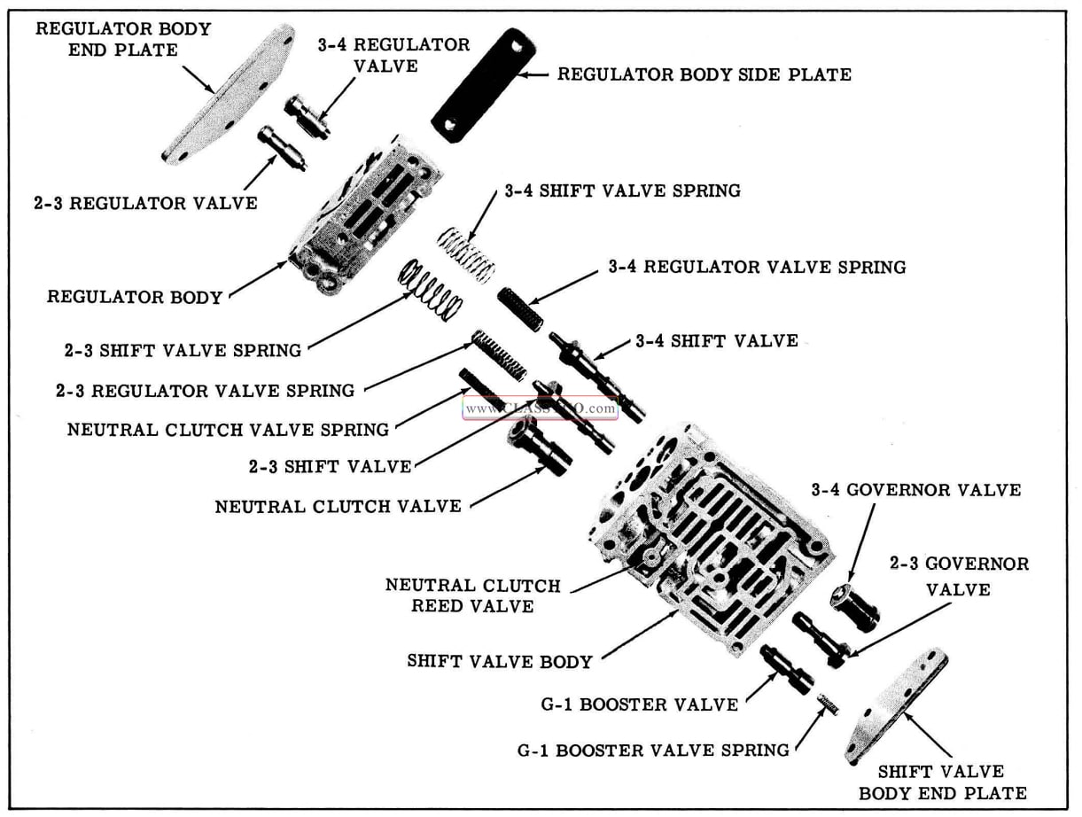
1957 Oldsmobile Shift Valve Body
ASSEMBLY OF THE SHIFT VALVE BODY (Fig. 3-121)
- Install the 2-3 shift valve into the center bore of the shift valve body.
- Install the 3-4 shift valve into the shift valve body.
- Install the neutral clutch valve into the shift valve body.
- Install the 2-3 regulator valve spring (inner) and shift valve spring (outer) on the 2-3 shift valve.
- Install the 3-4 regulator valve spring (inner) and shift valve spring (outer) on the 3-4 shift valve.
- Install the neutral clutch valve spring into the neutral clutch valve.
- Install the 3-4 regulator valve into the regulator body.
- Install the 2-3 regulator valve into the regulator body center bore.
- Position the regulator body end plate on the regulator body and insert 2 screws to hold the cover in alignment.
- Place valve body and regulator body on a flat surface and slide together while guiding springs into place. Then turn both screws in two turns.
- Hold valve body in a vertical position to make sure regulator springs are in place on regulator valves. and shift valve springs are seated on regulator body.
- Push the regulator body against the shift valve body and turn the 2 screws in to hold the assembly.
- Install the 2 remaining screws and tighten all 4 evenly.
- Install the 3-4 governor valve. (small diameter end out)
- Install the 2-3 governor valve into the center bore.
- Install the G-1 booster valve.
- Install the G-1 booster valve spring into the valve.
- Install the governor valve end plate with 4 attaching screws.
- Install neutral clutch reed valve in the valve body. (See Fig. 3-122)
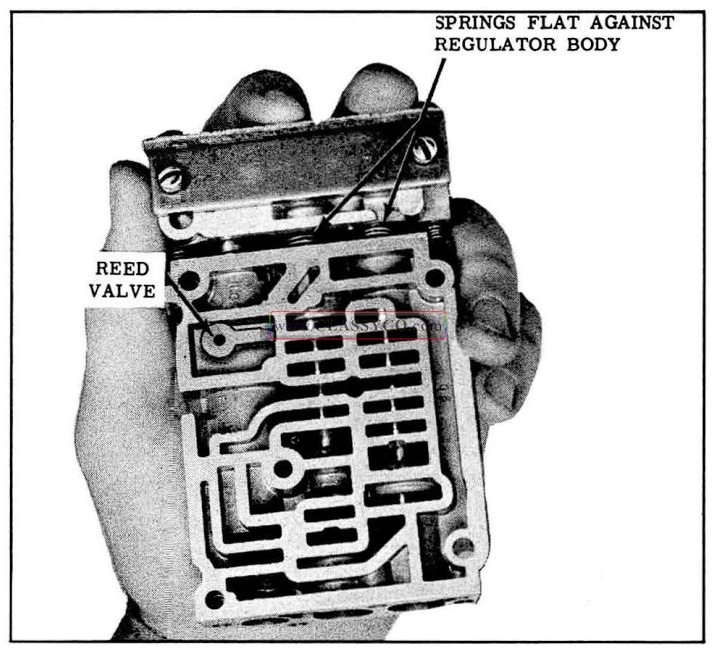
1957 Oldsmobile Installing Regulator Body
DISASSEMBLY OF THE REVERSE BLOCKER (Fig. 3-123)
Remove the 2 reverse blocker body attaching screws. Then remove the reverse blocker assembly.
- Depress the detent plunger. Then remove the retaining clip.
- Remove the detent plunger and spring from the body.
- Remove the spring from the detent plunger.
- Remove the reverse blocker retaining pin.
- Remove the reverse blocker spring. Then remove the reverse blocker piston.
- Clean and inspect parts.
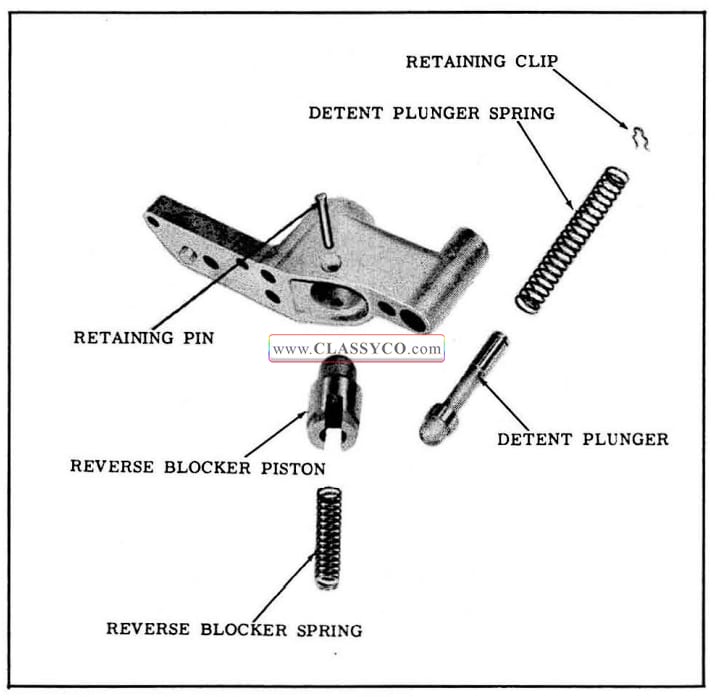
1957 Oldsmobile Reverse Blocker
ASSEMBLY OF THE REVERSE BLOCKER
- Install the reverse blocker piston into the body with the spring bore out.
- Install the reverse blocker spring into the piston.
- Compress the spring with a screwdriver and install the retaining pin from the counterbored side of the body.
- Install the detent plunger spring on the detent plunger.
- Install the spring and detent plunger into the body.
- Depress the detent plunger and install the retaining clip.
DISASSEMBLY OF THE MANUAL VALVE BODY (Fig. 3-124)
- Remove the manual valve from the manual valve body.
- Remove the 6 manual valve body attaching screws and remove the manual valve body from the channel body.
CAUTION: Do not loosen T.V. lever stop pin locking screw. This is calibrated at the factory and NO attempt should be made to change the adjustment.
- Remove the T.V. lever stop.
- Remove the detent valve and spring fro1n the body.
- Remove the T.V. plunger and guide.
- Remove the T.V. plunger from the guide.
- Remove the T.V. spring.
- Remove the throttle valve.
- Remove the throttle valve plug retaining pin.
- Remove the throttle valve plug.
- Remove the separator plate from the channel body.
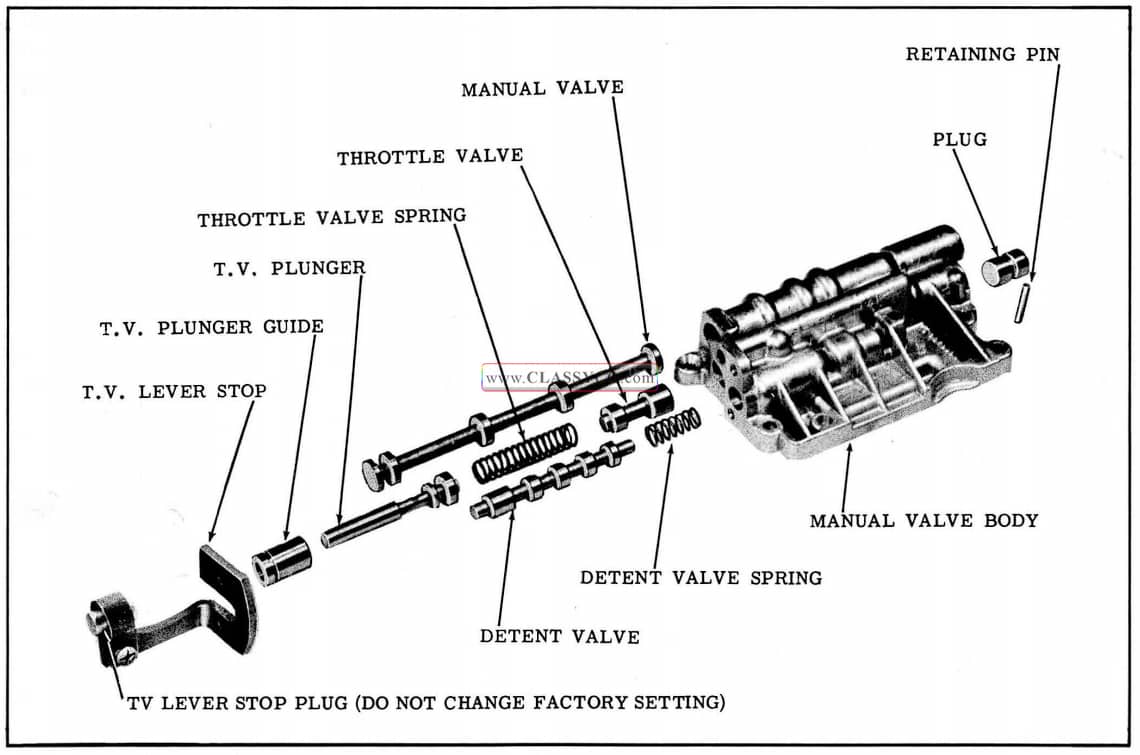
1957 Oldsmobile Manual Valve Body
ASSEMBLY OF THE MANUAL VALVE BODY
- Install the T.V. plug and retaining pin.
- Install throttle valve with stem out. Make sure valve is seated on the plug.
- Install the T.V. spring.
- Install the T.V. plunger guide on the plunger.
- Install the T.V. plunger and guide into valve body.
- Install detent valve spring and detent valve with wide land out.
- Push detent valve into valve body and install T.V. lever stop with the 2 attaching screws.
CAUTION: No attempt should be made to change the factory setting of the T.V. stop plug.
ASSEMBLY OF INDIVIDUAL VALVE BODIES TO THE CHANNEL BODY
- Position the long separator plate on the check valve side of the channel body. (See Fig. 3-125)
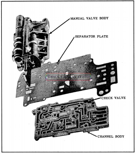
1957 Oldsmobile Manual Valve Body Installation
- Position the manual valve body on the separator plate and install the 6 attaching screws finger tight.
- Turn the channel body over and position the reverse blocker body on the manual body end of the separator plate. Install the 2 attaching screws finger tight.
- Install the check ball and spring into the ball seat in the channel body. (See Fig. 3-126)
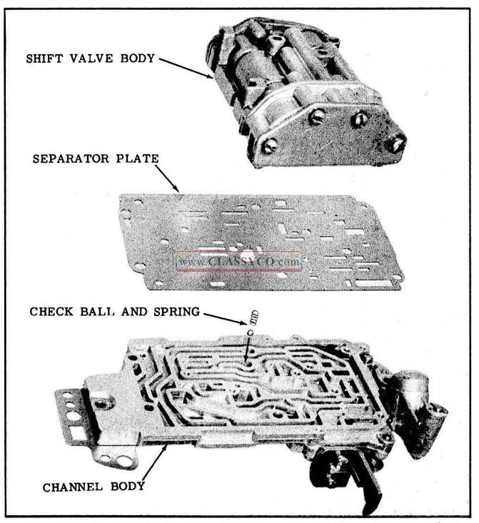
1957 Oldsmobile Shift Valve Body Installation
- Position separator plate on the channel body.
- Position the shift valve body on the separator plate and install the 4 attaching screws finger tight.
- Make sure the small check ball seats in the front clutch valve body.
- Position the front clutch valve body on the separator plate and install the 2 attaching screws finger tight.
- Use 4 valve body to case attaching bolts to align channel body, separator plates and valve bodies.
- Tighten all valve body attaching screws. (Total 14)
- Install manual valve in the shift valve body.
DRIVEN TORUS DISASSEMBLY
- Remove the cotter pin from hub of the driven torus.
- Remove the torus check valve and spring. (See Fig. 3-127)
- Clean and inspect parts.
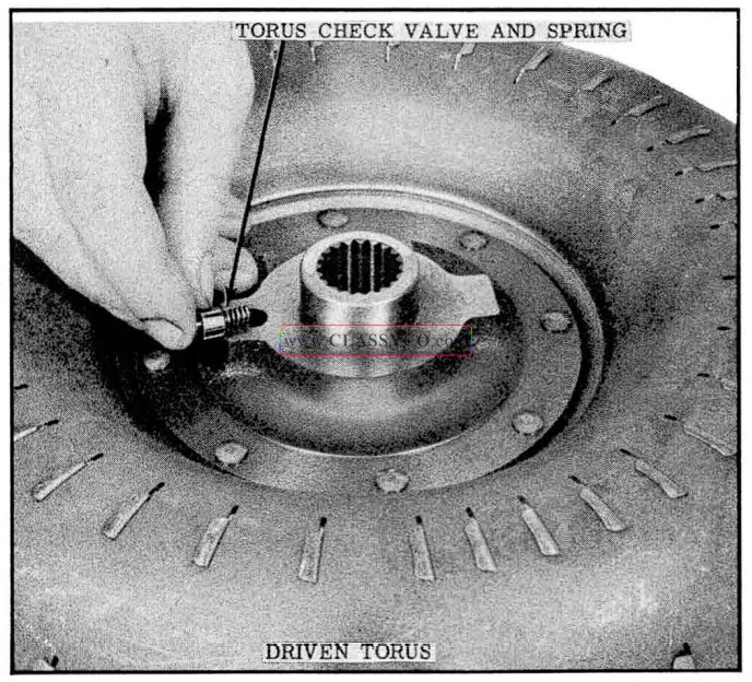
1957 Oldsmobile Driven Torus Check Valve
ASSEMBLY OF THE DRIVEN TORUS
- Apply petrolatum on the spring, then install the spring into the check valve.
- Install valve into the driven torus, spring first.
- Install cotter pin to retain the valve.
DRIVE TORUS
The drive torus requires no service other than replacement when damaged.
FLYWHEEL HOUSING
FLYWHEEL HOUSING SEAL REMOVAL (Fig. 3-128)
- Place a blunt chisel behind the lip of the seal and drive the seal out of the housing.
CAUTION: Do not damage the bushing in the housing.
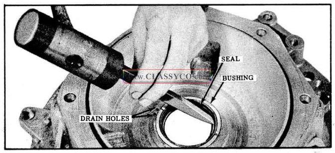
1957 Oldsmobile Flywheel Housing Seal Removal
FLYWHEEL HOUSING SEAL INSTALLATION
- Apply a light coat of P.O.B. No. 3 sealer (Part No. 557622) to the outer diameter of a new seal.
- Place the seal (lip down) on housing.
- Inspect seal installing Tool J-6118 for nicks or sharp edges that might damage the lip of the seal. A hone can be used to clean up any sharp edges on the tool.
- Place seal installing Tool]-6118 into seal and drive seal into place. (See Fig. 3-129). Remove tool from seal.
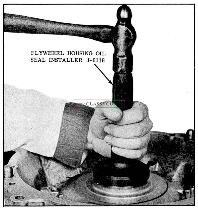
1957 Oldsmobile Seal Installation
- Support the center of the flywheel housing on a wood block (approximately 4″ x 4″ x 4″) and stake seal into place with a center punch. (See Fig. 3-130)
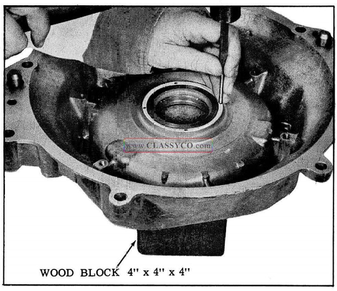
1957 Oldsmobile Staking Housing to Retain Seal
NOTE: 4 evenly spaced punch marks will be sufficient.
FLYWHEEL
The flywheel requires no service other than replacement when necessary.
ASSEMBLY OF THE TRANSMISSION
REVERSE UNIT AND REAR OIL PUMP
- Install reverse planet carrier on the output shaft. Lifting up on the output shaft will allow planet pinions to engage with the reverse sun gear. (See Fig. 3-131)
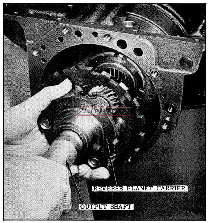
1957 Oldsmobile lnstalling Reverse Planet Carrier
- Install reverse carrier snap ring on the output shaft.
- Install reverse stationary cone lock in the transmission case and retain with petrolatum. (See Fig. 3-132)
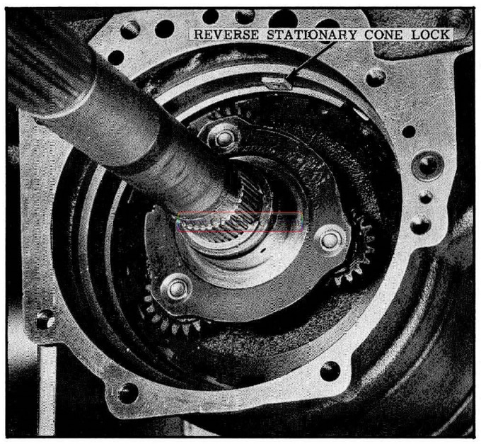
1957 Oldsmobile Reverse Stationary Cone Lock
- Install reverse stationary cone in the case. Make sure cone seats on the shoulder in the case.
- Install reverse clutch release spring over the output shaft and against reverse carrier with the fingers out. (See Fig. 3-133)
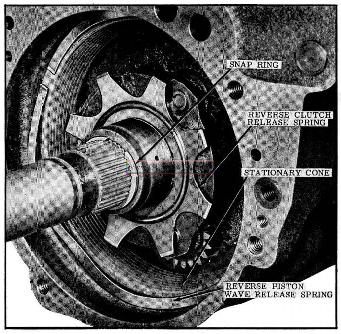
1957 Oldsmobile Reverse Release Springs
- Install reverse piston wave release spring.
- Install the reverse internal gear by turning to engage planet pinions. (See Fig. 3-134)
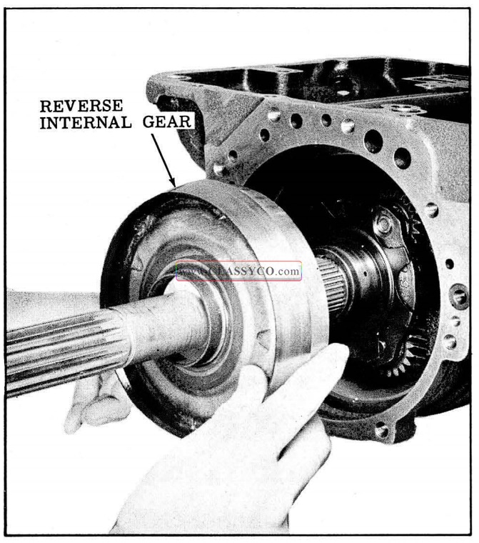
1957 Oldsmobile Installing Reverse Internal Gear
- Install thrust washer on reverse internal gear.
- Install gasket on rear pump and retain with petrolatum.
- Install rear pump assembly on transmission case. Install locating screw and attaching bolt. (See Fig. 3-135)
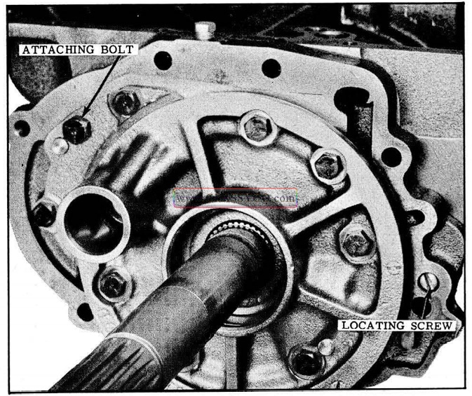
1957 Oldsmobile Rear Oil Pump (2)
NOTE: Pump should be held against the case until locating screw and attaching bolt are tightened.
- Remove Tool J-6135, then install rear bearing on output shaft with rear bearing installing Tool J-6133. (See Fig. 3-136)
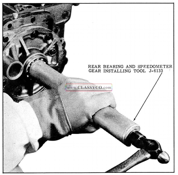
1957 Oldsmobile Installing Rear Bearing
- Install rear bearing retaining ring into the rear pump. (See. Fig. 3-137)
- Install rear bearing snap ring on the output shaft. (See Fig. 3-137)
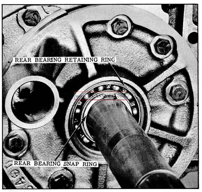
1957 Oldsmobile Snap Ring Installation
CHECK MAIN SHAFT END PLAY
- Remove collar from Tool J-6127 and install on mainshaft. (See Fig. 3-138)
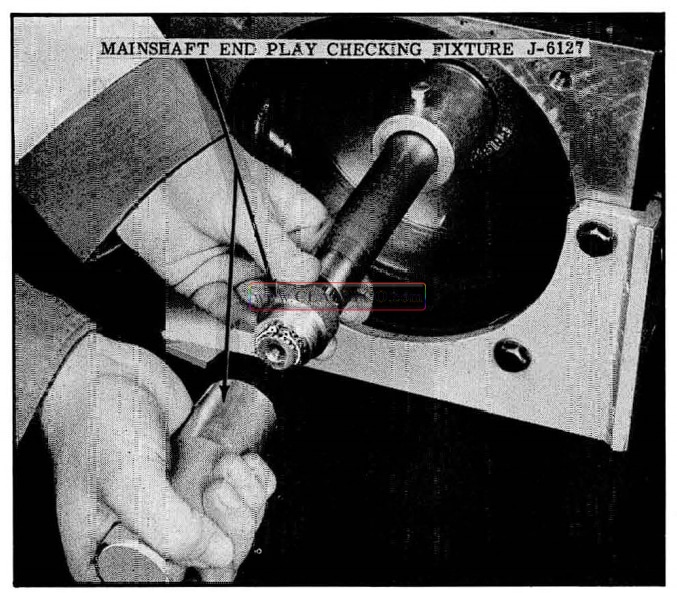
1957 Oldsmobile Mainshaft End Play Tools
- Install Tru-arc ring on mainshaft then install body of Tool J-6127 and tighten.
- Install Tool J-6126 on front of transmission and install dial indicator. (See Fig. 3-139)
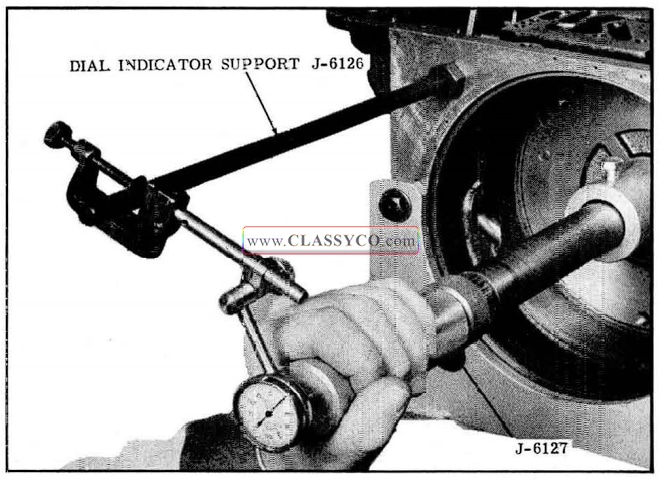
1957 Oldsmobile Checking Mainshaft End Play (2)
- Check mainshaft end play. If not within .004″ to .018″ the selective washer in the reverse drive flange is incorrect and will need to be changed.
- Remove tools from the transmission.
SPEEDOMETER DRIVE GEAR AND EXTENSION HOUSING
- Install the speedometer d rive gear on the output shaft with Tool J-6133 and use Gauge J-6134 to locate gear on the shaft. (See Fig. 3-140)
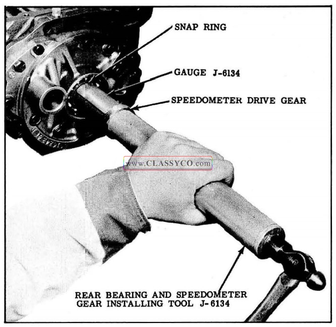
1957 Oldsmobile Installing Speedometer Drive Gear
- Install governor into rear pump with the ring gaps on top, and lubricate rings with Hydra-Matic oil.
- Turn output shaft to make sure governor and drive key are engaged.
- Install a new rear extension housing gasket on the rear oil pump and retain with petrolatum.
- Install the extension housing and the 8 attaching bolts. Torque 25 to 30 ft. lbs.
- Apply seal lubricant Part No. 567196 to the sealing lip of a new rear seal.
- Apply a light coat of P.O.B. No. 3 Sealer (Part No. 557622) to the outer diameter of the seal.
- Install seal into the extension housing using rear seal installing Tool J -5154.
- Install breather tube into rear pump and install attaching screw into transmission case.
- Install companion flange on output shaft using Installing Tool 6505. (See Fig. 3-141)
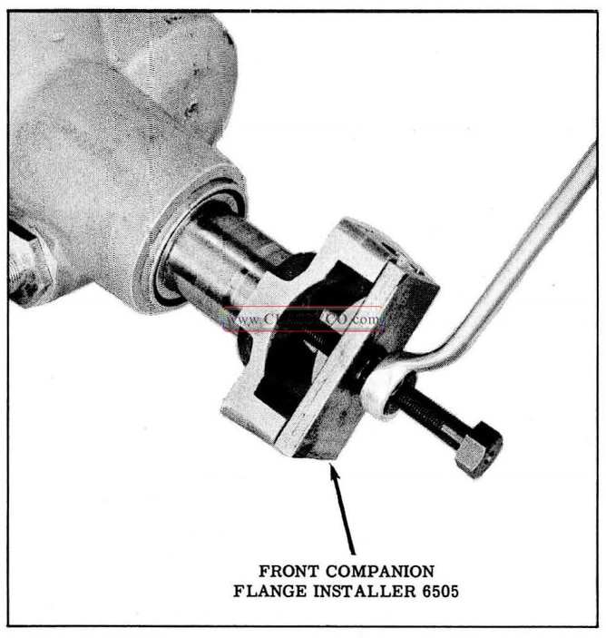
1957 Oldsmobile Installing Companion Flange
OVERRUN CLUTCH AND FRONT PUMP
- Turn transmission so that intermediate shaft is up.
- Install bronze thrust washer with lugs aligned over sprag inner race on the front pump. Retain thrust washer in position with petrolatum. (See Fig. 3-142)
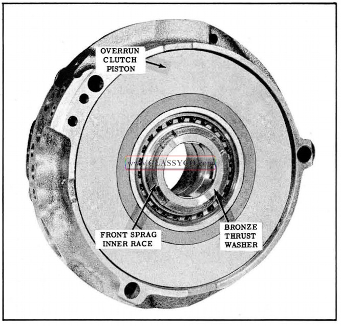
1957 Oldsmobile Bronze Washer Installation
- Install overrun clutch plate using Hydra-Matic fluid to retain clutch plate to overrun clutch piston. Align plate with lugs on washer and lugs on sprag inner race.
- Install overrun clutch wave release spring in the front pump. (Tension against the front pump body will retain the wave release spring.) (See Fig. 3-143)
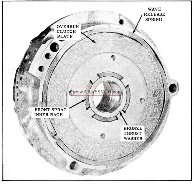
1957 Oldsmobile Wave Release Spring Installation
- Lubricate lock-type oil ring on intermediate shaft with Hydra-Matic oil.
- Install Tools J -6125 into front pump and in stall pump into case with intake pipe hole aligned with hole in the case. (See Fig. 3-144)
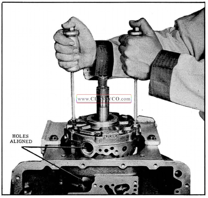
1957 Oldsmobile Installing Front Pump
- Install the 3 front pump to case support attaching bolts and tighten. Then back off approximately 1/4 turn. Do not torque tighten until after locating screw has been installed and tightened. Remove slide hammers.
- Install the 2 front pump cover attaching bolts.
- Torque the 4 front pump cover attaching bolts 15 to 18 ft. lbs.
- Install the 2 oil cooler sleeves with “O” rings facing into the pump.
- Turn transmission to a horizontal position.
- Install front pump locating screw finger tight. (See Fig. 3-145)
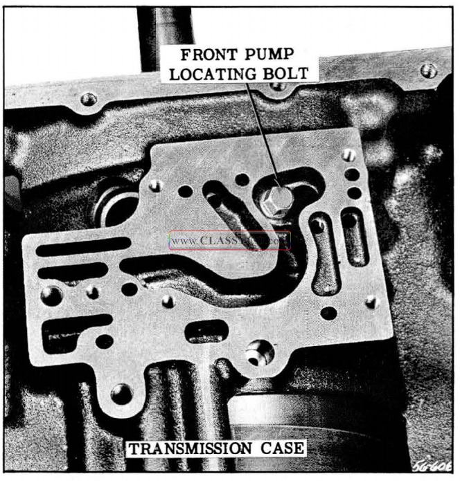
1957 Oldsmobile Front Pump Locating Bolt
- While applying approximately 80 P.S.I. air pressure to the neutral clutch passage, tighten front pump locating screw. (See Fig. 3-146) Torque 10 to 13 ft. lbs.
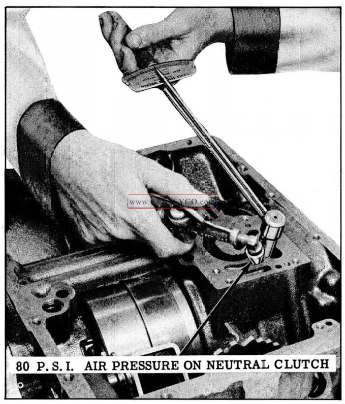
1957 Oldsmobile Tightening Front Pump Locating Bolt
NOTE: Air pressure on the neutral clutch will properly position front pump and neutral clutch with oil passages in the case. This is necessary to prevent an internal oil leak at this point. The pump mounting bolts were left loose so that the locating screw would draw the pump toward the case.
- Torque the 3 front pump to case support attaching bolts 20 to 25 ft. lbs.
- Install front pump pressure regulator valve and spring.
- Install the pressure regulator plug into the case. Torque 3 to 6 ft. lbs.
MAIN OIL CONTROL VALVE ASSEMBLY, SERVO AND ACCUMULATOR
- Position the oil control valve body on the case with the throttle lever between the T.V. plunger and the stop, and the shift lever pin engaged with the manual valve. (See Fig. 3-147)
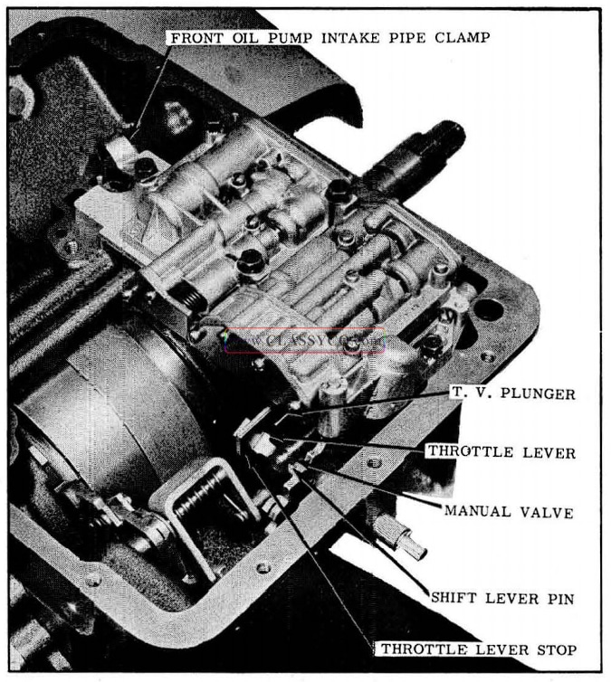
1957 Oldsmobile Main Oil Control Valve Body Installation
- Install the 6 attaching bolts finger tight.
- Position the low band release spring on the servo piston. Then install the servo and accumulator assembly with 3 attaching bolts. (See Fig. 3-148) Torque bolts 23 to 28ft. lbs.
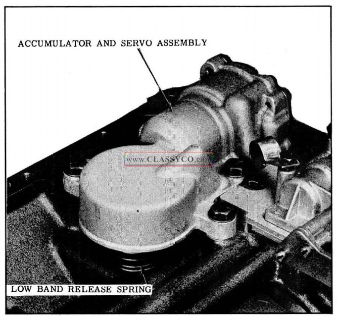
1957 Oldsmobile Accumulator and Servo Installation
NOTE: Make sure release spring is centered around servo piston stem.
- Torque main oil control valve body attaching bolts 6 to 8 ft. lbs., except the one with the front pump pipe clamp.
- Install a new front pump intake pipe “O” ring into the front pump and lubricate with Hydra-Matic oil.
- Install the front pump intake pipe into the front pump and under the clamp. Torque clamp bolt 6 to 8 ft. lbs.
- Install a new rear pump intake pipe “O” ring into the case and lubricate with Hydra-Matic oil.
- Install rear pump intake pipe into the screen. Then install the screen on the front pump intake pipe and push rear pump intake pipe into the case.
- Install oil pan gasket, oil pan and attaching bolts.
FRONT UNIT END PLAY
To control end play of the front unit, a open end type selective spacer is used on the front unit coupling driven shaft. The spacer is between the front unit coupling drive torus hub and the front unit internal gear.
The following method is used to determine the proper selective spacer to use.
- Turn transmission so that the intermediate shaft is up.
- Install front unit coupling with drive lugs down. Turn driven torus shaft counter-clock wise until lugs engage with front sprag inner race. When lugs are engaged the shaft cannot be turned counter-clockwise.
- Turn front unit coupling until lugs on cover hub engage with front pump rotor.
- Place a No. 1 selective spacer (.0695″ to .0705″) on driven torus shaft. (See Fig. 3-149)
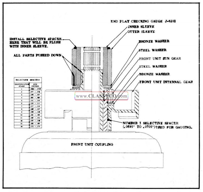
1957 Oldsmobile Front Unit End Play
This will be used as a gauge spacer.
- Install front unit internal gear and bronze thrust washer (with 2 lugs).
- Install steel spacer (splined to shaft) against bronze thrust washer in internal gear.
- Install front unit sun gear.
- Install steel washer, then the bronze washer.
- Push on intermediate shaft and front unit sun gear bronze washer to make sure all parts are down as far as possible.
- Install front unit end play checking gauge J-6282 (splined end down).
- Push down on inner and outer sleeves of gauge to make sure gauge is seated.
There are 14 selective spacers available and are marked 1 through 14. There is a variation in thickness of .002″‘ in spacers with the same number, and a variation of .006″ to 010″ in spacers of consecutive numbers.
- Select a spacer that will be flush with inner sleeve of gauge when installed on outer sleeve.
The number 1 selective spacer used to properly position the parts for gauging will be replaced by the spacer determined by the gauge when assembling the transmission.
- Remove selective spacer from top of gauge and save to be used when assembling the transmission.
- Remove the gauge, bronze washer, steel washer, sun gear, steel washer, internal gear, and bronze washer from the transmission.
- Remove the No. 1 selective spacer used for gauging.
- Lift the front unit coupling from the transmission.
FLYWHEEL HOUSING TORUS COVER, TORUS MEMBERS AND FLYWHEEL (Fig. 3-150)
- Remove the transmission and holding fixture from the mounting fixture and place the assembly on the bench.
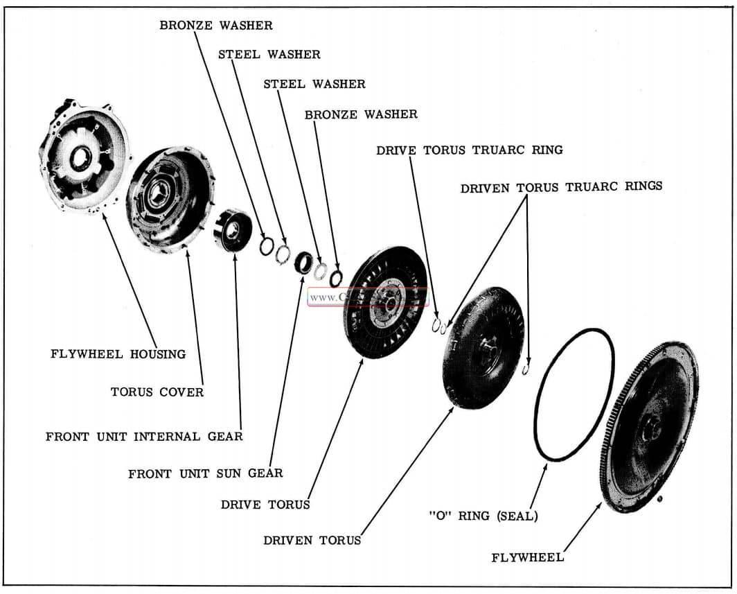
1957 Oldsmobile Torus Assembly
- Remove the holding fixture from the transmission.
- Install oil cooler adapter gasket and adapter (outlets facing front of transmission) with 2 bolts and copper washers. Torque 15 to 18 ft. lbs.
- Install front unit coupling by turning driven torus shaft counter-clockwise to engage drive lugs in front sprag. Turn front unit coupling to engage lugs with the pump rotor.
- Install seal and bushing protector Tool J-6119 over the shafts on the front of the transmission.
- Install a new flywheel housing “O” ring on the housing. Make sure “O” ring is seated in the groove. (See Fig. 3-151)
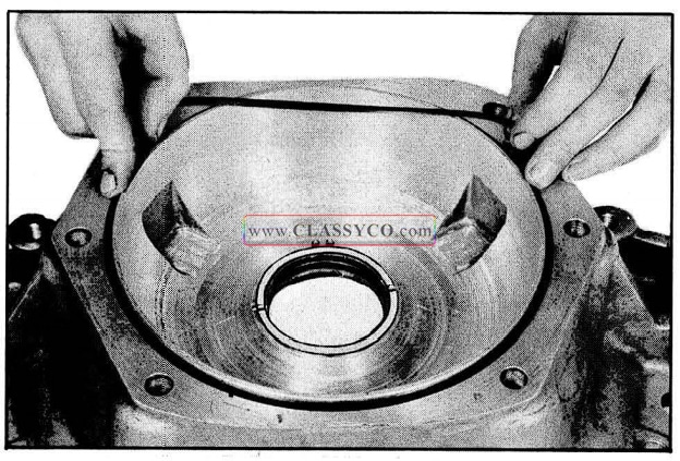
1957 Oldsmobile Installing Flywheel Housing O Ring
- Install flywheel housing with the 6 attaching bolts and washers. Tighten evenly and torque 40 to 50 ft. lbs.
- Remove the seal and bushing protector Tool J-6119.
- Lubricate hub of torus cover with seal lubricant Part No. 567196. Then install the cover using care to prevent damage to the seal.
- Install the selective spacer, determined by the gauge, on the front unit coupling shaft. (See Fig. 3-152)
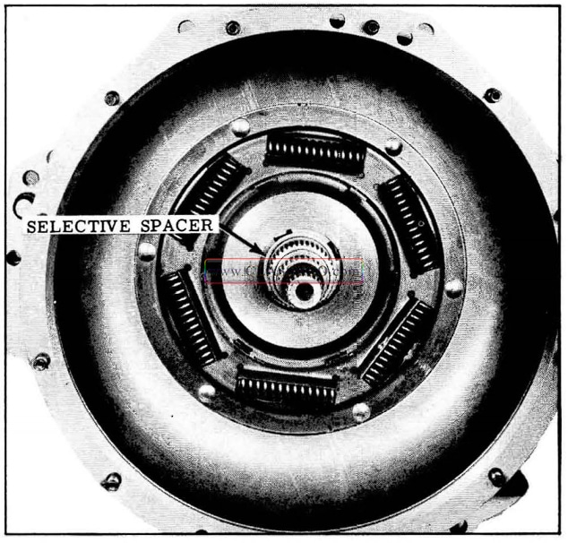
1957 Oldsmobile Selective Spacer
- Install internal gear into the torus cover, indexing with the drive lugs. (See Fig. 3-153)
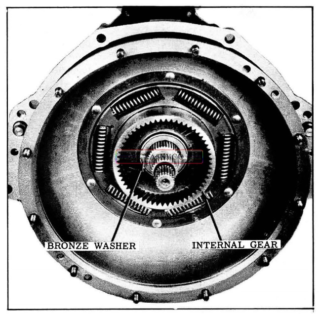
1957 Oldsmobile Internal Gear and Bronze Washer Installation
- Install bronze washer in internal gear, and in stall steel washer (splined to shaft) and front unit sun gear.
- Install steel washer against the sun gear. Then install the bronze washer.
- Install drive torus on the intermediate shaft, and turn to engage planet pinions.
- Install Tru-arc ring on the intermediate shaft.
- Install Tru-arc ring in second groove on the mainshaft.
- Install driven torus on mainshaft, lifting up to prevent damage to the bushing in the torus member.
- Install Tru-arc ring on the mainshaft.
- Install a new “O” ring on the flywheel on out side of retainer. Make sure “O” ring is not twisted.
- Position flywheel over torus dowels. Be sure that large dowel indexes with large hole in fly wheel. Install 8 attaching nuts, omitting numbers 1, 4, 7, 10 (numbering clockwise from either dowel). Tighten evenly, then torque 15 to 20 ft. lbs.
NOTE: 4 flywheel bolts evenly spaced are for mounting flywheel to flexplate on back of the crankshaft.
SERVICING THE OIL COOLER
In the event of a major transmission failure, where particles of metal have been carried with the oil throughout the units of the transmission, it will be necessary to flush out the oil cooler and connecting lines. The oil cooler is located in the radiator lower tank. (See Fig. 3-154) It is a sealed container providing a passage for oil to flow from the inlet to the outlet. Clean solvent can be flushed through the cooler with air pressure. (An engine desludge gun may be used). The cooler should be back-flushed first through the return line to remove all foreign material possible. Then flush through the inlet line and finish by flushing through the return line. Clean remaining solvent from cooler with compressed air applied to the return line and flush with Hydra-Matic Oil.
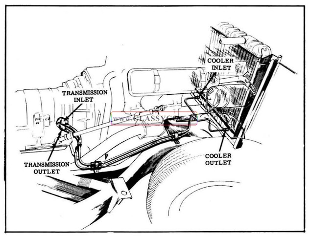
1957 Oldsmobile Oil Cooler Details
MINOR SERVICE ADJUSTMENTS
Throttle linkage has been redesigned for 1957 so that the following linkage adjustments must be made WITH THE CARBURETOR THROTTLE VALVES IN THE CLOSED POSITION.
- Carburetor Rod, Throttle Lever to Auxiliary Bellcrank Adjustment
- Lower Throttle Rod Adjustment
- Upper Throttle Rod Adjustment
The following adjustments must be made with the choke completely off, and the Carburetor throttle valves in the slow idle position.
- Throttle Stop Screw Adjustment
- Bellcrank to Dash Clearance
- Accelerator Pedal Height.
The throttle return check adjustment must still be made after setting fast idle. Since throttle control adjustments are made with the carburetor throttle valves in the closed bore position, later slow idle adjustments will not change the relationship between the carburetor and transmission.
THROTTLE RETURN CHECK ADJUSTMENT (See A, Fig. 3-155)
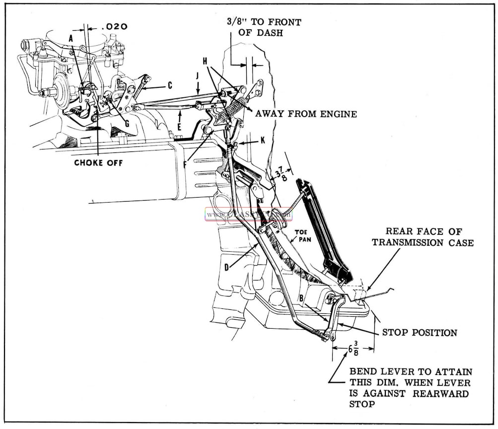
1957 Oldsmobile Throttle Linkage Adjustment
- Start engine and allow it to reach normal operating temperature.
- Set fast idle screw on high step of fast idle cam.
- With transmission in neutral, adjust fast idle screw to obtain engine speed of 1500 R.P.M.
- With the engine not running, rotate the fast idle cam so that the fast idle screw rests on the high step on the cam.
- Adjust throttle return check contact screw, USING TWO WRENCHES TO PREVENT DAMAGE TO RETURN CHECK DIAPHRAGM until clearance between contact screw and throttle lever is .020″. (See Fig. 3-156)
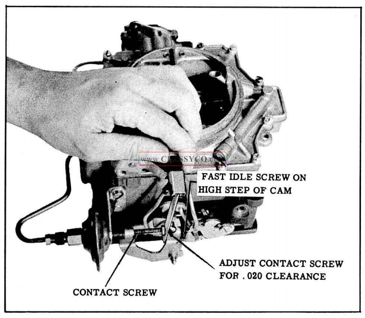
1957 Oldsmobile Adjusting Throttle Return Check
THROTTLE LINKAGE ADJUSTMENTS ADJUST THROTTLE LEVER AT SIDE OF TRANSMISSION (See B, Fig. 3-155)
- Raise car and remove clip and throttle rod “D” from throttle lever at side of transmission case.
- Place throttle lever gauge J-6344 against machined surface of rear of transmission case. While holding throttle lever at the end of its rearward travel, the gauge rod should enter hole in throttle lever. (See Fig. 3-157)
- If gauge rod does not enter throttle lever hole, bend lever with Tool 6373-01, recheck, and install throttle rod and clip.
NOTE: Tool J-6373 may be revised by cutting 5/8″ from the top of the tool (See insert in Fig. 3-157)
- Lower car.
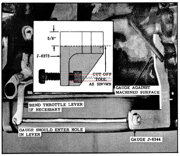
1957 Oldsmobile Checking Throttle Lever Adjustment
ADJUST CARBURETOR ROD, THROTTLE LEVER TO AUXILIARY BELLCRANK (See C, Fig. 3-155)
- Start engine, remove air cleaner and block choke valve open. Install THROTTLE RETURN CHECK HOLDING TOOL J-6342 (See insert in Fig. 3-158 for Tool revision) to hold plunger away from throttle lever. (See Fig. 3-158) Turn off ignition switch and BACK OUT SLOW IDLE ADJUSTING SCREW UNTIL CARBURETOR THROTTLE VALVES ARE COMPLETELY CLOSED. In a true closed bore position, clearance will be present at the end of the fast idle screw, slow idle screw, and the throttle return check plunger.
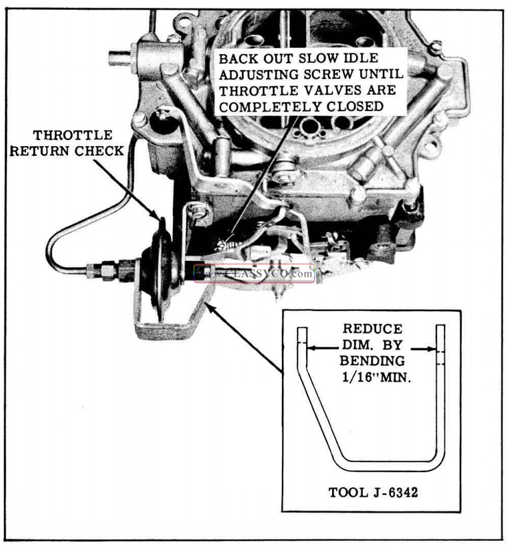
1957 Oldsmobile Throttle Return Check Holding Tool
- Remove retainer clips from carburetor throttle lever and belle rank lever. Do not remove carburetor rod.
- Place gauge No. 33-67 against rod with hole in gauge over pin on carburetor throttle lever. (See Fig. 3-159)
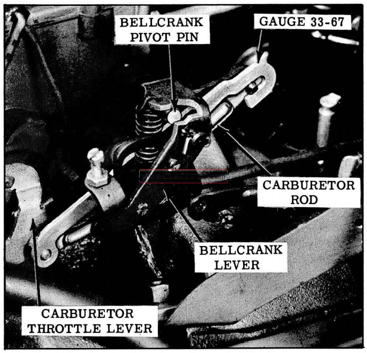
1957 Oldsmobile Checking Carburetor Throttle Lever
- With the gauge held up against bellcrank pivot pin, the open end of the tool should fit over the pin on the bellcrank lever freely without rotation of the bellcrank.
- If pin does not enter gauge freely, remove rod and place in a vise and increase or decrease the bend as necessary. Install the rod, recheck with gauge and replace retainer clips.
ADJUST LOWER THROTTLE ROD (See E, Fig. 3-155)
- Loosen jam nut and remove both clevis pins from bellcrank.
- With both bellcrank and transmission lower throttle rod held against their rearward stops, adjust lower throttle rod clevis so that the pin will enter freely into holes in clevis and the bellcrank. (See Fig. 3-160)
- Install cotter pin and tighten jam nut.
ADJUST UPPER THROTTLE ROD (See E, Fig. 3-155)
- With bellcrank “F” against its stop and upper throttle rod “E” pulled lightly toward rear of engine to take up slack, adjust clevis on upper rod so that pin enters freely into holes in clevis and bellcrank. (See Fig. 3-160)
- Install cotter pin and tighten jam nut.
- Set carburetor slow idle speed at 425 R.P.M. in “D” position. This will pull T.V. bellcrank forward from the stop and provide proper T.V. adjustment. On air conditioned cars slow idle speed must be set with compressor running.
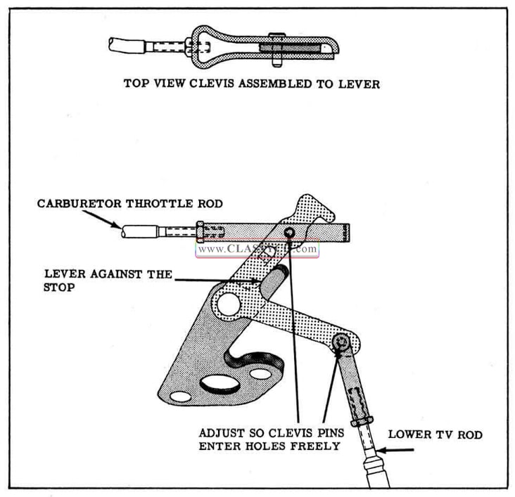
1957 Oldsmobile Adjusting Lower and Upper Throttle Rods
ADJUST THROTTLE STOP SCREW (See G, Fig. 3-155)
- Loosen jam nut and back out stop screw several turns. Hold choke wide open and pull forward on bellcrank “H” on dash until throttle valves are wide open, then go beyond to the point of maximum transmission lever travel. This point is a matter of feel – do not bend or stretch linkage beyond this point.
- With throttle held in this position, adjust stop screw “G” to just touch the tang on the down shift lever.
- Allow the throttle valves to return to a closed position, then turn screw “G” in 1-1/2 to 2 turns and tighten jam nut. (See Fig. 3-161)
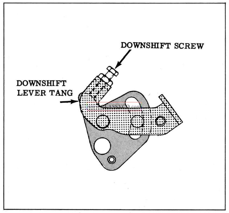
1957 Oldsmobile Throttle Stop Screw Adjustment
ADJUST BELLCRANK TO DASH CLEARANCE (See H, Fig. 3-155)
If clearance between bellcrank and dash is not 3/8″ plus or minus 1/32 ” adjust as follows:
- Loosen jam nut on rod assembly “J” remove clip and clevis from pin on bellcrank “H”.
- Adjust rod end so there is 3/8″ clearance between bellcrank “H” and front side of dash. (See Fig. 3-162)
- Install rod end and clip with open side of rod end toward outside of car, and tighten jam nut.
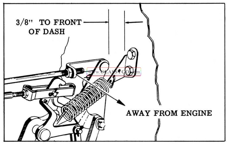
1957 Oldsmobile Adjusting Bellcrank to Dash Clearance
ADJUST ACCELERATOR PEDAL HEIGHT
- Position 3-7/8″ wooden block between bottom of accelerator pedal and top of floor mat retainer. (See Fig. 3-163)
- Remove clip and rod assembly “K” from bellcrank “H”.
- Loosen jam nut and adjust rod assembly “K” so that hole just slides over pin on bellcrank with accelerator pedal touching gauge block.
- Install rod end on bellcrank, with open side towards outside of car. Tighten jam nut and remove gauge block from pedal.
- Lubricate linkage pivot points with light engine oil.
- Remove throttle return check holding tool J -6342, unblock choke, and install air cleaner.
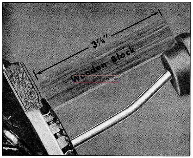
1957 Oldsmobile Accelerator Pedal Adjustment
MANUAL LEVER ADJUSTMENT
- Set transmission manual lever in neutral detent position.
- Disconnect manual rod from lower shift lever.
- Hold lower shift lever upward so selector lever is positioned against stop in upper steering column.
- Adjust manual rod end so pin will enter ap proximately 1/8″ into lower shift lever bushing with selector lever against stop. (See Fig. 3-164)
- Tighten clevis lock nut and connect manual rod to lower shift lever.
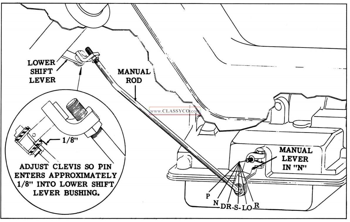
1957 Oldsmobile Manual Lever Adjustment
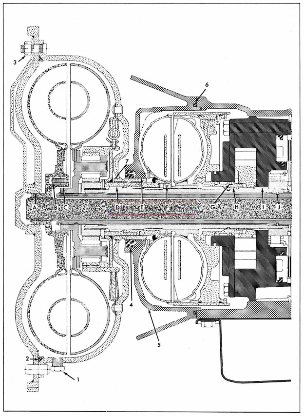
1957 Oldsmobile Oil Leak Diagnosis
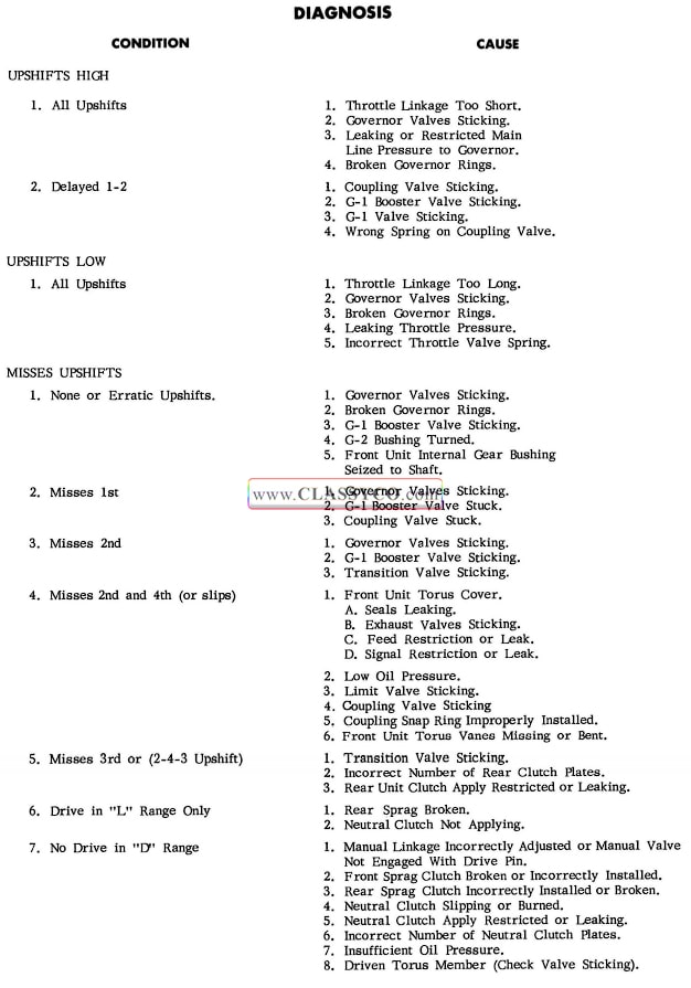
1957 Oldsmobile Hydra-Matic Diagnosis 1
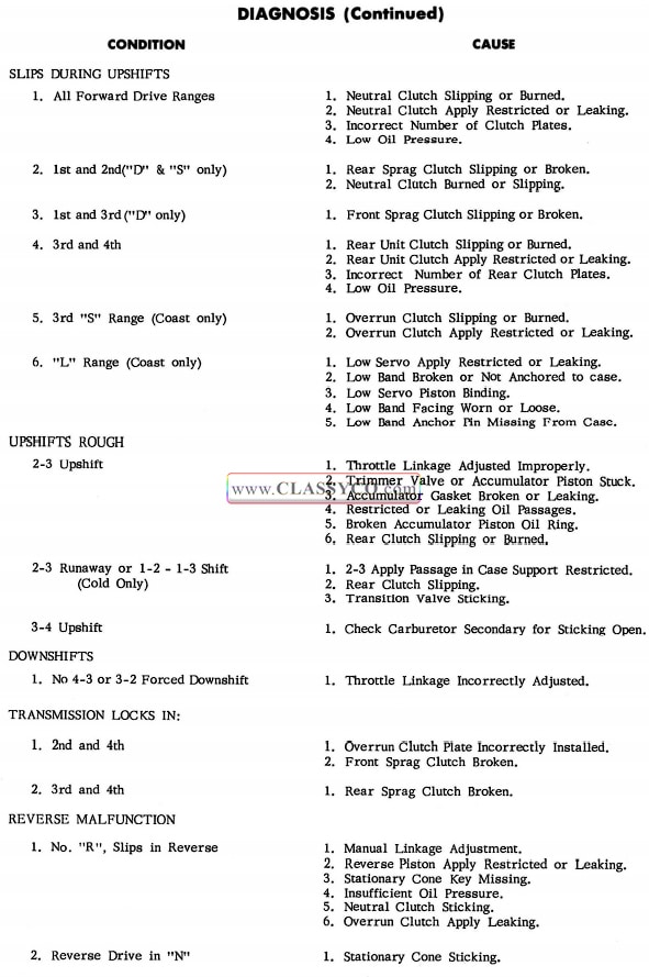
1957 Oldsmobile Hydra-Matic Diagnosis 2
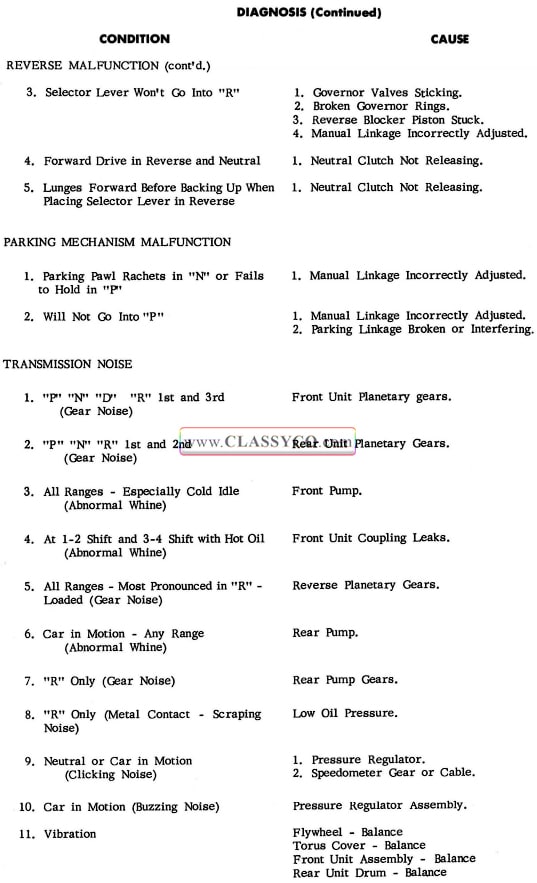
1957 Oldsmobile Hydra-Matic Diagnosis 3
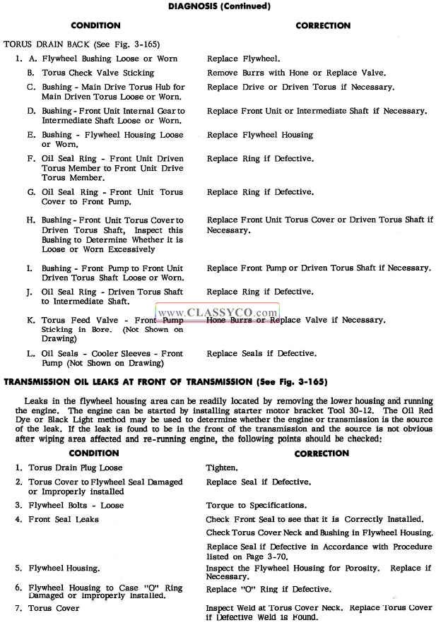
1957 Oldsmobile Hydra-Matic Diagnosis 4
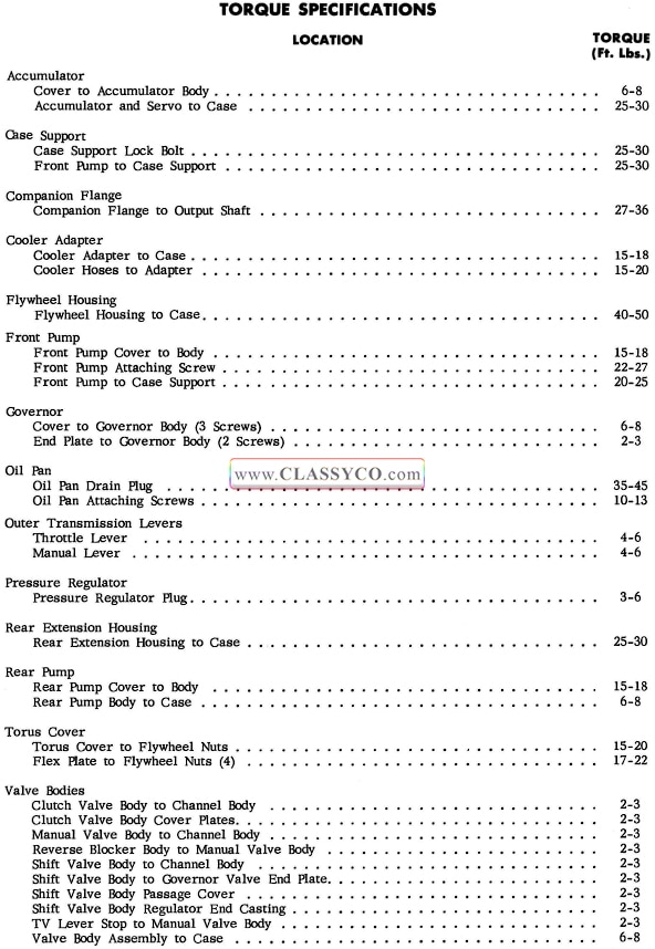
1957 Oldsmobile Hydra-Matic Torque Specifications