STEERING
STEERING LINKAGE (Fig. 5-1)
Improperly adjusted or worn steering linkage can cause excessive play, kickback, front wheel shimmy, car wander, road shock, or poor return of the steering wheel to the straight ahead position. If adjustments do not correct any of the above conditions, the steering linkage should be checked for wear and worn parts should be replaced.
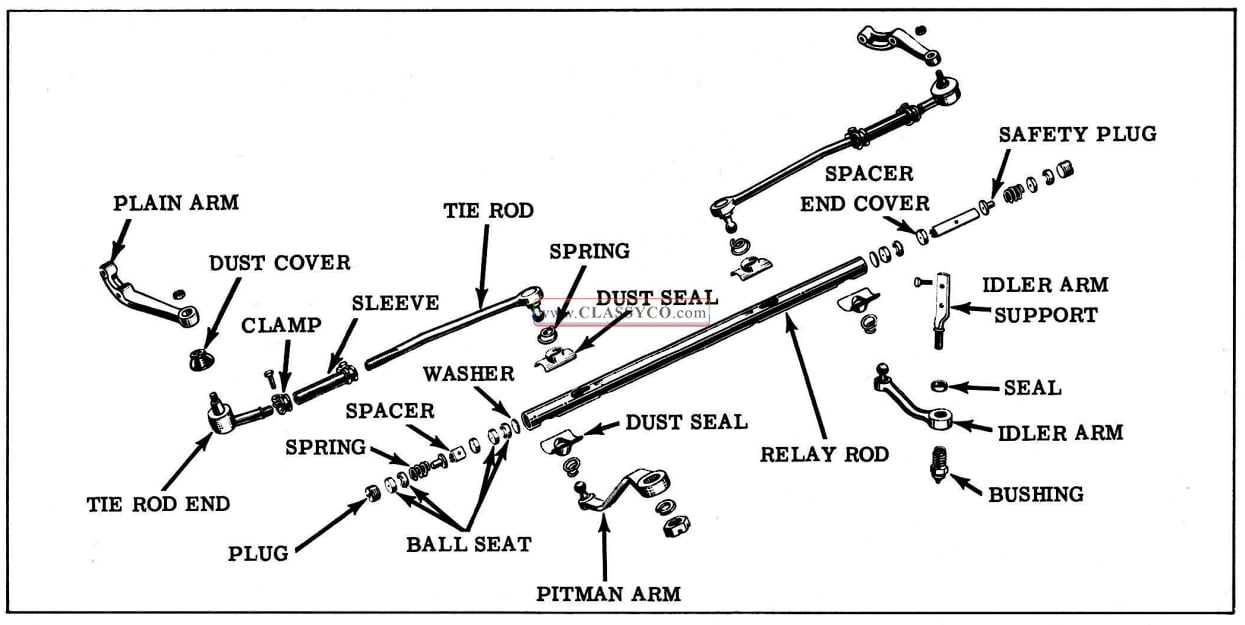
1957 Oldsmobile Steering Linkage
RELAY ROD
To assemble the relay rod, refer to Fig. 5-2.
Install end plugs and adjust by fully tightening and then loosening 1/4 to 3/4 turn. Lubricate relay rod with chassis lubricant. Check toe-in and adjust if necessary.
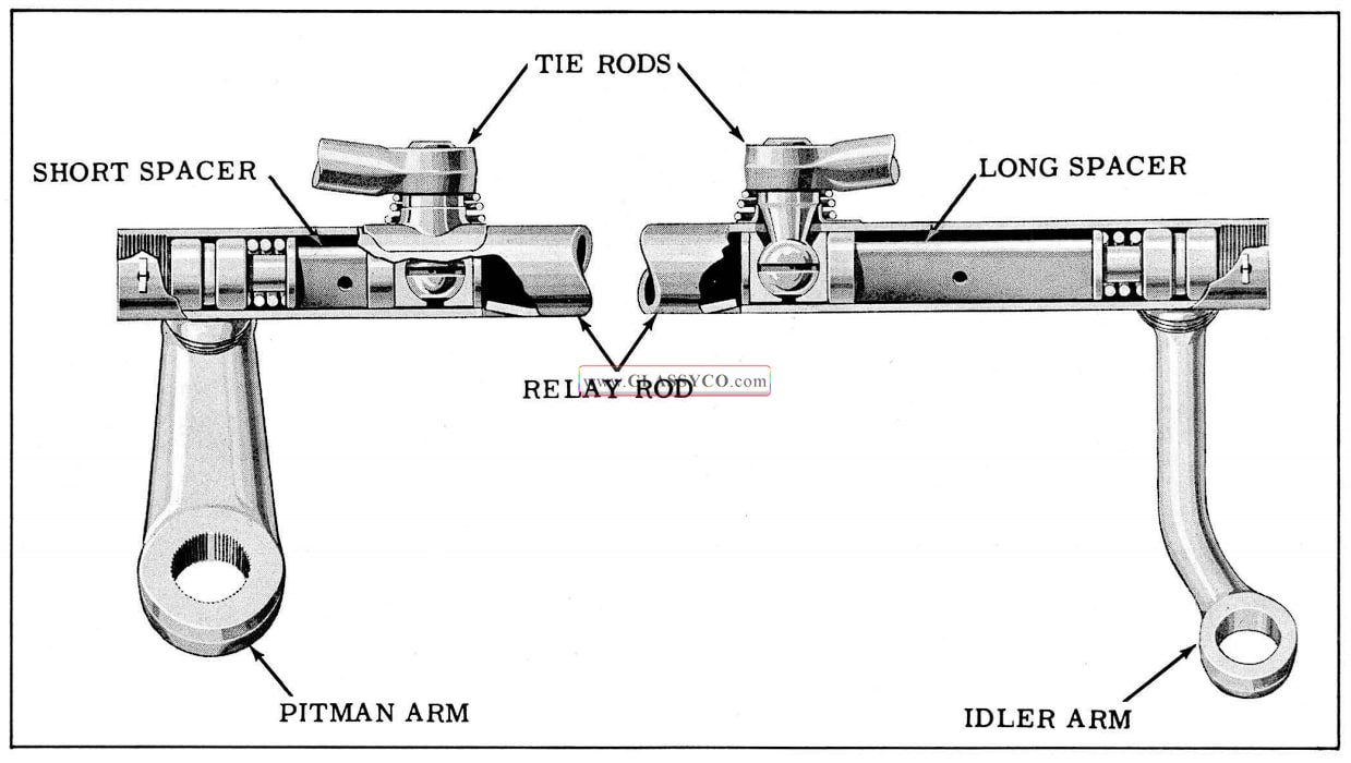
1957 Oldsmobile Relay Rod Assembly
PITMAN ARM
To disconnect the pitman arm from the pitman shaft use Tool J-5504-B or a similar puller. To disconnect the pitman arm from the relay rod, the left end of the steering relay rod must be dis assembled. (See RELAY ROD)
When installing the pitman arm, be sure that the steering wheel and front wheels are in the straight ahead position, then install the pitman arm so that the wide splines of the arm engage the wide spline spaces of the pitman shaft. Torque pitman arm nut 90 to 120 ft. lbs.
IDLER ARM AND SUPPORT
To remove the idler arm and support, remove the idler arm to frame attaching bolts and disassemble the right end of the steering relay rod. (See RELAY ROD)
Whenever the idler arm is disassembled from the idler arm support it must be reassembled so that there is a dimension of 23/32″ between upper face of the idler arm and the shoulder on the sup port as shown in Fig. 5-3. This adjustment must be made with the support removed from the frame as follows:
a. Install idler arm bushing into idler arm and tighten to 100 ft. lbs. (minimum).
b. Turn idler arm support with seal into bushing until the distance between the upper face of the arm and shoulder on support is 23/32″ as shown in Fig. 5-3.
1957 Oldsmobile Idler Arm and Support Clearance
When mounting the idler arm and support to the frame, torque the support to frame attaching bolts 25 to 35ft. lbs.
TIE ROD
To disconnect the outer end of a tie rod, remove the tie rod to plain arm attaching nut, then tap the END of the plain arm with a hammer to free the tie rod from the plain arm. To disconnect the inner end, one end of the relay rod must be dis assembled. (See RELAY ROD)
When installing, torque the tie rod to plain arm attaching nut 40 to 50 ft. lbs. Adjust toe-in, then position inner sleeve clamps as shown in Fig. 5-4. Tighten clamp bolts 20 to 25 ft. lbs.
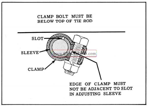
1957 Oldsmobile Inner Sleeve Clamp Positioning
MANUAL STEERING
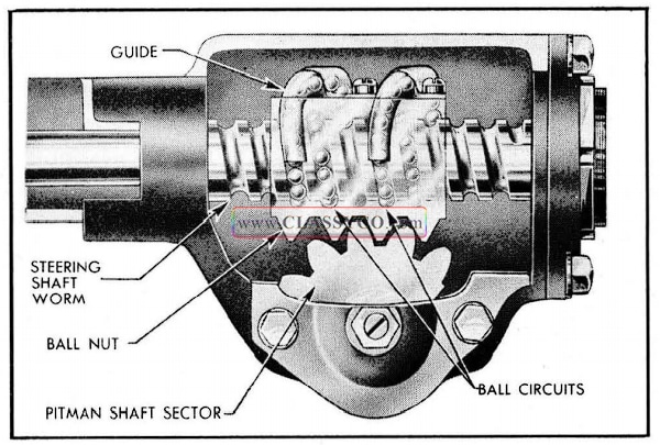
GENERAL DESCRIPTION (Fig. 5-5)
The steering gear is the recirculating ball nut type. The nut, mounted on the worm, is driven through steel balls which circulate in helical grooves in both the worm and nut. Return guides attached to the nut serve to recirculate the two sets of thirty balls through the grooves.
The teeth on the sector, which is forged integral with the pitman shaft, are so designed that a “high point” or tighter fit exists between the ball nut and sector teeth when the front wheels are straight ahead. Proper engagement between the sector and ball nut may be obtained by adjusting the pitman shaft endwise which causes the slightly tapered sector teeth to properly engage the mating teeth on the ball nut.
Adjustment is accomplished by means of a screw which extends through the gear housing side cover. The head of the adjusting screw and a selectively fitted shim fit snugly into a T-slot in the end of the pitman shaft so that end play of the shaft is also controlled by the screw which is locked by an external lock nut. The adjusting screw in the end cover controls the worm shaft bearing pre-load.
1957 Oldsmobile Manual Steering Gear
ADJUSTMENTS
Before any adjustments are made to the steering gear in an attempt to correct such conditions as shimmy, hard or loose steering, or road shock, careful check should be made to determine that front end alignment, shock absorbers, wheel balance, and tire pressure are correct.
There are two adjustments on the recirculating ball nut type steering gear:
- WORM BEARING ADJUSTMENT
- OVER-CENTER ADJUSTMENT
CAUTION: It is important that the worm bearing adjustment be checked and corrected if necessary before the over-center adjustment is made. Failure to follow the proper sequence may result in damage to the steering gear.
Worm Bearing Adjustment
- Disconnect the pitman arm from pitman shaft using Tool J -5504 -B or a similar puller.
- Loosen pitman shaft adjusting screw lock nut and loosen adjusting screw a few turns.
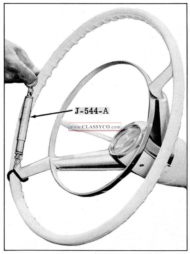
- With spring scale Tool J -544-A at the rim of the steering wheel, measure the pull which is required to keep the wheel in motion at about 30° off straight ahead position. (See Fig. 5-6)
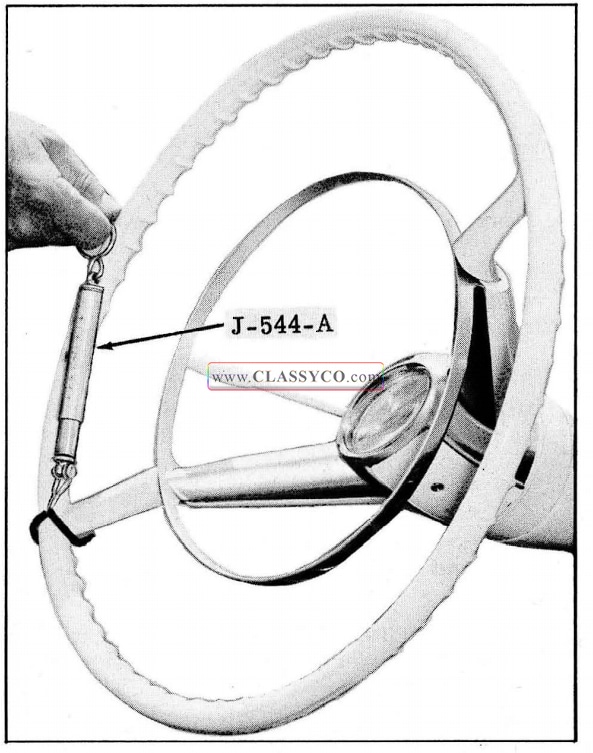
1957 Oldsmobile Checking Worm Bearing Adjustment
- The pull required should be between 1/2 and 7/8 pounds. If it is not, it will be necessary to loosen lock nut at end of worm shaft with Tool J -4388 and turn worn bearing adjusting screw the required amount with Tool KM0-695 to bring the spring pull within limits. (See Fig. 5-7).
- When adjustment is correct, retighten lock nut and recheck preload.
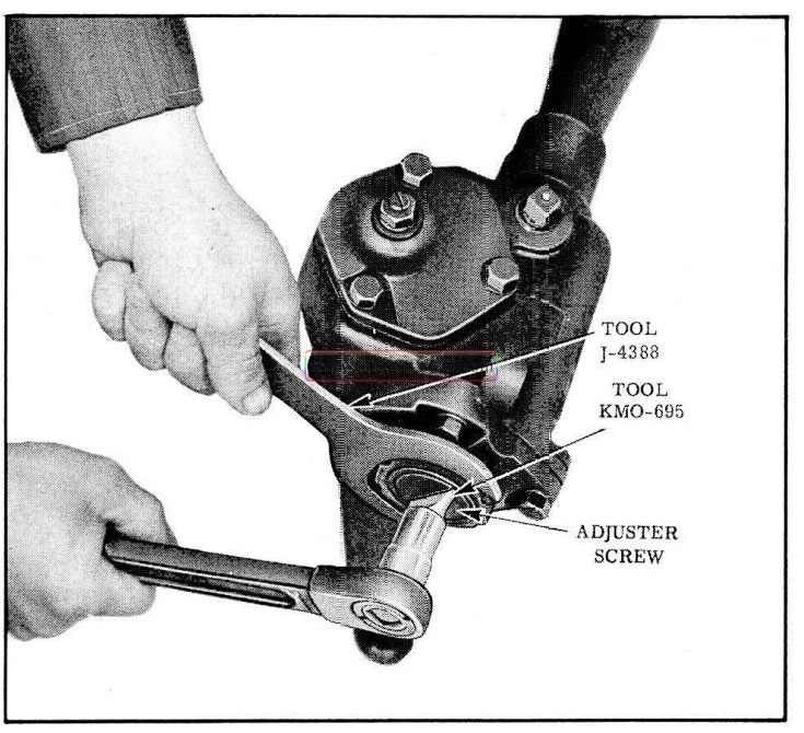
1957 Oldsmobile Adjusting Worm Bearing
Over-Center Adjustment
- The worm bearing adjustment having been made, the pitman shaft adjusting screw should be tightened until a pull of 1-1/2 to 2 pounds at the steering wheel rim is required to turn the wheel through the center range. (See Fig. 5-8) Tighten lock nut.
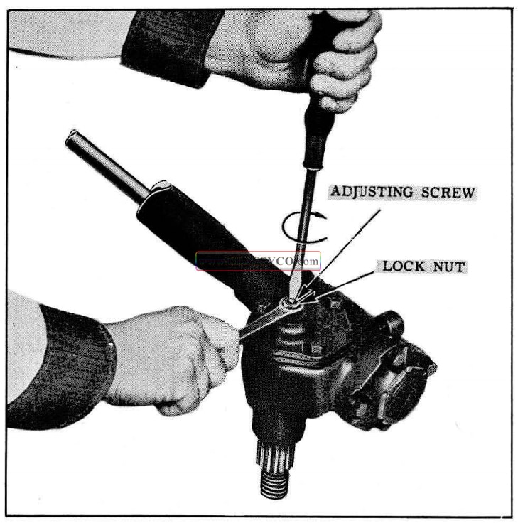
1957 Oldsmobile Over Center Adjustment
- After adjustments have been made, assemble pitman arm to pitman shaft with front wheels and steering wheel in the straight ahead position so that splines will align properly. Torque pitman shaft nut 90 to 120 ft. lbs.
GEAR ASSEMBLY REMOVE AND REPLACE
- Remove steering wheel assembly, upper bearing spring and seat.
- Turn back floor mat and remove mast jacket cover plate attaching screws.
- Remove upper mast jacket clamps. Disconnect shift linkage from lower end of mast jacket.
- Remove the pitman shaft nut, then using Tool J -5504 -B or a similar puller, disengage the pitman arm from the pitman shaft.
- Remove steering gear to frame mounting bolts.
- Remove gear and mast jacket assembly by pulling it up through the opening in the floor. Loosen lower clamp and remove mast jacket from gear. To replace, reverse the above procedure.
IMPORTANT: Tighten upper mast jacket clamp before tightening steering gear to frame bolts. Torque steering gear to frame bolts SO to 60 ft. lbs. Torque pitman shaft nut 90 to 120 ft. lbs.
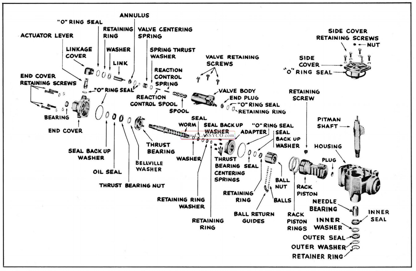
STEERING GEAR DISASSEMBLE (Fig. 5-9)
- Remove steering gear assembly from car and mount on holding fixture J-5205.
- Rotate worm until nut is in center of travel, then remove side cover and pitman shaft from steering gear housing.
- Loosen lock nut and back off adjusting screw from end of worm shaft.
- Remove cover from lower end of worm shaft.
- Remove worm shaft assembly, with ball nut assembly, out through bottom of housing then remove bearings.
- Remove ball return guide clamps and guides from ball nut. Turn ball nut over and remove balls, then remove ball nut from steering shaft worm.
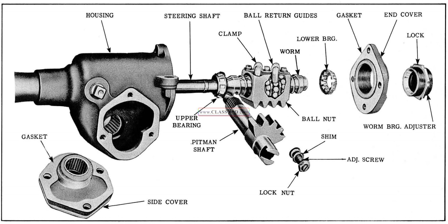
1957 Oldsmobile Steering Gear Nomenclature
Side Cover Needle Bearing
Remove and Replace
NOTE: The 1955 power steering gear end casting bearing puller Tool J-5190, should be con verted to J-5190-A for use on the manual steering gear by replacing the expander jaws (contained in Replacement Kit J-5190-7) and regrinding the taper on the screw as shown in Fig. 5-10.
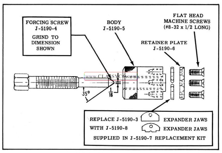
1957 Oldsmobile Tool J-5190-A
- Remove the pitman shaft and adjusting screw from the side cover.
- Loosen the forcing screw of Tool J-5190-A so the expander jaws can be fully retracted.
- Place Tool J-5190-A through needle bearing in side cover.
- Thread a 7/16″ x 20 bolt in the adjusting screw hole in the side cover until Tool J -5190 -A is raised up just enough for the knurled section to clear the bearing.
- Turn the forcing screw in to expand jaws and remove the bearing. (See Fig. 5-11)
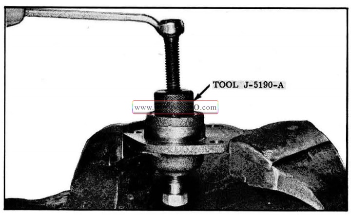
1957 Oldsmobile Removing Side Cover Bearing
To install bearing, use Tool J -5255 and install the bearing flush with surface of the casting bore. (See Fig. 5-12)
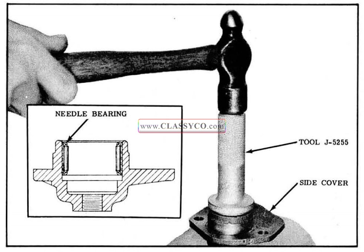
1957 Oldsmobile Installing Side Cover Bearing
IMPORTANT: One end of the needle bearing is stamped with the manufacturer’s identification; always place the stamped end of the bearing against the shoulder of the installing tool so that the unstamped end of the bearing enters the casting first.
Pitman Shaft Needle Bearing and Seal
Remove and Replace
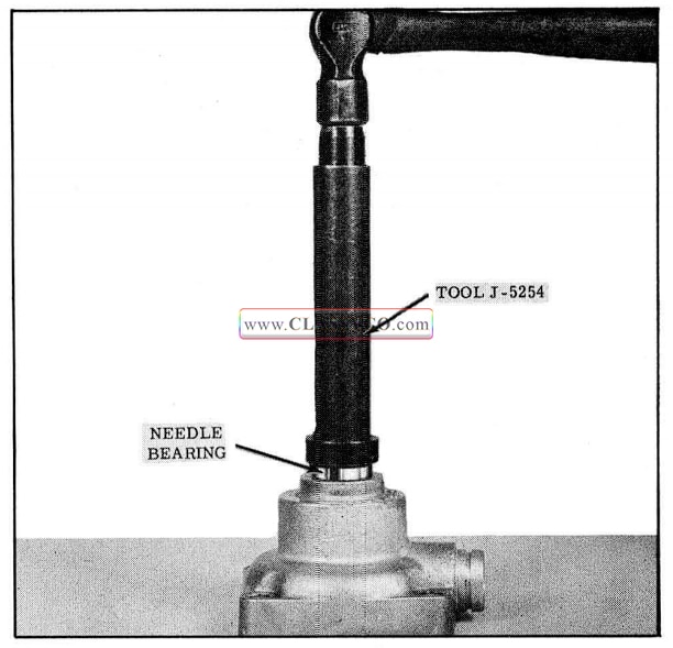
- Use Tool J -5254 to drive bearing and sea l from housing as shown in Fig. 5-13.
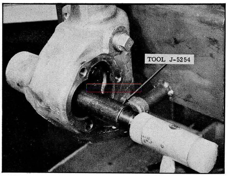
1957 Oldsmobile Removing Bearing From Housing
- Place stamped end of new bearing (manufacturer’s name) against the shoulder of large end of Tool J -5254.
- Install needle bearing in housing so that it is flush with shoulder in counterbore as shown in Fig. 5-14.
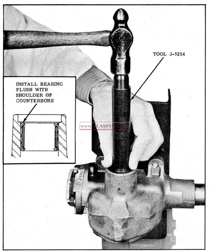
1957 Oldsmobile Installing Bearing in Housing
- Install a new seal into housing with lip of seal facing inward. Drive seal flush with casting, using Tool J -5255. (See Fig. 5-15)
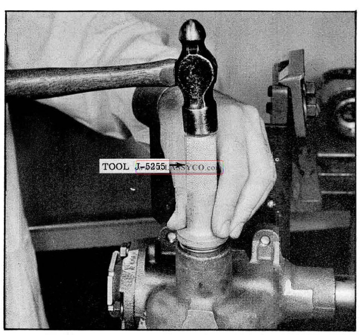
1957 Oldsmobile Installing Pitman Shaft Seal
Pitman Shaft Seal Removal
When removing the seal without removing the pitman shaft bearing, it will be necessary to use a small chisel to collapse the seal so it can be lifted from the housing. (See Fig. 5-16)
Replace seal as in step 4 above.
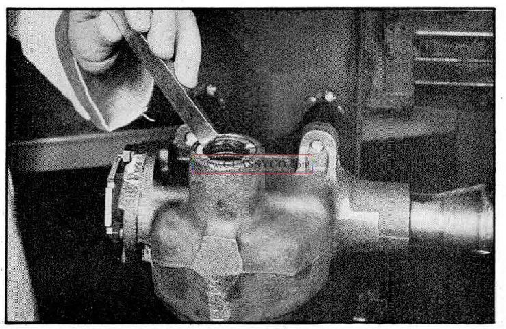
1957 Oldsmobile Removing Pitman Shaft Seal
STEERING GEAR ASSEMBLE
- Before assembling the steering gear, wash all parts in clean solvent and inspect balls, bearings, races, worm, and ball nut for any rough spots or defects.
- Assemble ball nut on worm, making sure that there are 30 balls in each circu1t, making a total of 60 balls. Install return guide clamps.
- Assemble upper and lower bearings or worm shaft and replace worm and shaft in housing. (See Fig. 5-9)
- Attach end cover to lower end of housing, holding worm and bearings in place.
NOTE: Adjuster screw should be adjusted just tight enough at this time to hold the bearing races in place. Final adjustment will be made later.
- Install pitman shaft adjusting screw with lock nut to side cover, then assemble pitman shaft to adjusting screw and back screw out about 3/4″.
NOTE: Particular care must be exercised to assure that teeth on pitman shaft do not bind with teeth on ball nut during installation.
- Install pitman shaft and side cover assembly. After cover is tightened in place, tighten pitman shaft adjusting screw enough so that teeth on shaft and ball nut engage at the middle of worm travel but do not bind. Final adjustment will be made later.
- Fill steering gear with steering gear lubricant.
- Steering gear should be bench adjusted before it is assembled in car as follows:
- Place steering wheel on shaft.
- Turn steering gear from one extreme to the other to make certain there are no unusual binds.
NOTE: Never allow ball nut to strike the ends of the ball races when reaching its extreme position due to the possibility of damaging ball guides.
- Adjust steering gear as outlined under:
- WORM BEARING ADJUSTMENT
- OVER-CENTER ADJUSTMENT
- Remove steering wheel from shaft. Assemble steering gear in car and reinstall steering wheel.
- When mark on steering wheel hub and steering shaft are lined up, wheel spokes should be horizontal as car is driven straight ahead.
If this is not the case, it will be necessary to adjust the tie rod ends until steering wheel assumes its proper position. When a new steering gear is installed, it may be necessary to adjust steering wheel spoke alignment even though spoke alignment had been correct for the old gear.
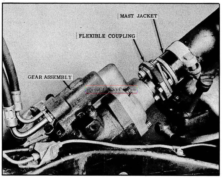
POWER STEERING
The power steering gear assembly employes a flexible coupling which connects the gear assembly to the mast jacket assembly. (See Fig. 5-17) The flexible coupling permits self alignment of the assembly and cushions road shock. This part also permits slight up and down movement of the worm shaft assembly for valve actuation. It also allows the gear assembly or the mast jacket assembly to be removed from the car independently of each other.
1957 Oldsmobile Power Steering Layout
All internal parts of the gear are lubricated with oil supplied by the pump.
The steering gear satisfies two conditions which are: neutral (for straight ahead driving), and power assist (for turning). When effort is not being applied at the steering wheel, the worm shaft and spool valve automatically center themselves resulting in a neutral condition with all passages open so that only a low neutralizing oil pressure exists. Therefore, no power assist is obtained in neutral position. Power assist is regulated by the spool valve which directs oil pressure to either end of the rack-piston. The spool valve is actuated by the “in” or “out” movement of the worm shaft in varying degrees dependent upon the amount of effort applied at the steering wheel.
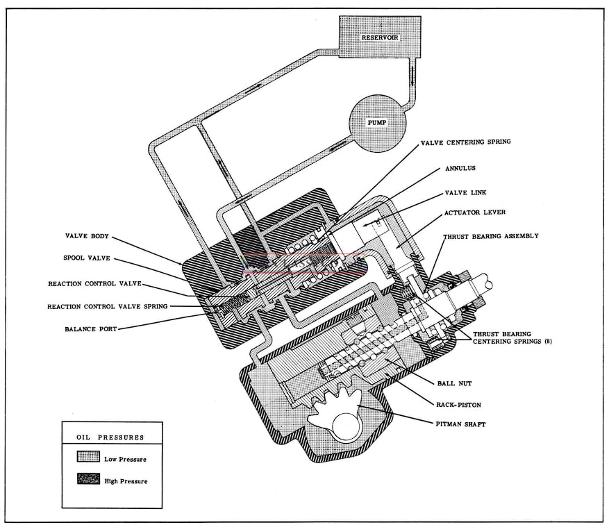
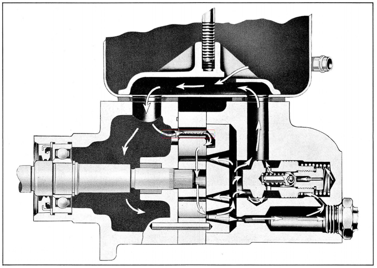
Neutral (Straight Ahead Position) (Fig. 5-18)
There are four centering springs attached to the thrust bearing and four centering springs located between the adapter and the thrust bearing. The opposing forces from these two sets of springs center the worm shaft in a neutral position. When this condition exists, the thrust bearing holds the actuating lever at the center of its travel. In order for the valve assembly to move in either direction, it has to overcome the resistance of the large centering spring on the valve assembly. There fore, since the actuating lever is being held by the thrust bearing, the valve is held in its neutral position by its centering spring. The reaction control valve, located inside the spool valve, is held in its open position by the reaction control spring.
With the valves in neutral position, oil pressure is directed from the pump to the valve body. Since all passages are open, oil is premitted to return to the pump. Oil is also directed to either end of the rack-piston; however, since oil is being re turned to the pump, the oil in the housing is maintained at a very low pressure (approximately 30 to 50 p.s.i.) which furnishes resistance to road shock. In addition, this oil lubricates all com ponents of the gear.
1957 Oldsmobile Neutral Position
POWER ASSIST (For Turning)
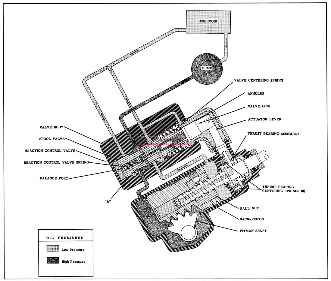
Right Turn (Fig. 5-19)
When the steering wheel is turned to the right, the worm shaft threads into the ball nut. Due to the resistance of the front wheels through the sector to the rack-piston, the rack-piston tends to remain stationary. Due to the resistance of turning between the front wheels of the car and the roadbed, the steering worm tends to screw down into the ball nut; therefore, as the driver applies right-turn effort to the steering wheel, the worm is allowed to move downward an imperceptible amount. As the worm moves downward it also moves the thrust bearing downward, which in turn causes the valve actuating lever to move the spool valve upward. While the valve assembly moves upward, the valve centering spring is compressed against the annulus (held by the snap ring).
With the valve in this position, pump pressure is directed by the spool valve to the lower end of the rack-piston to assist in turning. As the rack piston moves upward, oil on the upper end of the rack-piston is displaced past the spool valve and returns to the pump reservoir. When oil pressure is applied to the lower end of the rack-piston, the reaction control valve remains momentarily in its neutral position. Thus, oil pressure is directed through the reaction control valve and into the reaction chamber. As the oil pressure increases in the reaction chamber, it assists the valve centering spring in centering the spool valve; there fore, more effort is required at the steering wheel. It is this opposing pressure in the reaction chamber that gives the driver the “feel of the road”. The higher resistance to turning, the more the valve assembly is moved upward and the higher the oil pressure on the rack-piston becomes. Since the amount of valve actuation and consequently the amount of hydraulic pressure in the cylinder is dependent upon the resistance to turning, the driver is assured of the proper amount of hydraulic assistance at all times, limited only by the capacity of the pump.
The pressure in the reaction chamber is limited to 250 p.s.i. by the reaction control valve. As the pressure in the reaction chamber builds up, the reaction control valve is forced downward against the reaction control spring and blocks off the passage at (A) Fig. 5-19. With the reaction pressure limited to 250 p.s.i., approximately 4 pounds effort on the steering wheel is required to turn the car in even the most difficult turning conditions.
1957 Oldsmobile Right Turn Position
The balance port (Fig. 5-19) relieves pressure or vacuum at the lower end of the spool valve and reaction valve as it is open to the low pressure line at all times. The thrust bearing and the valve actuating lever are lubricated by the valve body low pressure return passage. Since this passage is open at all times, oil is permitted to enter and return as necessary, dependent upon movement of the worm shaft and valve assembly.
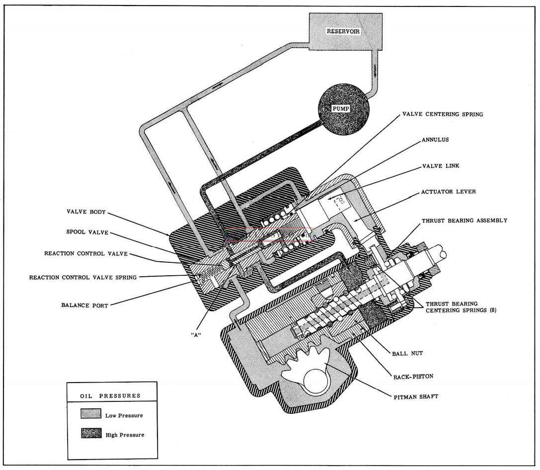
Left Turn (Fig. 5-20)
As effort is applied to the steering wheel for a left turn, the worm shaft will move upward be cause the rack-piston tends to remain stationary due to the resistance of the steering mechanism. As the worm shaft assembly moves upward, over coming the tension of the centering springs mounted on the thrust bearing, the actuating lever moves the spool valve downward. The collar on the spool valve moves the annulus downward compressing the valve centering spring. With the spool valve in this position, pump pressure is directed to the upper end of the rack-piston to assist in turning. Oil on the lower end of the rack-piston is free to return to the pump.
For a left turn, the valves function the same as for a right turn except for the following:
In the right turn position, the annulus is held stationary by a snap ring. The valve centering spring tends to center the spool valve by applying a force on the thrust washer. In the left turn position, the thrust washer is held stationary and the centering spring tries to center the spool valve by forcing the annulus upward.
1957 Oldsmobile Left Turn Position
When oil pressure is directed to the upper end of the rack-piston for a left turn, the oil pressure in this chamber is confined by the oil seal in the adapter, the rack-piston oil rings, and the oil seal on the end of the worm. To prevent a pressure or a vacuum in the chamber below the worm oil seal in the rack-piston, this chamber is vented by a passage inside the worm which extends into the end cover chamber.
MINOR SERVICE OPERATIONS
OIL RECOMMENDATIONS
The recommended oil for use in the hydraulic steering gear system is the Hydra-Matic Transmission Fluid or TYPE “A”. In an emergency, the system can be servied with a good grade of SAE 10 or 10W oil.
The oil level should be checked regularly and maintained at the full mark.
PUMP BELT ADJUSTMENT
Checking
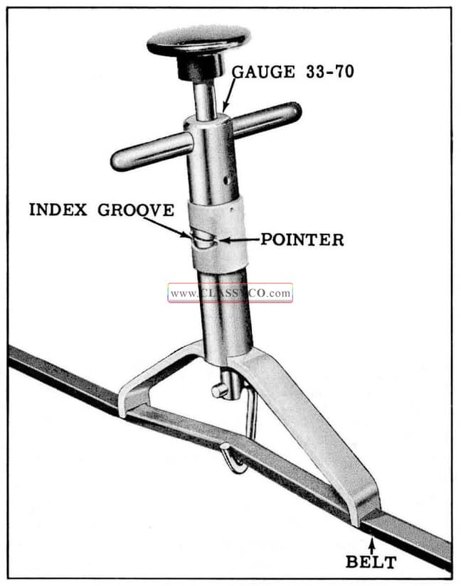
The pump belt adjustment can be checked with out disturbing the pump. To check, position Gauge 33-70 on pump belt as shown in Fig. 5-21. The pointers on sleeve of tool should index with groove in tool plunger. If this condition does not exist, the belt should be adjusted as outlined below.
1957 Oldsmobile Checking Pump Belt Adjustment
Adjustment
- Loosen clamp to pump attaching cap screws.
- With Gauge 33-70 positioned on pump belt as shown in Fig. 5-21, move pump away from engine until pointers on Gauge 33-70 index with groove in gauge plunger. (See Fig. 5-22) Tighten clamp to pump attaching screws.
- Check adjustment and readjust if necessary.
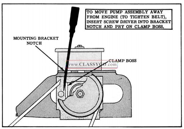
1957 Oldsmobile Adjusting Pump Belt
POWER STEERING GEAR ADJUSTMENT
(On Car)
The over-center adjustment is the only adjustment to be made on the car. However, in order to make this adjustment it is also necessary to check the ball nut and thrust bearing preload.
- Remove pitman shaft nut then disconnect the pitman arm from the pitman shaft using Tool J-5504 -B or a similar puller.
- Loosen pitman shaft adjusting screw lock nut and thread adjusting screw out to limit of its travel.
- Using spring scale J-544-A, check and record the combined ball nut and bearing preload with gear on center (2-1/4 turns from either end of steering wheel travel) and not moving spoke of steering wheel more than in a 6″ arc. (See Fig. 5-23)
1957 Oldsmobile Checking Over Center Preload
NOTE: If this reading is less than 1/4 lbs. or more than 1-1/4 lbs., the ball nut and/or thrust bearing preloads are incorrect. It will be necessary to remove and disassemble the steering gear for the necessary adjustments or replacement of parts.
- With gear on center, adjust pit man shaft adjusting screw so that over-center preload is 1/2 to 3/4 lb. in excess of the worm bearing and ball nut preload that was recorded. Check as shown in Fig. 5-23. Total over-center pre load must not, however, exceed 1-3/4 lbs.
- When the correct over-center preload is obtained, tighten lock nut while holding adjusting screw and recheck preload.
OIL PRESSURE TEST
- Disconnect the pressure line at oil pump, attach Gauge 1-5176 to pump and connect the hose to end of gauge where the valve is located. (See Fig. 5-24)
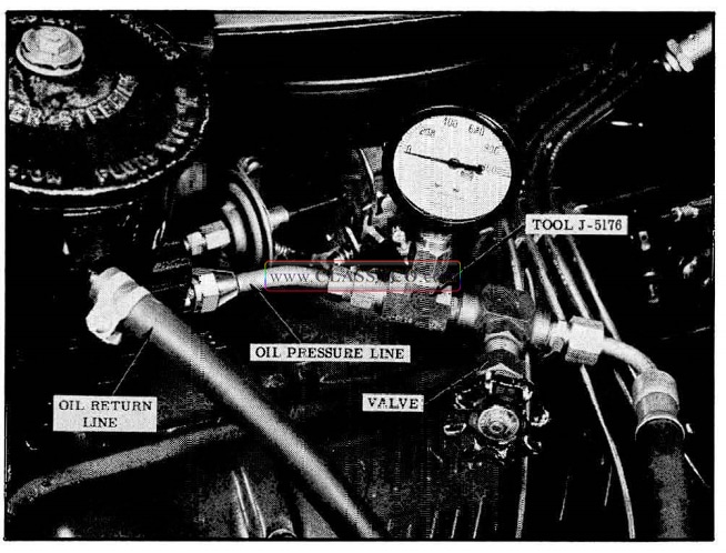
1957 Oldsmobile Checking Oil Pressure
- With gauge valve open, transmission in Park or Neutral position, and engine running at slow idle, turn steering wheel through normal operating range several rimes to allow oil to reach 150° to 170° {measured with a thermo meter in the reservoir).
Note maximum pressures on gauge while holding the steering wheel. momentarily in right and left position.
CAUTION: Do not hold wheel in extreme position for an extended period of time because it will drastically increase the oil temperature and cause undue wear in the oil pump.
- If the maximum oil pressure is less than 800 p.s.i., it indicates trouble in the pump, oil hoses, steering gear, or a combination of these parts. To eliminate the hoses and gear, close the gauge valve and quickly test pressure of the pump with the engine at slow idle; then open the valve to avoid increasing oil temperature.
- Comparing the maximum pressures obtained in these two tests will indicate the source of trouble as follows:
a. First test (step 2) pressure low, and second test (step 3) pressure normal indicates faulty external oil lines or steering gear.
b. First test (step 2) and second test (step 3) pressures equally low, indicates faulty oil pump. If above test shows trouble to be in pump, correct pump as necessary. If trouble is shown to be in steering gear or hoses, examine for external oil leaks and refer to DIAGNOSIS of steering gear.
POWER STEERING GEAR
REMOVAL AND REPLACEMENT
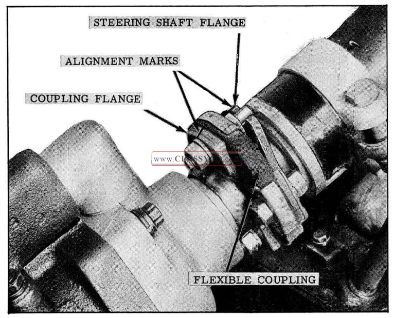
- Scribe alignment marks on the coupling flange and the steering shaft flange. (See Fig. 5-25)
- Disconnect hoses from power steering pump and cap the pump and hose fittings.
- Hoist car and remove engine filler plate.
- Remove pitman shaft nut, then disconnect the pitman arm from the pitman shaft using Tool J-5504-B or a similar puller.
- Remove the 2 flexible coupling to coupling flange attaching nuts and lock washers.
- Remove the 3 gear assembly to frame bolts, then remove gear assembly (with hoses attached) from the car.
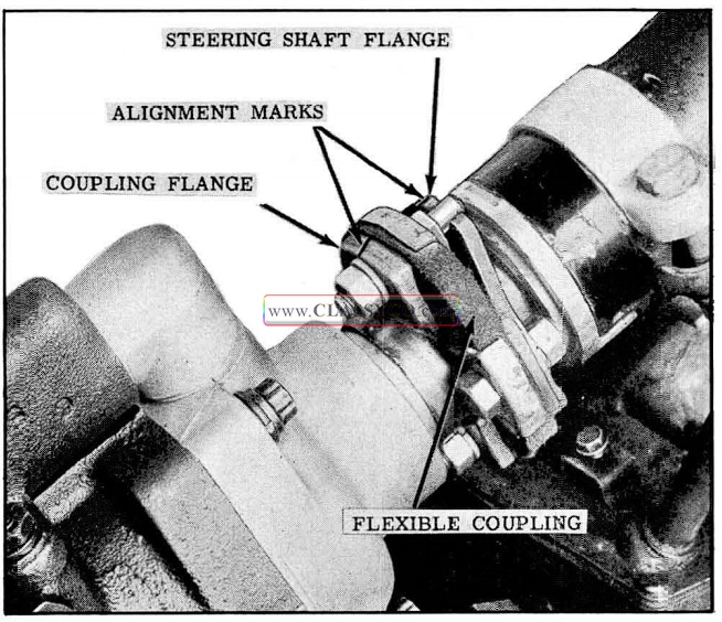
1957 Oldsmobile Alignment Marks
When installing the gear assembly, align the coupling flange and the steering shaft flange alignment marks so that steering wheel will be positioned properly. Make sure that gear housing alignment pin enters hole in frame before tightening mounting bolts. The frame to gear assembly bolts should be torqued 50 to 60 ft. lbs. and the pitman arm nut 90 to 120 ft. lbs.
After the gear assembly is installed and hoses connected to the pump, add Hydra-Matic fluid to the reservoir to bring the fluid level to the full mark. With engine running, turn the steering wheel through its full travel 2 or 3 times to allow air in the system to escape. Recheck oil level and add fluid if necessary.
GENERAL SERVICE PRECAUTIONS
- Disassembly and reassembly of the unit and the sub-assemblies must be made on a clean work bench. As in repairing any hydraulically operated unit, cleanliness is of the utmost importance; therefore, the bench, tools, and parts must be kept clean at all times.
- Extreme caution must be exercised during assembly of the unit in the manner in which the oil seals are handled. All seal protecting tools or devices must be used when assembling the units with splined parts. The slightest flaw in the sealing surface can cause an oil leak.
- The aluminum castings and the control valve parts are very susceptible to nicks, burrs, etc., and care should be exercised while handling them.
- The internal snap rings must be expanded if they are to be reused. This will insure proper seating when installed.
- Install new “O” rings when servicing a unit.
- Sealing compound should not be used on seals in this unit.
- During assembly of the unit, all internal parts must be lubricated with Hydra -Matic oil.
- Before disassembly, thoroughly clean the exterior of the unit.
DISASSEMBLY OF GEAR (Fig. 5-26)
1957 Oldsmobile Power Steering Gear
- Mark alignment of coupling flange and worm shaft.
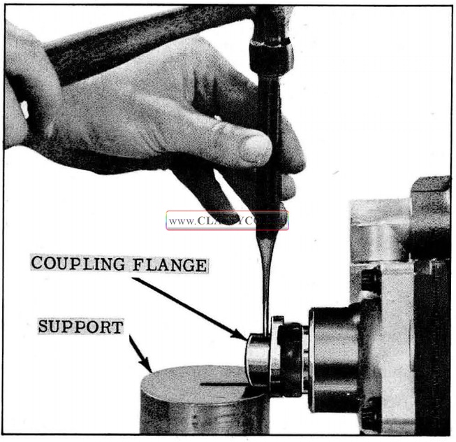
- Drive out coupling flange retaining pin. (See Fig. 5-27)
1957 Oldsmobile Coupling Flange Pin Removal
NOTE: Coupling flange must be supported when driving out the pin to prevent damage to the end cover bearing.
- Mount gear assembly on modified Holding Fixture J -5205, then mount holding fixture and gear assembly on Differential Holding Fixture J-3289-B. (See Fig. 5-28)
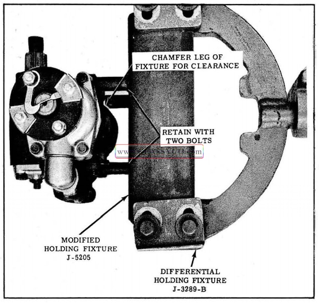
1957 Oldsmobile Holding Fixture
- With the valve body facing down, remove plugs from the hydraulic hoses, then turn coupling flange 2 or 3 times through it full travel to drain oil from gear.
- Remove hoses from the valve body.
- Turn fixture so that valve body faces up and remove 3 valve body cap screws, then remove the valve body and linkage cover by pulling straight out from the housing. (See Fig. 5-29)
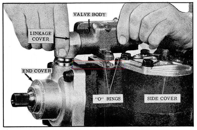
1957 Oldsmobile Removing Valve Body
- Remove the 2 valve body to housing “O” rings from the housing.
- Loosen the pitman shaft adjusting screw lock nut.
- Remove the 5 side cover cap screws and rotate the cover 1/2 turn.
- Align pitman shaft gear with opening in housing. (See Fig. 5-30)
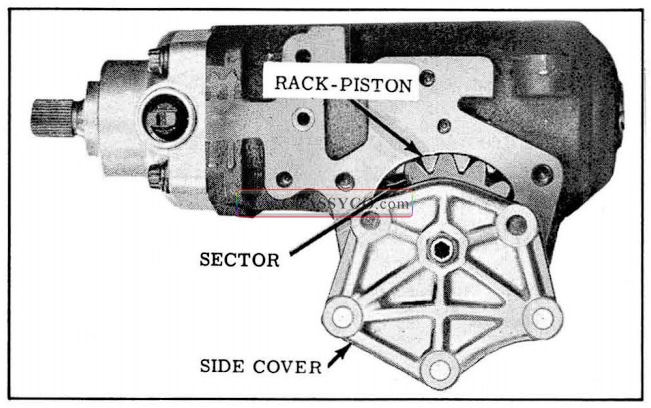
1957 Oldsmobile Aligning Pitman Shaft for Removal
- Tap the pitman shaft with a plastic hammer and pull the pitman shaft out of the housing.
- Pull the coupling flange and felt wick from the worm shaft.
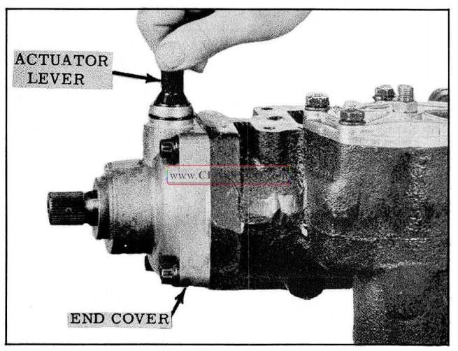
- Pull actuator lever from the end cover. (See Fig. 5-31)
1957 Oldsmobile Actuator Lever Removal
- Remove the 4 end cover attaching screws (use a 12 point socket), then pull end cover from the housing.
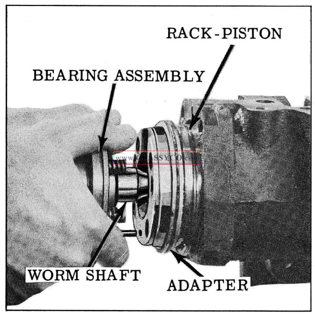
- Pull out on the worm shaft until centering springs are exposed, then remove the 4 centering springs from the adapter. (See Fig. 5-32)
1957 Oldsmobile Rack-Piston Removal
- Pull the rack-piston and worm assembly from the housing.
SERVICING INDIVIDUAL UNITS
CONTROL VALVE ASSEMBLY
Disassembly (Fig. 5-33)
1957 Oldsmobile Valve Assembly
- Pull linkage cover from the valve body and remove “O” ring.
- Remove the larger snap ring with internal pliers and pull the valve assembly and washer from the valve body.
- Remove the washer and “O” ring from the valve assembly.
- Remove valve body plug snap ring with in ternal pliers; then, using a wood dowel, push plug from end of valve body. (See Fig. 5-34)
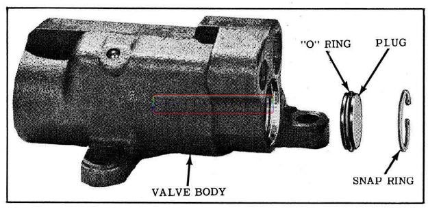
1957 Oldsmobile Valve Body Plug
- If disassembly of valve assembly is necessary:
a. Clamp end of spool valve in Tool J-6293; then, using Tool J-6224 remove the valve link. (See Fig. 5-35)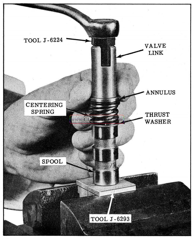
1957 Oldsmobile Removing Valve Link
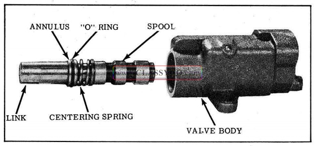
b. Remove the annulus, valve centering spring and thrust washer from the spool valve. (See Fig. 5-36)
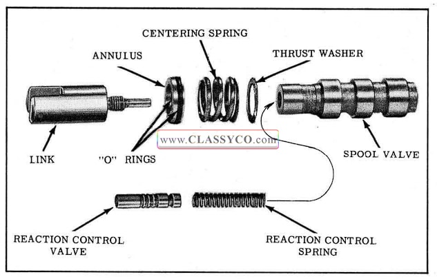
1957 Oldsmobile Valve Assembly Nomenclature
c. Remove the reaction control valve and spring from bore of spool valve.
d. Remove inner “O” ring from annulus. - If hose connections were leaking at connector seats, remove one or both connectors as follows:
a. Thread a nut and place a washer over a 10-24 tap (for the small connector) or a 5/16-18 tap (for the large connector).
b. Coat end of the ta p with petrolatum to prevent chips from entering passage while tapping the connector.
c. With the valve body in a horizontal position, thread the tap into the connector not more than 3 turns.
d. Tighten nut to remove connector as shown in Fig. 5-37.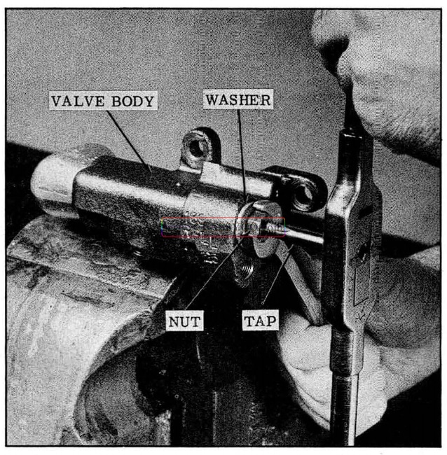
1957 Oldsmobile Removing Connector
Cleaning and Inspection
- Wash all parts in clean solvent, blow out all passages and dry parts with compressed air.
- Check control valve body for scores, chips or other irregularities.
- Control valve must be free to move back and forth in the control valve body. Any minor nicks or scratches may be removed with a fine hone.
Assembly (Fig. 5-36)
- Install new “O” ring on valve body plug, coat “O” ring with Hydra-Matic oil and install plug and snap ring in end. of valve body.
- To reassemble valve assembly:
a. Clamp the end of the spool valve in Tool J-6293. (See Fig. 5-35)
b. Install reaction control spring and reaction control valve (open end out) into the spool valve.
c. Install inner and outer “O” rings on the annulus and coat with Hydra-Matic oil.
d. Install thrust washer (bevel side down), valve centering spring, and annulus (narrow land next to spring) on spool valve.
e. Thread link into spool valve and torque 12 to 15 ft. lbs. using Tool J-6224. - To install new connectors, use Tool J-6217 to seat them in the valve body. (See Fig. 5-38)
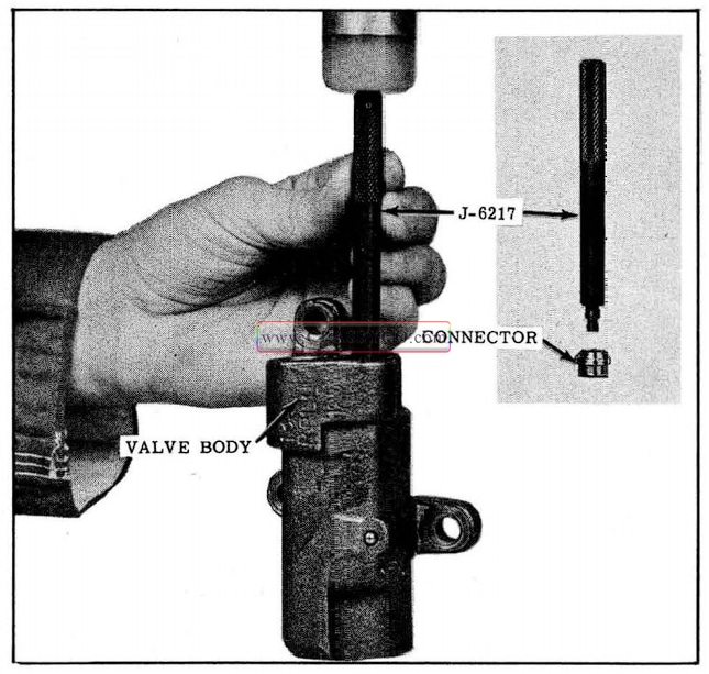
1957 Oldsmobile Installing Connector
- Slide valve assembly into valve body, then place steel washer over link (chamfered side toward valve). (See Fig. 5-39)
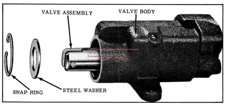
1957 Oldsmobile Installing Valve Assembly
- Install snap ring (chamfered side out) to retain valve assembly.
- Install new “O” ring on linkage cover and coat with Hydra-Matic oil.
- Install the linkage cover and align valve link and linkage cover as shown in Fig. 5-40. Torque attaching cap screws 15-20 ft. lbs.
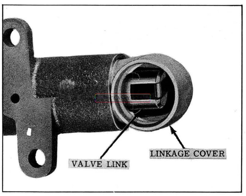
1957 Oldsmobile Valve Cover and Link Alignment
PITMAN SHAFT AND COVER (Fig. 5-41)
Disassembly
- Remove the pitman shaft adjusting screw lock nut and discard.
- Thread adjusting screw through pitman shaft cover, then remove cover.
- Remove “O” ring from cover.
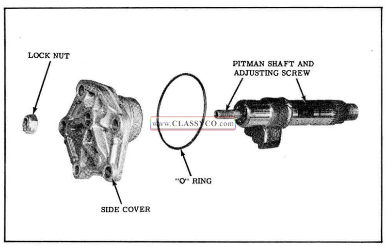
1957 Oldsmobile Pitman Shaft and Side Cover
Cleaning and Inspection
- Wash all parts in clean solvent and dry parts with compressed air.
- Check pitman shaft for scoring or irregularities. Make sure that bearing surfaces of the shaft are not nicked or rough.
- Check sealing surfaces of the pitman shaft. Make sure they are free from roughness, nicks, etc. Minor irregularities in surface can be cleaned up by use of crocus cloth.
- Check teeth on pitman shaft and rack -piston for nicks, burrs, or other irregularities.
Assembly
- In cases where gear chucking or “clunk” cannot be corrected by performing the over-center adjustment (See POWER STEERING GEAR ADJUSTMENT (On Car)), the trouble may be due to excessive clearance of the adjusting screw in the pitman shaft. The clearance MUST be checked as follows:
a. Remove pitman shaft oil seals.
b. Install pitman shaft end side cover to gear housing. Loosen pitman shaft adjusting screw a few turns and tighten lock nut.
c. Install Dial Indicator KMO-30 as shown in Fig. 5-42 and check end play of pitman shaft. Replace pitman shaft and adjusting screw if end play exceeds .002″.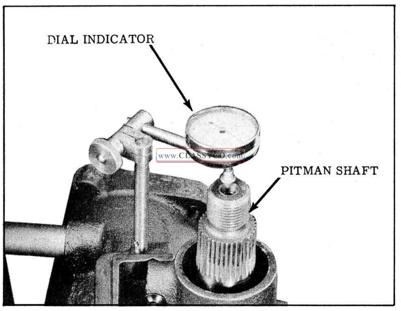
1957 Oldsmobile Checking End Clearance
IMPORTANT: DO NOT ATTEMPT TO correct end play by disassembling pitman shaft.
- Thread the adjusting screw through the side cover until the side cover bottoms on the pitman shaft.
- Install lock nut but do not tighten.
- Install a new “O” ring into recess of side cover and retain with petrolatum.
END COVER
Disassembly
- Remove the 2 “O” rings.
- If necessary to replace needle bearing, drive out needle bearing washer and seal. (See Fig. 5-43)
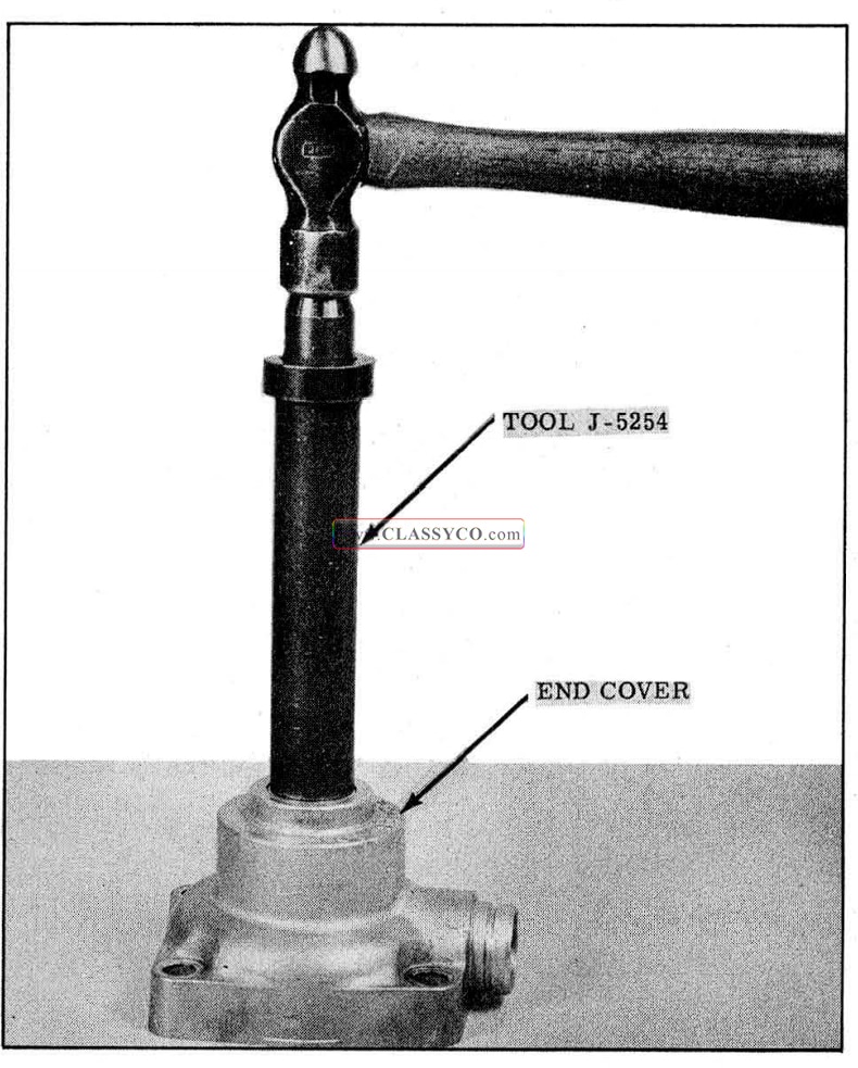
1957 Oldsmobile Needle Bearing Removal
- If bearing removal is not necessary, remove seal and washer as shown in Fig. 5-44.
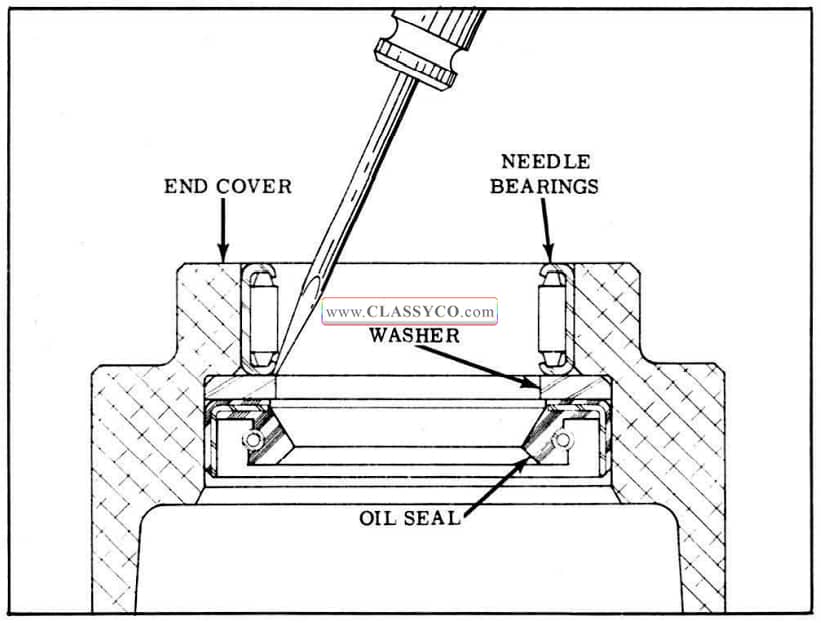
1957 Oldsmobile Seal Removal
Cleaning and Inspection
- Wash all parts in clean solvent, blow out all passages, and dry parts with compressed air.
- All mating surfaces must be free from nicks and burrs. Any irregularities may be removed with crocus cloth.
- Inspect actuating lever bore in end cover for wear. If badly worn, the end cover should be replaced.
Assembly
- If the needle bearing and seal were removed:
a. Install washer in oil seal recess in cover.
b. Place a new seal over the large end of Tool J -5254 with lip facing the shoulder of the tool.
CAUTION: Tool J-5254 must be free of burrs that could scratch the seal.
c. Install seal so that it seats against the washer. (See Fig. 5-45)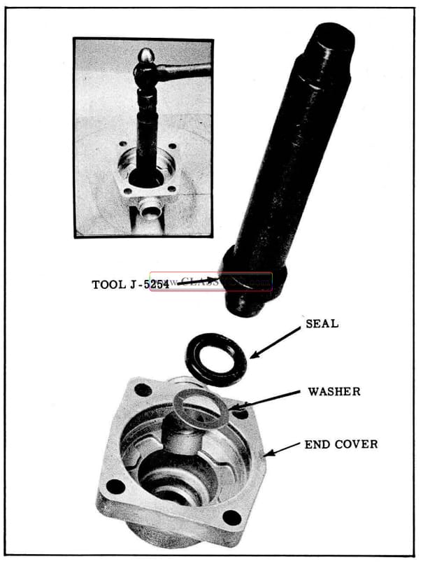
1957 Oldsmobile Installing Seal
NOTE: Support the cover, since the tool will project through the end cover.
d. Coat lip of seal with seal lubricant, Part No. 567196.
e. Place a new needle bearing over the large end of Tool J -5254 with the markings against the shoulder of the tool. (See Fig. 5-46)
1957 Oldsmobile Installing Bearing
f. Drive bearing into end cover until tool bottoms on cover.
g. Make sure needle bearings operate freely.
2. If seal only was removed, refer to steps a, b, c, and d above for installation.
3. Pack needle bearing with high melting point, fine fiber, sodium base grease.
4. Install “O” ring in end cover flange and in “O” ring groove on side of the cover. Coat both “O” rings with Hydra-Matic oil.
HOUSING
Disassembly
- If pitman shaft seals ONLY are to be replaced, remove pitman shaft seals by removing snap ring, outer steel washer, then pry out oil seals and inner washer. (See Fig. 5-47)
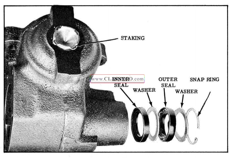
1957 Oldsmobile Pitman Shaft Seals
- If pitman shaft needle bearing replacement is necessary, remove snap ring (use internal pliers) steel washer, then drive needle bearing, seals and inner washer out with Tool J-6278. (See Fig. 5-48)
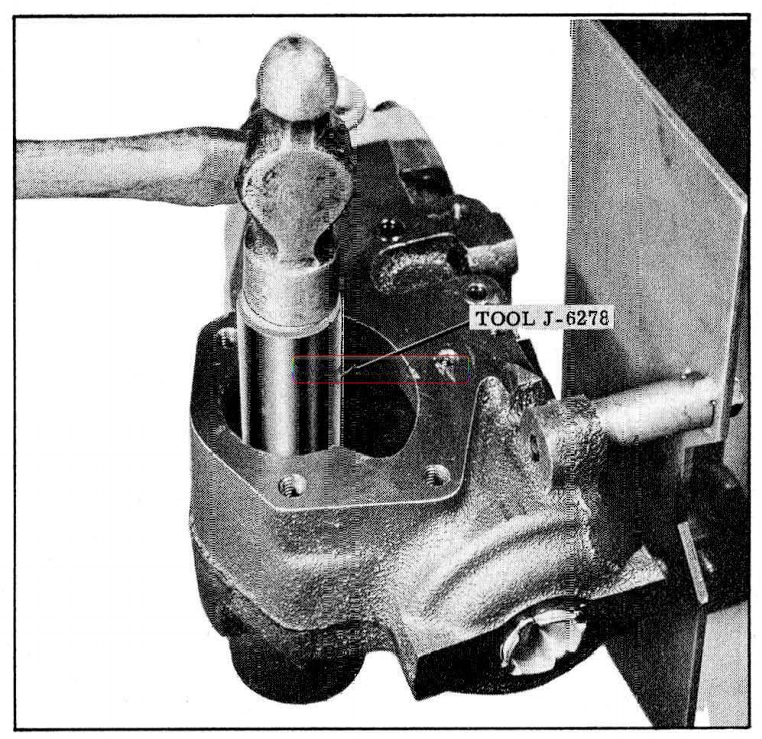
1957 Oldsmobile Needle Bearing and Pitman Shaft Seals Removal
- If the housing plug shows evidence of leakage, remove the staking with a hack saw, remove any burrs that could score the housing, and drive plug into housing.
Cleaning and Inspection
- Wash all parts in clean solvent, blow out all passages, and dry parts with compressed air.
- Check the housing for scores and undue wear.
- All mating surfaces must be free from picks and burrs. Any irregularities may be removed with crocus cloth.
- Check housing cylinder for a shoulder condition at either end of rack-piston travel. If shoulder exists due to excessive wear, housing replacement is necessary.
Assembly
- If pitman shaft needle bearing was removed, place Tool J-6278-2 over Tool J-6278, slide the new needle bearing on the tool with the manufacturer’s identification against the tool and drive needle bearing into housing. (See Fig. 5-49)
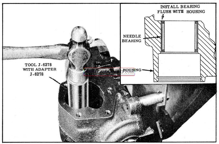
1957 Oldsmobile Installing Needle Bearing
- With adapter 1-6278 over Tool J-6278, install outer seal, inner steel washer, and inner seal on tool with lips of seals facing away from tool, and drive seals into housing.
- Coat the lips of the oil seals with seal lubricant, Part No. 567196.
- Drive the seals in the housing until the top of the adapter Tool J-6278-2 is flush with the steering gear housing. (See Fig. 5-50)
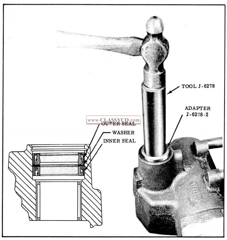
1957 Oldsmobile Installing Oil Seals
- Remove the tool, then install the outer steel washer and internal snap ring. The snap ring will not seat in its groove at this time.
- Reinsert Tool J-6278 with Adapter 1-6278-2 and continue driving until the snap ring seats in its groove.
- If the housing plug was removed, install a new “O” ring coated with Hydra-Matic oil on a new plug, and tap plug into the housing.
- While backing up plug, stake in 4 places 90° apart. (See Fig. 5-47)
RACK-PISTON, WORM SHAFT, AND BALL NUT ASSEMBLY
Disassembly
- Clamp rack-piston assembly in a vise, grind off set screw stake, then remove set screw as shown in Fig. 5-51.
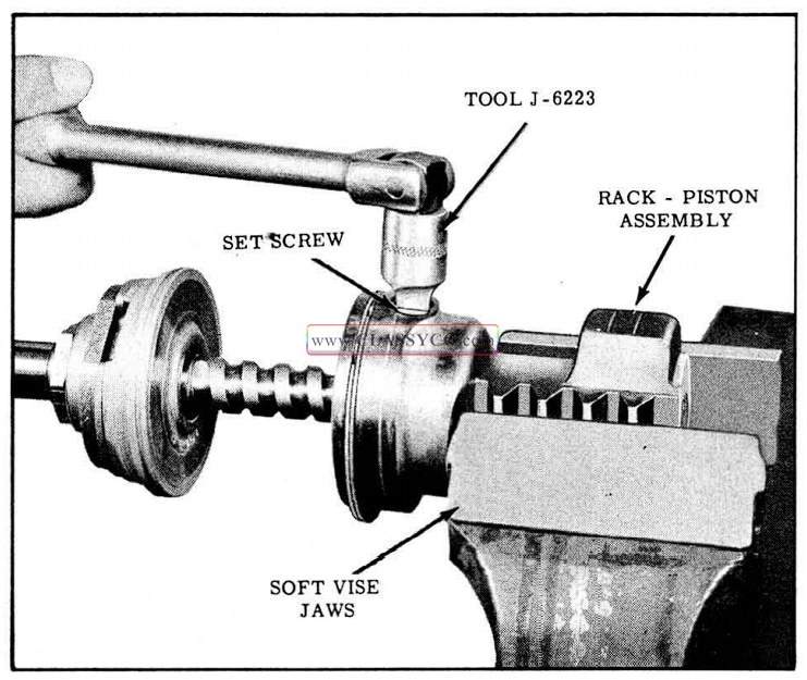
1957 Oldsmobile Removing Set Screw
- Turn ball nut 180° and pull worm shaft and ball nut assembly from rack-piston. Exercise care so that ball guides do not fall out of ball nut.
- Check over-center preload by using Spring Scale J-5178 as follows:
a. Tape the end of a 3ft. length of string onto the ball nut so that the tape also retains the ball guides.
b. Tie the other end of the string to Spring Scale J -5178, then wrap string around ball nut 3 or 4 times.
c. Slowly pull on spring scale and check over center preload. (See Fig. 5-52) Preload should be 1 to 6 lbs.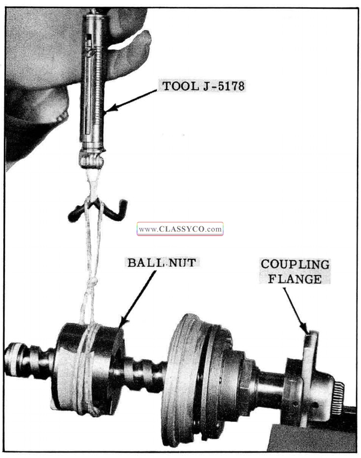
1957 Oldsmobile Checking Over Center Preload (2)
- If over-center preload is not within limits, a new set of balls must be installed upon reassembly. Note the ball size stamped on the end of the ball nut. (If no number is apparent, the ball size is #7.) If over-center preload is incorrect, upon reassembly try a selective set of the next size larger balls if the preload is insufficient or a size smaller if the preload is in excess.
- Remove the ball return guides. Rotate the worm back and forth until all balls have dropped out of the nut.
- Remove the ball nut and adapter from the worm.
- Remove the adapter “O” ring.
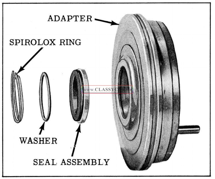
- Remove the Spirolox ring and push the washer and seal assembly from the adapter. (See Fig. 5-53)
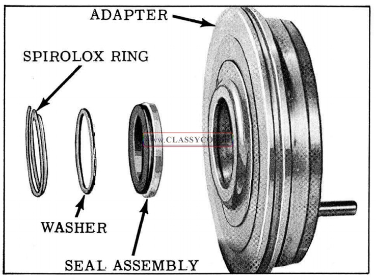
1957 Oldsmobile Adapter Oil Seal
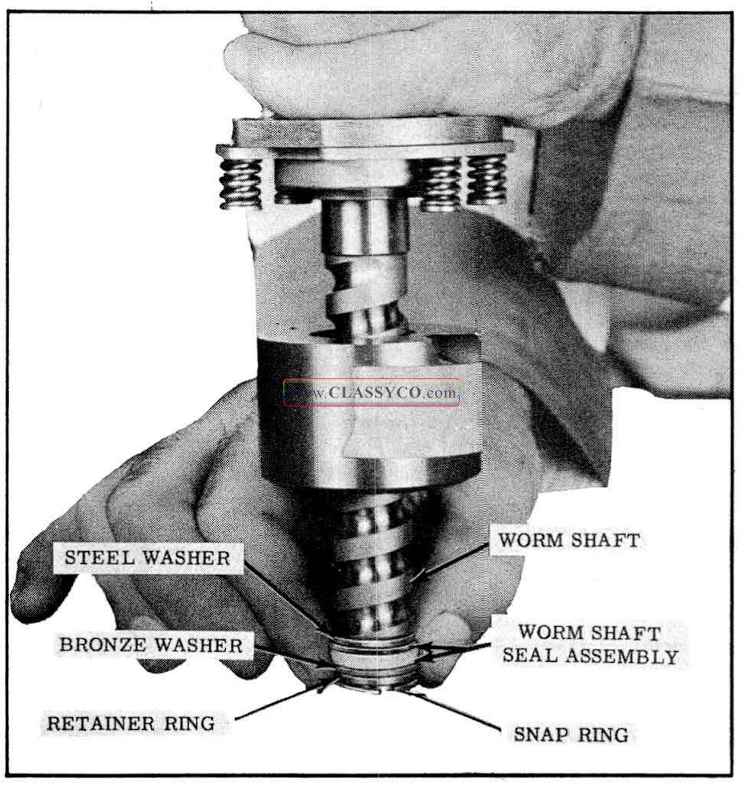
- Cut and remove the worm shaft seal assembly, then remove the snap ring, retaining ring, bronze washer, and steel washer. (See Fig. 5-54)
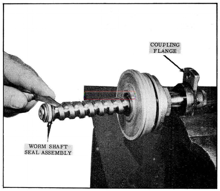
1957 Oldsmobile Worm Shaft Seal Assembly
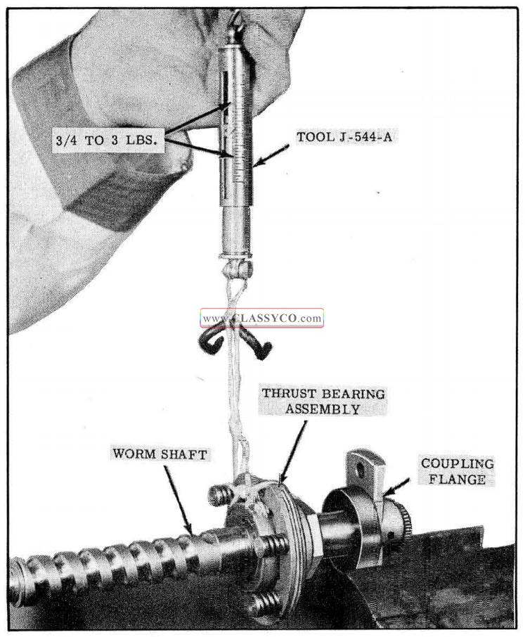
- Check thrust bearing preload by using Spring Scale J -544-A as follows:
- Tie a 3 ft. length of string on a thrust bearing centering spring and to Spring Scale J -544-A. Support the assembly in a vise, wrap string around center race 2 or 3 turns, and check preload as shown in Fig. 5-55. Preload should be 3/4 to 3 lbs.
1957 Oldsmobile Checking Thrust Bearing Preload
NOTE: The above check will indicate one of three conditions:
a. With the preload within tolerance and bearing not rough, further disassembly is not necessary.
b. If the bearing is not rough but the preload is outside of the tolerance, it will be necessary to remove the adjusting nut, install a new one and adjust preload to 1-1/2 lbs. (See Fig. 5-56)
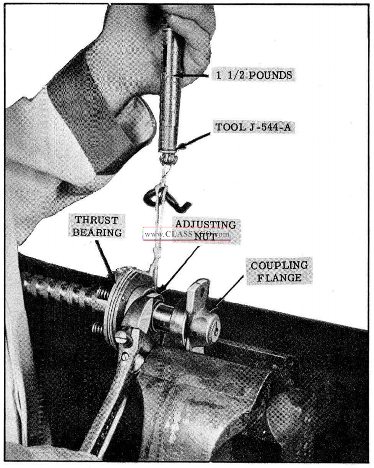
1957 Oldsmobile Adjusting Thrust Bearing
c. If the preload reading is erratic, indicating a rough bearing, it will be necessary to remove the bearing.
13. Remove oil rings from rack-piston if replacement is necessary.
14. Check plug in end of rack-piston. If loose, restake or replace plug. (See Fig. 5-57)
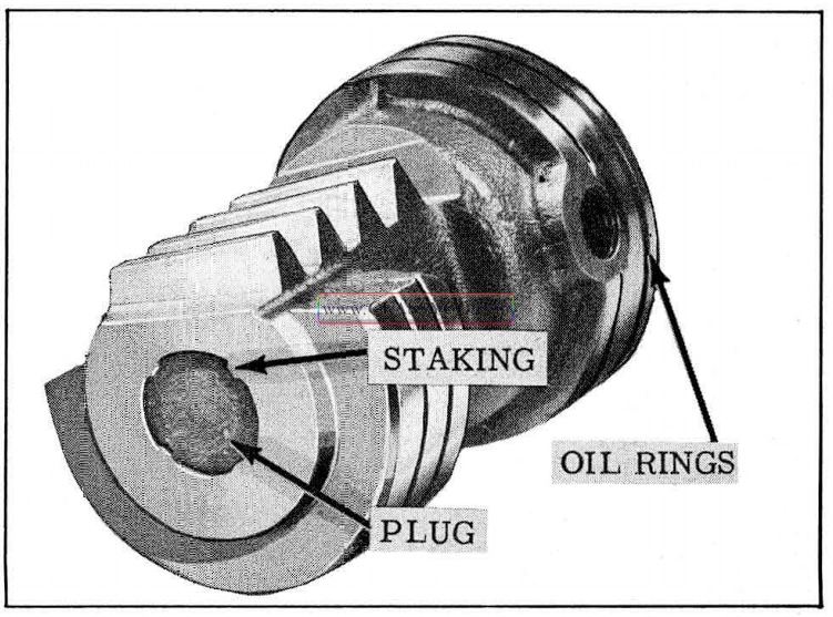
1957 Oldsmobile Rack Piston
Cleaning and Inspection
- Wash all parts in clean solvent, blow out all passages and dry parts with compressed air.
- Check bearing assembly for undue wear or brinelling of the races.
- Check sealing surfaces of worm shaft and pitman shaft. Make sure they are free from roughness, nicks, etc. Minor irregularities in surface can be cleaned by use of crocus cloth.
- All mating surfaces must be free from nicks and burrs. Any irregularities may be removed with crocus cloth.
- Inspect the worm and ball nut grooves and all of the balls for wear or scoring. If either the worm or ball nut need replacing, both must be replaced as a matched assembly.
- Make sure that the ends of the ball return guides are not damaged.
Assembly
- Install oil rings on rack-piston if they were removed.
- If thrust bearing was removed, oil a new bearing assembly and install bearing assembly over worm shaft with springs facing away from splined end of the shaft.
- Install Bellville washer with concave side facing bearing. Install a new nut and adjust pre-load as outlined under Step 10. (See RACK-PISTON, WORM SHAFT AND BALL NUT DISASSEMBLY) Stake nut into keyway of shaft and recheck preload.
- Install new adapter oil seal assembly as shown in Fig. 5-58, then install steel washer and Spirolox ring.
1957 Oldsmobile Adapter Oil Seal (2)
- Install a new “O” ring on adapter, then slide adapter over worm with holes in adapter facing bearing centering springs.
- Slide ball nut over worm with beveled side of ball nut facing the seal end of the worm shaft.
- Install 17 balls into ball nut and lubricate with Hydra-Matic oil.
NOTE: Since the worm shaft is cam ground (thicker at the center), the balls can be installed easier if the ball nut is positioned near one end of the worm.
- Install 6 balls into return guide and retain with petrolatum, then install assembly into ball nut.
- Check ball nut over-center preload if it was necessary to install a new set of balls to correct the over-center preload. After the correct preload is obtained, place masking tape over ball guides to prevent them from falling out.
- Over the end of the worm, install the steel washer, seal assembly (neoprene next to steel washer), bronze washer and retainer ring.
- While holding assembled parts, press worm shaft into snap ring, then force snap ring into groove. (See Fig. 5-59)
1957 Oldsmobile Installing Worm Seal Snap Ring Ring
- Remove tape from ball nut assembly and install worm and ball nut assembly into rackpiston with set screw hole aligned.
- Clamp rack-piston in a vise and install a new set screw as shown in Fig. 5-60. Torque set screw 30-35 ft. lbs. then stake set screw so that rack-piston metal enters both ends of screw slot.
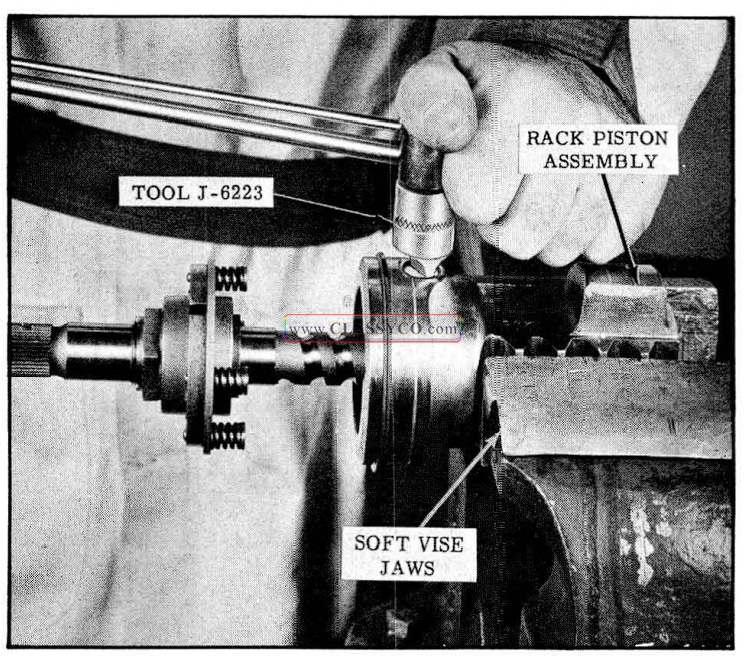
1957 Oldsmobile Torquing Set Screw
ASSEMBLY OF GEAR
- Thread worm out of ball nut as far as possible and coat oil rings and adapter “O” ring with Hydra -Matic oil.
- Turn the housing so that the valve body side is facing up, then place Ring Compressor Tool J-6216 in recess of housing. (See Fig. 5-61)
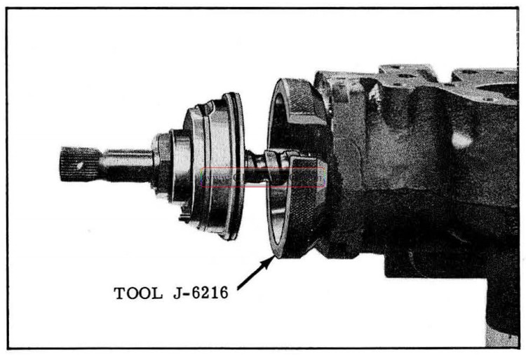
1957 Oldsmobile Installing Rack Piston
- With the rack-piston teeth facing the pitman shaft area, push the rack-piston through the ring compressor so that the oil rings are just inside the housing, then remove ring compressor.
IMPORTANT: Use extreme care when in stalling oil rings. Be sure that gap in Tool J-6216 does not damage oil rings.
- With the notch in the adapter facing the machined side of the housing, push the adapter into the housing recess.
- Install the 4 centering springs into the shallow bores of the adapter. (See Fig. 5-62)
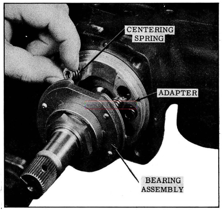
1957 Oldsmobile Installing Centering Springs
- With the dowel hole in the bearing assembly aligned with the adapter dowel, push the bearing assembly tight against the adapter.
- Place Tool J -6222 over splines of worm shaft, then install end cover and torque cap screws 25-30 ft. lbs.; remove Tool J-6222. (See Fig. 5-63)
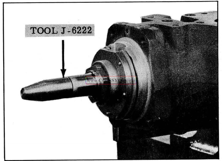
1957 Oldsmobile Seal Protector
- Saturate coupling flange wick with Hydra-Matic oil and place over worm shaft.
- Position coupling flange over worm shaft with alignment marks indexed, but do not install retaining pin.
- Turn coupling flange so that rack-piston teeth are centered in the pitman shaft cover opening in the housing. Make sure that rack-piston teeth are square with center line of pitman shaft bushing. (See Fig. 5-64)
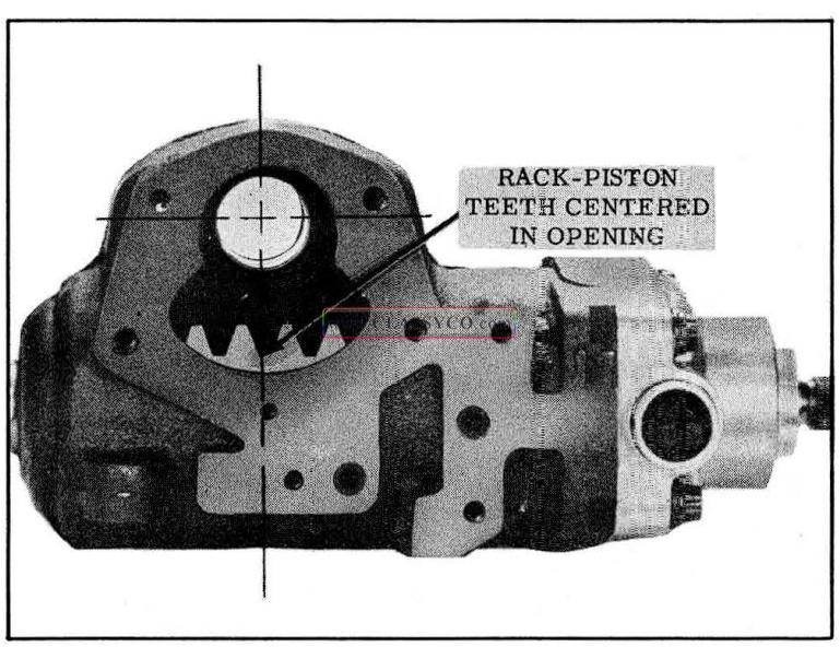
1957 Oldsmobile Centering-Rack Piston Teeth
- Install pitman shaft and side cover assembly. The center tooth of the pitman shaft must engage the center groove of the rack.
- Install the side cover cap screws and torque the four 3/8″ cap screws 25 to 30 ft. lbs. Torque the 5/16″ cap screw 15 to 20 ft. lbs.
- Install actuator lever in end cover and engage lever with the “flat” on the bearing assembly.
- Install the 2 “O” rings in the housing. (See Fig. 5-65)
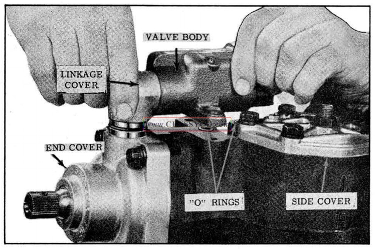
1957 Oldsmobile Installing Valve Body
- With the actuator lever engaged with the valve link pin, install valve body and tighten cap screws finger tight. Turn the worm to extreme left and right position and then center to allow the valve body to centralize, then tighten valve body attaching screws 15 to 20 ft. lbs. in sequence as shown in Fig. 5-66.
1957 Oldsmobile Valve Body Torque Sequence
- Make sure that the pitman shaft adjusting screw is backed all the way out.
- Using Tool J-6281 and Spring Scale J-544-A, check and record the combined ball nut and bearing preload with gear on center (2-1/4 turns from either end of travel) and not moving end of Tool J-6281 more than in a 6″ arc. (See Fig. 5-67)
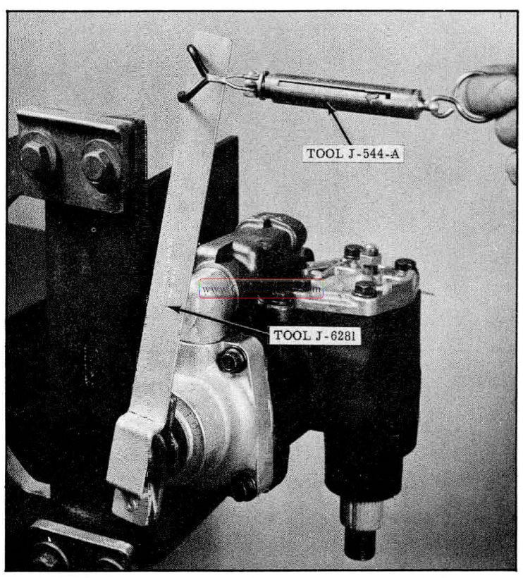
1957 Oldsmobile Checking Ball Nut and Thrust Bearing Preload
- Thread pitman shaft adjusting screw in until pitman shaft gear just touches the rack-piston.
- While checking as in step 17, adjust pitman shaft screw so that 1/2 to 1 lb. in excess of ball nut and bearing preload is obtained.
NOTE: Total over-center preload must be 1-1/4 to I-3/4 lbs.; if not, it will be necessary to check and/or readjust the thrust bearing and/or the worm and ball nut.
- When correct over-center load is obtained, tighten adjusting screw lock nut and recheck over-center preload.
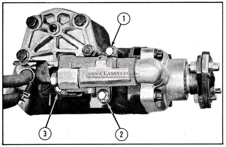
- Install hoses and clip as shown in Fig. 5-68.
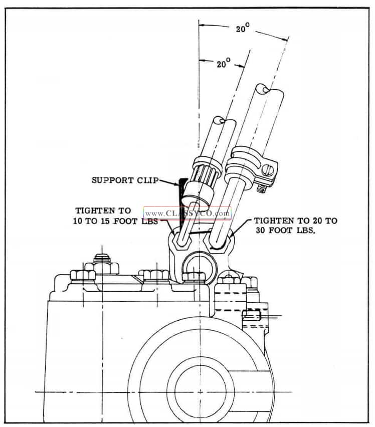
1957 Oldsmobile Hose Installation
- Remove gear assembly from holding fixture and drive in coupling flange pin while supporting the worm shaft and flange. (See Fig. 5-69)
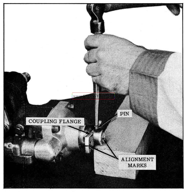
1957 Oldsmobile Installing Coupling Flange Pin
- Make sure that housing alignment pin is extending approximately 11/32″ from the mounting boss. (See Fig. 5-70)
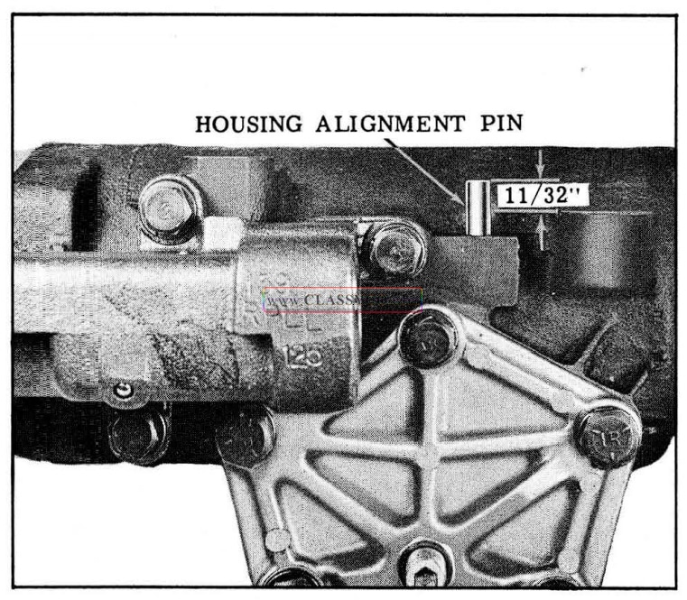
1957 Oldsmobile Housing Alignment Pin
POWER STEERING PUMP
REMOVAL
- Disconnect hoses from pump and cap pump fittings. Secure ends of hoses above fluid level.
- Remove pulley attaching nut.
- Loosen clamp to pump attaching cap screws, then remove belt and pulley.
CAUTION: Do not hammer pulley off shaft as this may damage pump bearing.
- Remove clamp to pump attaching cap screws, then remove pump and clamp.
REPLACEMENT
- Position pump and clamp on bracket and install cap screws finger tight.
- Slide pulley on shaft and install pulley nut finger tight.
- Connect and tighten hose fittings.
- Fill reservoir with Hydra-Matic fluid, then bleed pump by turning pulley counter-clockwise until air bubbles cease to appear. Refill reservoir to proper fluid level if necessary.
- Install pump belt and adjust (See PUMP BELT ADJUSTMENT)
- Tighten pulley nut 35 to 45ft. lbs.
DISASSEMBLY (Fig. 5-71)
1957 Oldsmobile Power Steering Pump
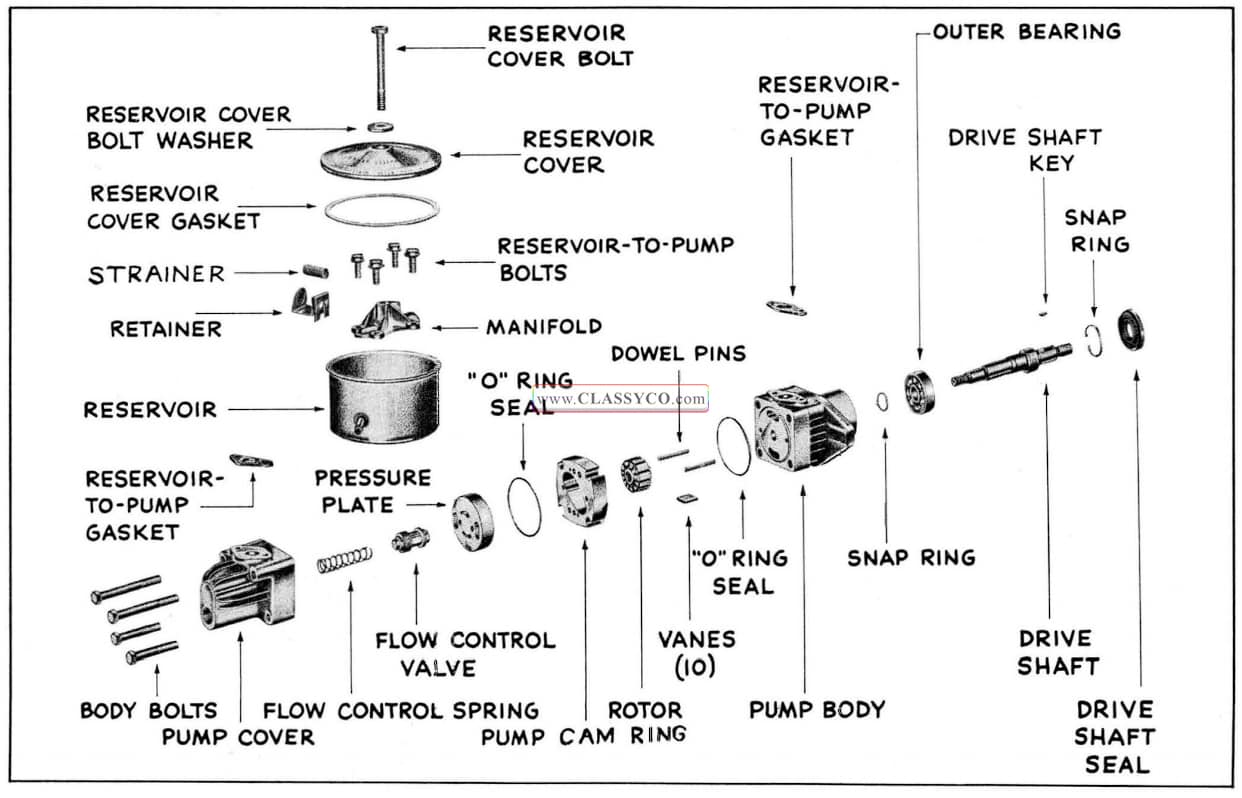
1957 Oldsmobile Power Steering Pump – Nomenclature
With the inlet and outlet fittings capped to pre vent entrance of dirt, thoroughly clean exterior of pump; then remove fitting caps and proceed as follows:
- Remove the reservoir cover and gasket, then drain reservoir.
- Remove the strainer and retainer as an assembly from the return tube.
- Remove 4 cap screws from inside reservoir, then remove reservoir, manifold and the 2 cork gaskets.
- Remove union fitting (with “O” ring) from pump cover.
- Scribe alignment marks on pump body, cam ring and cover. (See Fig. 5-72)
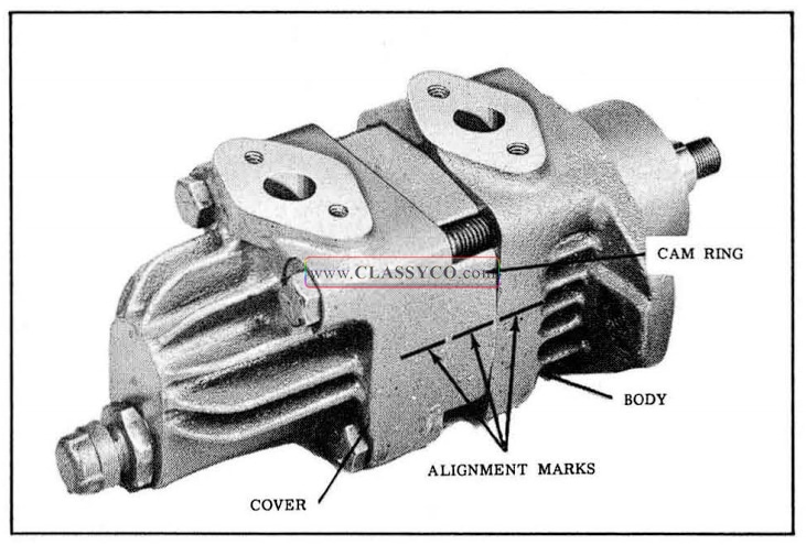
1957 Oldsmobile Alignment Marks (2)
- Insert 1/4″ wooden dowel in reservoir hole of pump cover to retain flow control valve. (See Fig. 5-73)
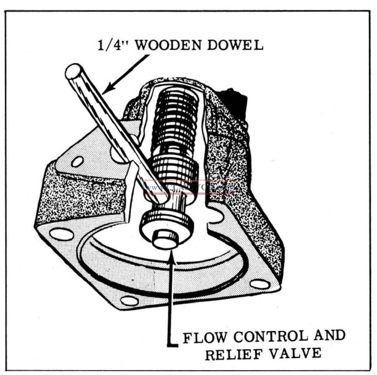
1957 Oldsmobile Retaining Oil Flow Valve
- Remove pump cover to pump body attaching bolts and remove pump cover, “O” ring and flow control valve.
- Remove flow control valve and spring from pump cover.
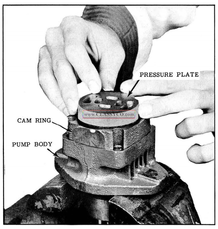
- Remove pressure plate, cam ring, rotor, vanes and “O” ring. (See Fig. 5 74)
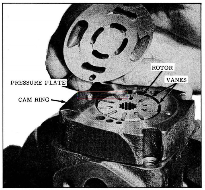
1957 Oldsmobile Pressure Plate Removal
- Punch drive shaft seal with screw driver and pry out seal. (See Fig. 5-75)
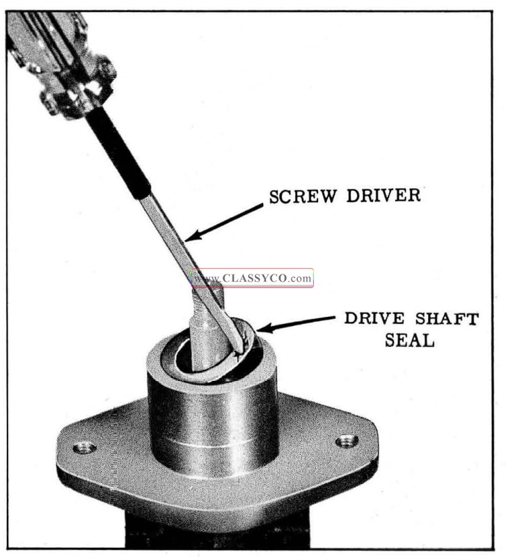
1957 Oldsmobile Oil Seal Removal
- Remove bearing snap ring, then remove drive shaft with bearing from pump body by tapping with a plastic hammer. (See Fig. 5-76)
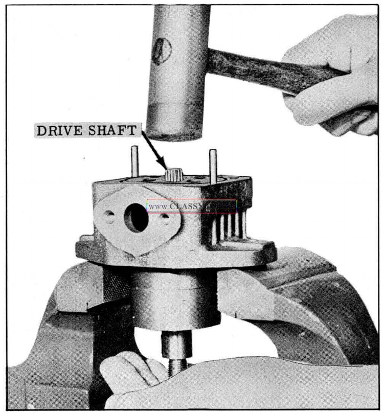
1957 Oldsmobile Drive Shaft and Bearing Removal
- If bearing is to be replaced, remove snap ring from drive shaft and press bearing from shaft.
NOTE: The bushing inside the pump body is not removable. If necessary to replace the body or bushing, they must be replaced as an assembly.
- The flow control and relief valve may be dis assembled for cleaning. When disassembling valve, carefully remove plug to prevent loss of poppet ball or shims. (See Fig. 5-77)
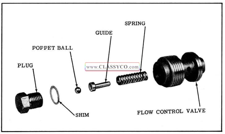
1957 Oldsmobile Flow Control and Relief Valve
CLEANING AND INSPECTION
- Wash parts in clean solvent, blow out all passages with compressed air and air dry.
- Inspect the drive shaft for wear and see that area of shaft on which the seal rides is entirely smooth and free of nicks. Check drive shaft bearing for roughness or noisy operation.
- Check fit of vanes in slots of rotor. Vanes must slide freely but snugly in slots. Tight ness may be relieved by thorough cleaning or removal of irregularities by honing with a fine stone. Replace rotor and/or vanes if excessive looseness exists between rotor and vanes.
- Inspect all ground surfaces of the cam ring for roughness or irregular wear. Slight irregularities may be removed with a fine hone. Replace ring if inside cam surface is scored or worn.
- Inspect the flat faces of the pressure plate and body for wear or scoring. Light scores may be smoothed by light lapping, after which all lapping compound must be thoroughly washed away.
- Inspect ground surfaces of flow control valve. Check freedom of movement of flow control valve within its bore. Slight irregularities may be corrected by honing with a fine stone.
- Inspect all passages in over and body for obstructions or dirt.
ASSEMBLY
In assembling the pump, use new “O” ring seals and gaskets. Make sure all parts are absolutely clean and lubricate all moving parts with clean Hydra-Matic fluid during assembly.
- Assemble flow control and relief valve as shown in Fig. 5-77. Use the same number of shims removed, as altering the shim thickness will change relief pressure. Tighten the plug to approximately 4ft. lbs.
- If bearing was removed, press the new bearing onto the drive shaft by applying pressure on the INNER bearing race. Install snap ring on shaft.
- With shaft supported to prevent damage to bearing, tap key into drive shaft.
- Install shaft and bearing assembly by tapping lightly on OUTER bearing race until bearing bottoms in pump body.
- Install snap ring (with flat side against bearing in pump body).
- Apply seal lubricant, Part No. 567196 to the O.D. and sealing lip of new seal.
- Place oil seal into housing with lip of seal toward the housing. Drive seal into pump body. (See Fig. 5-78)
1957 Oldsmobile Seal and Driving Tool
- Install a new “O” ring, dowel pins (if removed), and rotor with chamfered end of spline facing the pump body. (See Fig. 5-79)
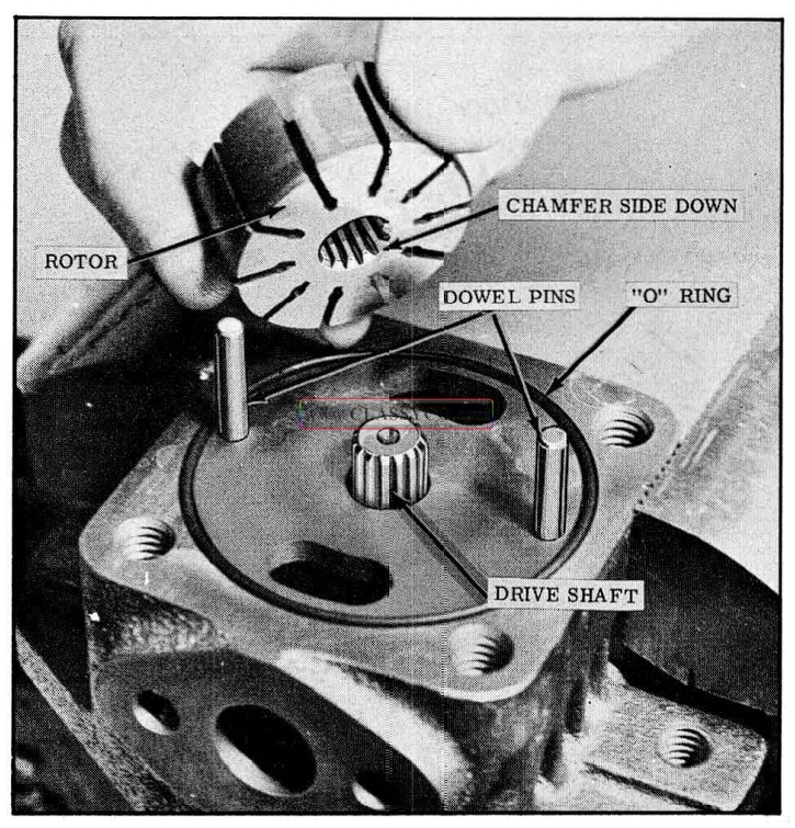
1957 Oldsmobile Rotor Installation
- Assemble the vanes in the rotor slots with the radius edge facing outward. (See Fig. 5-80)
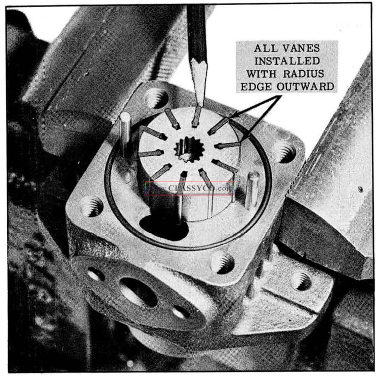
1957 Oldsmobile Installation of Vanes
NOTE: If wear is apparent on the vanes, the worn sides should face the drive side of me rotor slot, (trailing edge of the slot as the rotor is turned counter-clockwise when viewed from the rear of the pump.
- Position cam ring over dowel pins with scribe marks aligned.
NOTE: The arrow on the cam ring should point in a clockwise direction when pump is viewed from the front.
- Place the pressure plate on the cam ring over the dowel pins. (See Fig. 5-81)
1957 Oldsmobile Installing Pressure Plate
- Place flow control spring into bore of pump and POSITION PLUG END OF FLOW CONTROL VALVE INTO SPRING.
- Compress spring so that flow control valve enters the bore in the cover, then install wooden dowel to retain valve in cover.
- Install new “O” ring in pump cover, then with scribe marks aligned install the cover over me pressure plate and tighten attaching bolts finger tight. Remove wooden dowel.
- Make sure that reservoir mounting surfaces are parallel, then tighten pump cover attaching bolts 25 to 30 ft. lbs.
- Install new “O” ring on the union fitting, then install fitting into pump cover.
- Position reservoir mounting gaskets on the pump assembly.
- Position the manifold inside of reservoir and place reservoir on top of mounting gaskets with all holes aligned, then install and torque the 4 attaching screws 8 to 10 ft. lbs.
- Clip strainer and retainer as an assembly on return tube. (See Fig. 5-82)
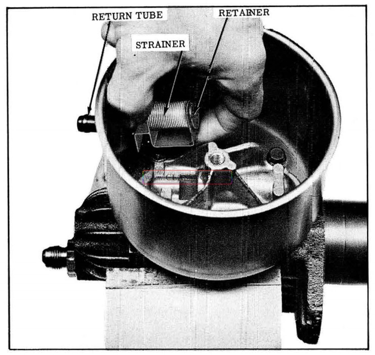
1957 Oldsmobile Installing Strainer and Retainer
- Assemble the reservoir cover and gasket finger tight, then cap inlet and outlet fittings to prevent entrance of dirt until the pump is installed on the car.
HORN CONTACT’ ASSEMBLY AND STEERING WHEEL
REMOVAL
Horn wire should be disconnected to prevent blowing of horn. The horn cap on the standard steering wheel may be removed by inserting a sharp instrument underneath the edge of the cap and prying upward. Removal of the steering wheel nut will permit removal of the contact assembly.
The deluxe horn ring cap is retained to the horn ring hub by a screw, which is accessible from the underside of the cap.
The steering wheel nut will have to be removed in order to remove the horn contact assembly or steering wheel. (See Fig. 5-83)
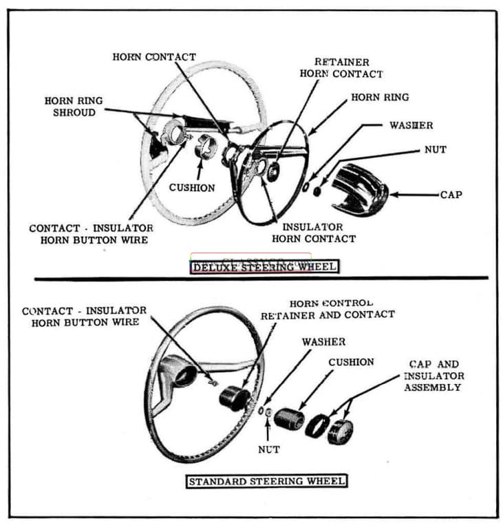
1957 Oldsmobile Steering Wheel Assemblies
A steering wheel puller should be used to facilitate removal of the wheel. (See Fig. 5-84)
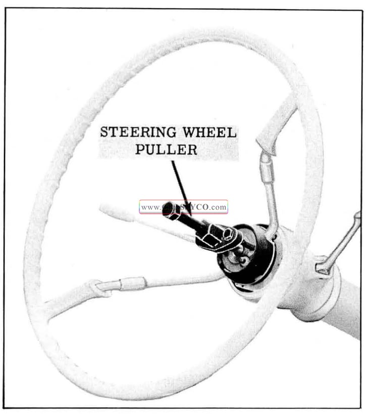
1957 Oldsmobile Steering Wheel Removal
UPPER BEARING – Remove and Replace
- Remove steering wheel.
- Disconnect horn wire from chassis wiring harness.
- Remove horn wire clamp from mast jacket.
- Pry upper bearing from retainer and discard.
To replace, reverse the above procedure. Use Tool J -2587-8 and a standard washer having a 7 /8″ inside diameter to install new bearing. (See Fig.5-85)
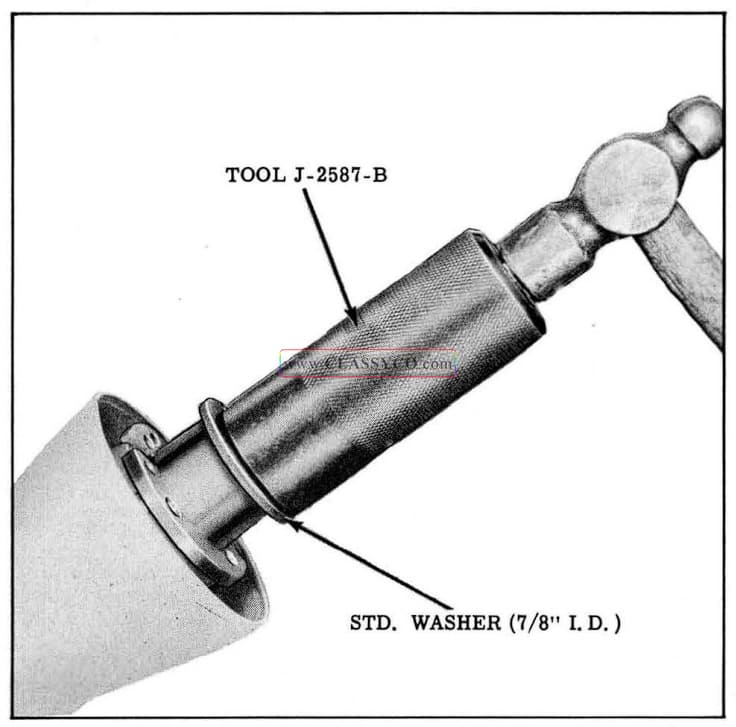
1957 Oldsmobile Upper Bearing Installation
MAST JACKET
REMOVE AND REPLACE
- Disconnect battery.
NOTE: On cars equipped with standard brakes, disconnect positive battery cable at junction block on left fender filler plate. Dis connect solenoid lead wire (purple) from wiring harness, then pull cable through sleeve on mast jacket lower clamp.
- Disconnect rod from lower shift lever.
- On cars equipped with Syncro-Mesh, disconnect rod from cross shift lever. (See Fig. 5-86)
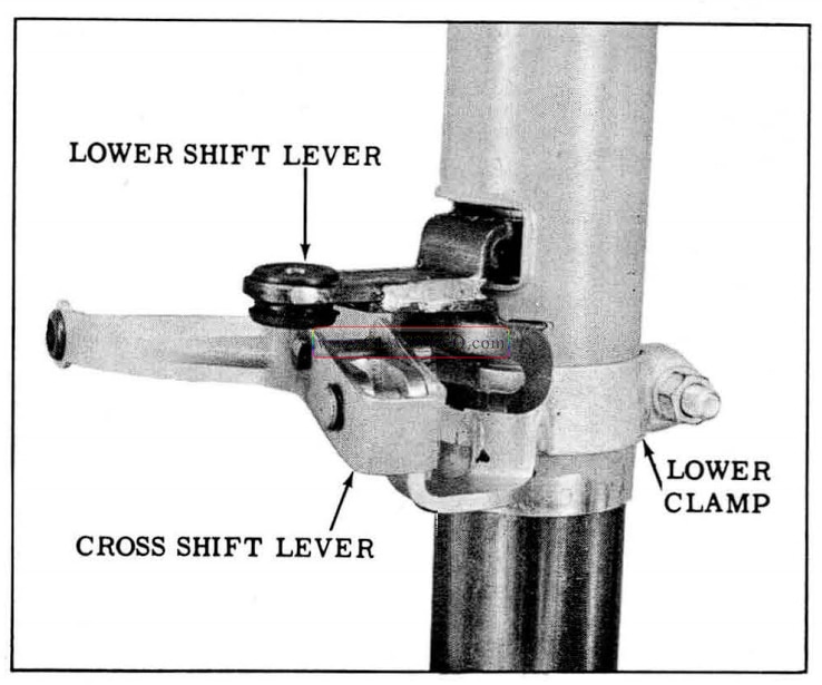
1957 Oldsmobile Syncro-Mesh Shift Levers
- Disconnect the horn wire from chassis wiring harness and the turn signal wires from turn signal switch on mast jacket.
- If equipped with Hydra-Matic, disconnect the wires from the combination neutral safety and back -up switch on mast jacket. Remove cap from mast jacket bracket, then remove the H -M indicator needle from the shifter tube. (See Fig. 5-87)
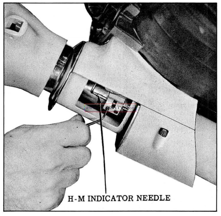
1957 Oldsmobile H-M Indicator Needle Removal
- Loosen mast jacket grommet and retainer hold down clamp.
- If equipped with power brakes, remove pedal and pedal bracket. Remove power brake cylinder mounting bolts, permitting power brake unit to rest on car frame.
- Remove mast jacket cover plate.
- Remove clamp from mast jacket bracket.
- If equipped with standard steering, loosen lower clamp.
- Slide mast jacket off steering column.
NOTE: If steering shaft or flexible coupling (power steering only) is to be removed, scribe an alignment mark on the coupling flange ad jacent to the large flexible coupling bolt so that the parts may be lined up upon reassembly. (See Fig. 5-88)
1957 Oldsmobile Alignment Marks (3)
To replace mast jacket, reverse the above procedure.
NOTE: Before tightening the upper and lower clamps, position the mast jacket (manual steering) or lower bearing retainer (power steering), to provide 1/8″ to 3/16″ clearance between the steering wheel and turn signal collar.
Adjust turn signal switch. (See ELECTRICAL SECTION)
On Hydra-Matic equipped cars, check and adjust neutral safety switch. (See ELECTRICAL SECTION) Align the H-M indicator needle (See INSTRUMENTS AND RADIO SECTION)
MAST JACKET DISASSEMBLE AND ASSEMBLE
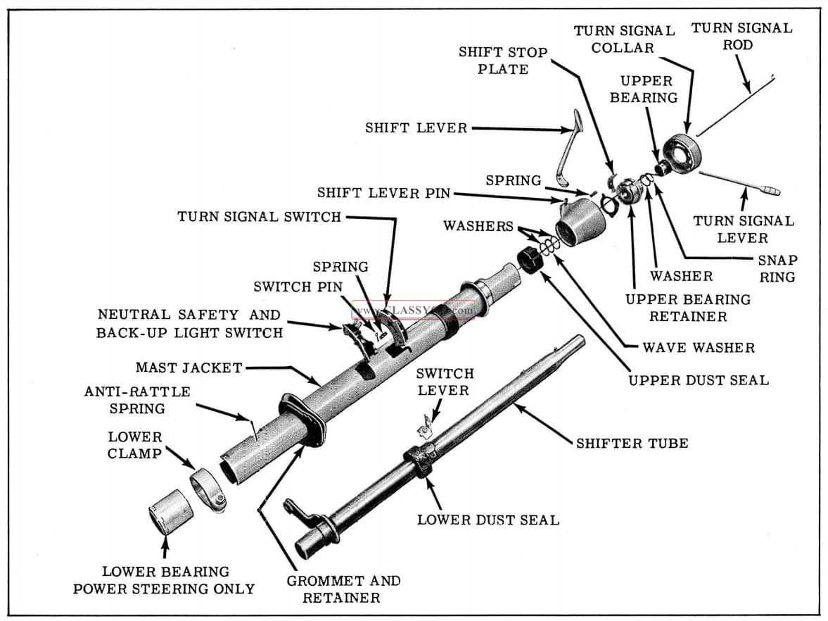
1957 Oldsmobile Mast Jacket – Hydra-Matic
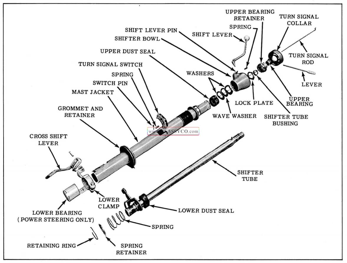
1957 Oldsmobile Mast Jacket Syncro-Mesh
- Remove turn signal switch from side of mast jacket. Remove the switch pin and spring from the turn signal rod.
- Remove turn signal collar mounting screws, then pull turn signal collar and rod from the mast jacket.
- If necessary to disassemble the turn signal collar, move the turn signal lever to the left turn position and slide the turn signal rod from the collar. (See Fig. 5-91) Unscrew the lever from the collar, then pry the ring from the collar. From the upper side of the collar, remove the plate.
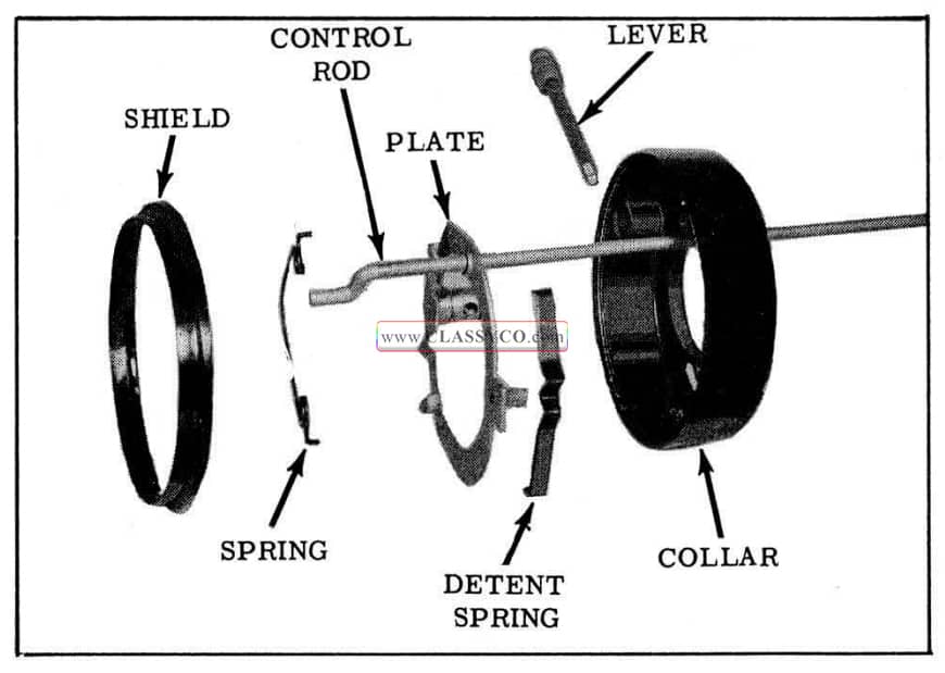
1957 Oldsmobile Turn Signal Collar
- On Hydra-Matic equipped cars, remove the combination neutral safety and back-up light switch from the mast jacket. Remove the switch lever from the shifter tube.
- Remove the upper bearing and horn wire from the mast jacket using a screw driver.
- On Hydra-Matic models, remove the shifter tube snap ring and washer from inside the upper bearing retainer.
- Remove the 3 upper bearing retainer screws, then remove the upper bearing retainer. (See Fig. 5-92)
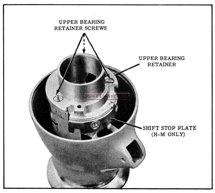
1957 Oldsmobile Upper Bearing Retainer
NOTE: If necessary, the shift stop plate (Hydra-Matic models) or the shifter tube bushing (Syncro-Mesh models) can be re moved from the upper bearing retainer at this time.
- Rotate the upper bearing retainer lock plate clockwise, then remove lock plate.
- On Syncro-Mesh models, support shifter bowl and drive shift lever pin from bowl. Remove shift lever and spring from bowl. Remove anti-rattle from shift lever.
- Pull shifter bowl, thrust washers and wave washer from shifter tube. If necessary, remove upper felt dust seal.
- On Hydra-Matic models, support shifter bowl and drive shift lever pin from bowl. Remove shift lever and spring from bowl.
- If car is equipped with power steering, loosen lower clamp and remove lower bearing retainer assembly.
- Remove lower clamp.
- On Syncro-Mesh models, remove retaining ring, spring retainer, spring, and shifter tube from lower end of mast jacket.
- On Hydra-Matic models, remove anti-rattle spring and shifter tube from lower end of mast jacket.
- If necessary to service the lower bearing retainer assembly (power steering), the bearing assembly and dust seal may be driven out of the retainer. (See Fig. 5-93) To assemble the bearing assembly, saturate the felt on the bearing and the felt dust seal with engine oil. Place the bearing in the bearing retainer, then tap the dust seal and dust seal retainer into the bearing retainer.
To reassemble mast jacket, reverse the above procedure. Apply a thin coat of Lithium Soap Grease to all frictional parts. Install upper bearing using Tool J-2587 -B and standard washer having a 7/8″ inside diameter. (See Fig. 5-85)
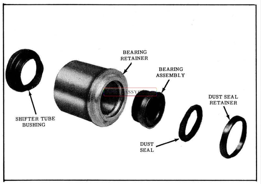
1957 Oldsmobile Lower Bearing Retainer Assembly
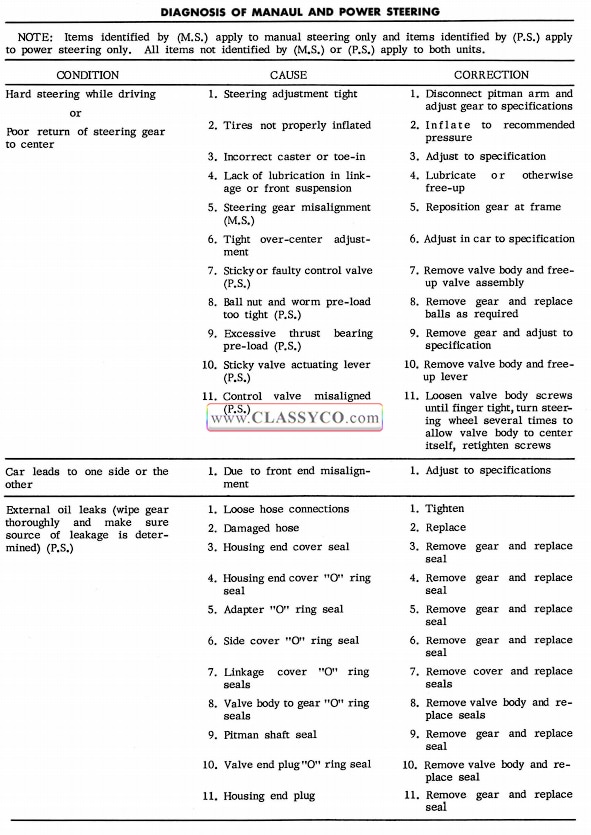
1957 Oldsmobile Diagnosis of Manual and Power Steering 1
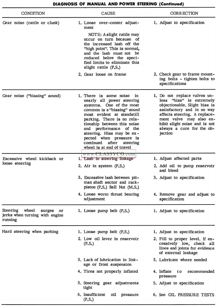
1957 Oldsmobile Diagnosis of Manual and Power Steering 2
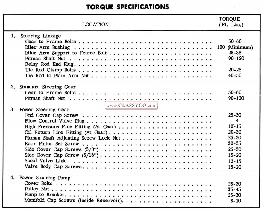
1957 Oldsmobile Steering Torque Specifications