CLUTCH
GENERAL DESCRIPTION (Fig. 10-1)
The single plate, dry disc clutch is mounted with a free sliding fit on the Syncro-Mesh Transmission mainshaft. Engagement of the clutch is accomplished by a spring loaded pressure plate which forces the driven plate against the flywheel.
When the clutch pedal is depressed, the clutch release yoke moves the release bearing forward on the transmission bearing retainer sleeve until the bearing moves the inner end of the release levers. The release levers pivot at yokes (attached to the cover plate) and overcome the pressure spring force to move the pressure plate rearward to disengage the driven plate.
When the clutch pedal is released, the clutch release yoke moves the release bearing away from the release levers and the pressure springs force the driven plate against the flywheel to engage the clutch. The engagement of the clutch is cushioned by springs mounted between the facings of the driven plate. As the speed of the engine increases, the weighted outer ends of the release levers, through centrifugal force, add to the spring pressure exerted on the driven plate, thereby in creasing clutch pressure, which increases the clutch torque capacity.
Torsional vibrations from the engine are pre vented from being transmitted to the transmission by coil springs mounted in the hub of the driven plate. Balance is obtained by means of narrow sheet metal strips crimped around the webs of the driven disc; grinding of the edges should NOT be attempted as a means of balancing.
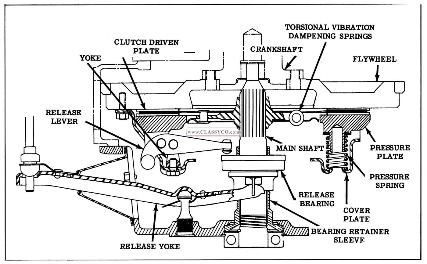
1957 Oldsmobile Clutch Assembly
CLUTCH AUXILIARY SHAFT AND LINKAGE (Fig. 10-2)
The clutch auxiliary · shaft is so designed as to permit engagement and disengagement of the clutch without being affected by engine movement on its flexible mountings.
The assembly consists of a stamped steel auxiliary shaft with a pivot pin at each end, three integral arms, and a combination clutch pedal pressure reducer and return spring.
The auxiliary shaft floats in both of its two sup porting brackets, and endwise shaft movement is kept within reasonable bounds by felt washers.
One arm on the auxiliary shaft is connected to the clutch pedal by a link. The other arm of the auxiliary shaft is connected to the clutch release yoke by an adjustable rod. Adjustment for clutch lash is made on this rod.
The combination pressure reducer and return spring attaches to the third auxiliary shaft arm and to the second frame cross member.
Lubrication of the auxiliary shaft assembly is provided by means of the felt washers at each end of the shaft. Engine oil should be applied to the felt washers at each lubrication interval.
A high pressure lubrication fitting is provided on the underside of both the clutch and brake pedals for their lubrication.
CLUTCH PEDAL ADJUSTMENT
Clutch pedal free travel is the distance from the released position to the point where the release pearing contacts the clutch release levers. (When additional effort is required to move the pedal)
Clutch pedal free travel should be 1″ to 1-1/ 4″.
If the clutch pedal free travel is outside of the above specification, loosen the lock nut on the adjustable rod and turn adjusting nut until free travel is correct, then tighten lock nut. (See Fig. 10-2)
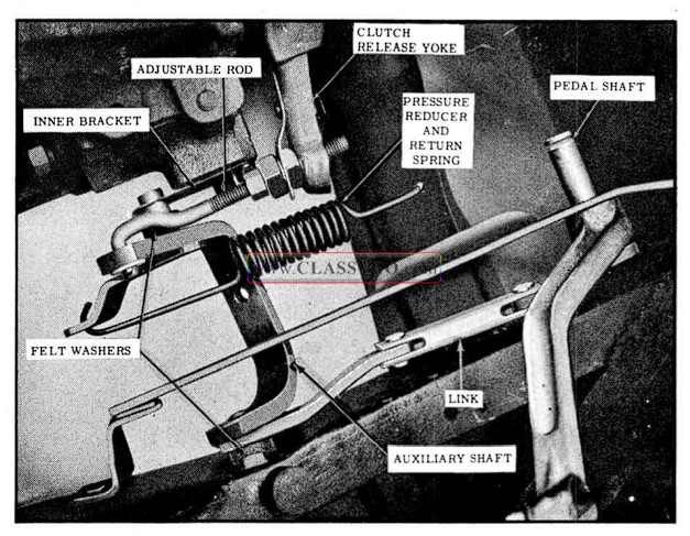
1957 Oldsmobile Clutch Auxiliary Shaft Assembly
CLUTCH AUXILIARY SHAFT REMOVE AND REPLACE
To remove the clutch auxiliary shaft proceed as follows:
- Disconnect adjustable rod and link from auxiliary shaft.
- Disconnect pressure reducer spring by revolving auxiliary shaft backwards.
- Remove the inner auxiliary shaft bracket 3.
- Slide shaft out of frame bracket.
To replace, reverse sequence of operations, lubricating felt washers at each end of shaft and making sure that all parts are free. Adjust clutch pedal free travel.
CLUTCH REMOVAL AND REPLACEMENT (Transmission Removed)
- Remove transmission bearing retainer sleeve.
- Remove left engine filler plate, engine breather pipe, and the right and left rear lower flywheel housing bolts.
- Remove return spring and disconnect adjustable rod at yoke. (See Fig. 10-2)
- Install Engine Rear Support Tool BT-28, as shown in Fig. 10-3.
- Remove engine rear mount bolts at clutch housing and remove frame cross-member by removing three bolts at each end.
- Remove eight bolts securing clutch housing to flywheel housing, and remove clutch housing and release yoke.
- Mark flywheel and clutch cover for correct positioning at reassembly.
- Remove six clutch assembly to flywheel bolts and remove clutch.
To install, reverse sequence of operations. Use an old transmission ma in shaft to align clutch disc while tightening clutch to flywheel. Lubricate clutch shaft pilot bearing and bearing surface of release levers with Special Lubricant #563598. Adjust transmission shaft linkage, and adjust clutch pedal free travel 1″ to 1-1/4″. Lubricate clutch release bearing as outlined in the Lubrication Section.
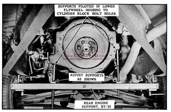
1957 Oldsmobile Engine Support Tool in Position
CLUTCH DISASSEMBLY AND INSPECTION (Fig. 10-4)
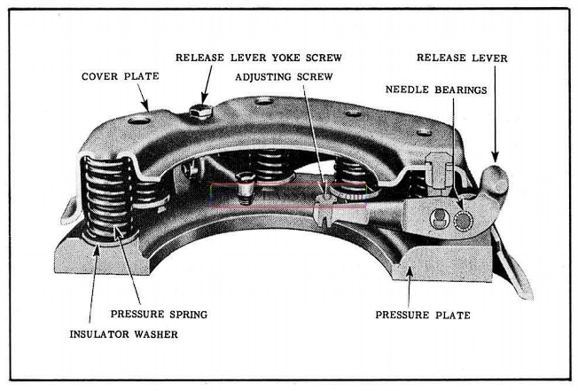
1957 Oldsmobile Clutch Details
- After removing clutch from engine, mark the cover and pressure plate with a punch if these are both to be reused, so that the two parts may be reassembled in the same relative position.
- Place the clutch assembly on an arbor press with the pressure plate resting on a block so that cover plate is free to move downward without obstruction. Place a bar or block across the top of the cover, resting on the spring bosses. (See Fig. 10-5)
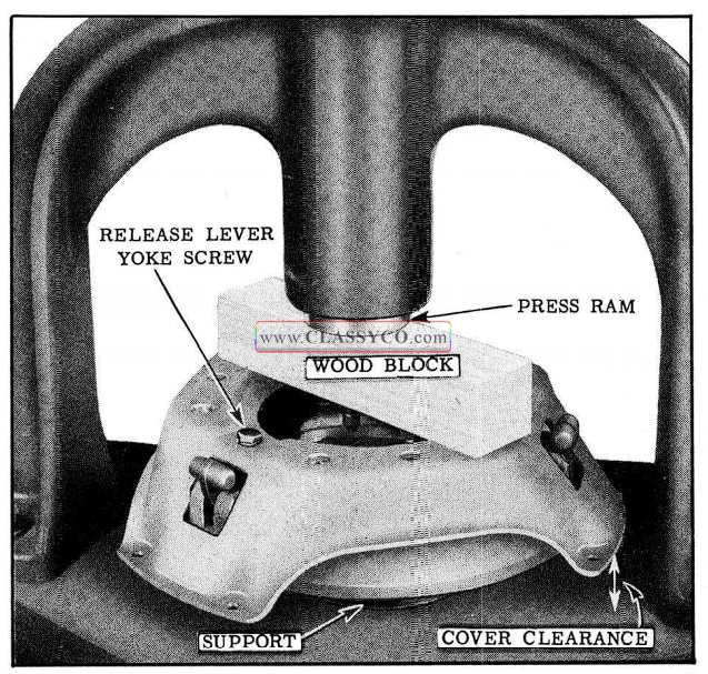
1957 Oldsmobile Release Lever Yoke Screw Removal
- Lower the ram of the press and while holding it under compression remove the release lever yoke screws and release the pressure slowly to prevent the springs from flying out.
- The cover can then be lifted off and all parts will be available for inspection. (See Fig. 10-6) Release levers can be removed from the pressure plate and yokes from the release levers by carefully hack-sawing the large upset ends off the pins holding these parts together. A dummy pin the width of the lever should be used for removal of the old pins. In this way the needle bearings can be kept from falling from the lever during removal of the pin.
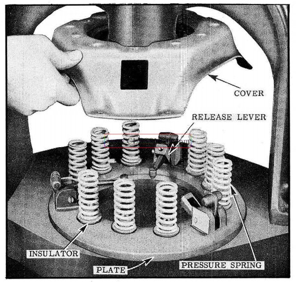
1957 Oldsmobile Removing Cover and Springs
- Inspect the pressure plate springs and replace in complete sets if they show signs of overheating due to clutch slipping. If the springs have been overheated, the paint will be burned off or they will show a pronounced blue color, indicating the temper has been drawn.
- Inspect the driven plate and replace if the facings are worn nearly to the rivet heads.
NOTE: Installation of clutch driven plate facings is not recommended, as it is difficult to obtain balance and flat parallel faces.
- Inspect clutch driven plate cushion springs for weakness, cracks, or fatigue failure, and replace plate assembly if any of these conditions are found.
ASSEMBLY OF CLUTCH
- Mount the yoke on each clutch release lever, and all levers to the pressure plate using new pins to replace those hack-sawed off in the disassembly operation. New copper thrust plates should be installed on lugs at time of lever replacement. Be sure that pivot pins and driving shims are properly installed as shown in Fig. 10-7. The service replacement pins are like original pins except that they are drilled for cotter pins, eliminating the need for upsetting. A short length of pin cut to the width of the release lever should be used to hold the needle bearings in place while the new pin is being installed.

1957 Oldsmobile Assembly of Lever to Plate
- Place pressure plate in arbor press and set clutch springs on it in a vertical position, seating them on the insulators resting on the small pressure plate bosses.
- Place a small amount of Lubriplate on driving lugs.
- Place cover on top of assembled parts, taking care that release levers are in position and that tops of pressure plate springs are properly seated in cover.
- Position each yoke with respect to the cover and place a small pin through hole in cover into hole in yoke so that yoke does not drop out of position as cover is depressed.
- Lay a bar across cover and slowly compress assembly, taking particular care to assure that pressure plate lugs are properly guided, without bind, through the holes in cover. (See Fig. 10-8)
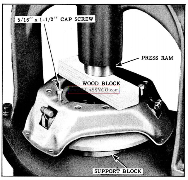
1957 Oldsmobile Compressing Pressure Plate
- Remove the small pins used to hold release lever yokes in position and install cap screws, being sure to hold yoke square while tightening.
- Release and apply pressure on assembly several times so that all moving parts will settle to their correct working position.
- Remove pressure plate assembly from press; check, and, if necessary, adjust the clutch release levers.
ADJUSTMENT OF CLUTCH RELEASE LEVERS
- Before adjustment of clutch release levers is attempted, levers must be worked several times to center the bearings.
- Place Gauge J-4389 on a flywheel in the position normally occupied by the driven plate.
- Mount pressure plate assembly to flywheel, alternately tightening attaching screws one or two turns at a time so as not to distort pressure plate assembly cover.
- Lay a short straightedge across the center boss of the gauge as a guide for positioning release levers. (See Fig. 10-9)
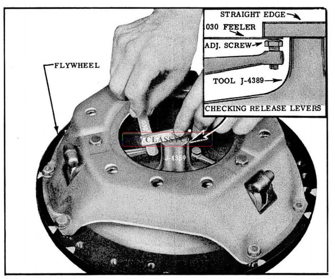
1957 Oldsmobile Checking Release Levers
- The level of bearing surfaces on all lever adjusting screws should be from .0000 ” to .0625″ below the level of the gauge center boss, and each lever should lie within.015″ of the other two levers.
- If the levers are not more than.025″ out of plane, adjustment can be made by lightly tapping· the release yoke mounting screw heads, using an 8 ounce hammer, in order to bend the pressure plate cover a small amount until all levers are in the same plane within .015″.
If the levers are more than .025″ out of plane or do not lie within the .0000″ to .0625″ below the center boss, it will be necessary to adjust the release lever screws as follows:
a. Using a standard hack-saw blade, remove the original stakes from the required release lever adjusting screws.
b. Adjust screw (or screws) until all levers are within.015″ of each other and lie not more than .0625″ below the level of the gauge center boss.
c. With head of screw resting on a solid block use a blunt chisel to restake the screw to the lever. A lever can be restaked only once because of the limited stock around the adjusting screw, and it will be necessary to replace the lever if, after the first restaking, the adjustment is incorrect.
d. Recheck release lever adjustment as outlined in steps 1 through 5.
RELEASE YOKE, REMOVE AND REPLACE (Fig. 10-10)
To remove the clutch release yoke, proceed as follows:
- Remove transmission and bearing retainer sleeve.
- Disconnect adjusting rod from yoke.
- Remove the clutch housing.
- Snap yoke off ball stud by pushing in on end of yoke, then remove yoke.
To replace, reverse sequence of removal operations. Lubricate clutch release bearing as outlined in the Lubrication Section. Check and adjust clutch pedal free travel. (Refer to Clutch Pedal Adjustment)
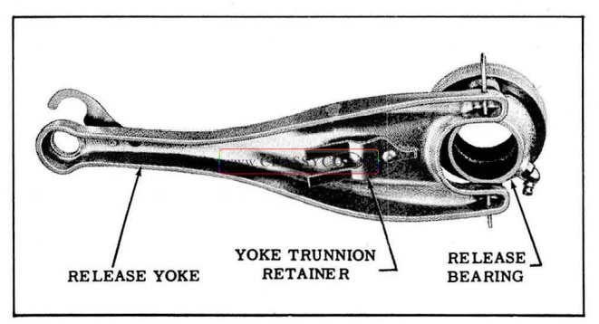
1957 Oldsmobile Clutch Yoke Assembly
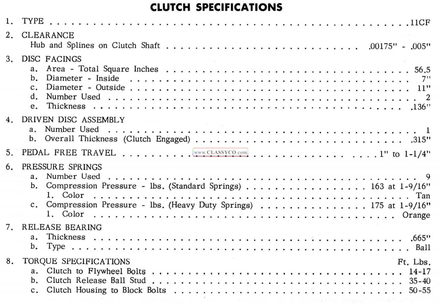
1957 Oldsmobile Clutch Specifications
1957 Oldsmobile S88 Fiesta (DHW)