BODY
WINDSHIELD AND MOLDINGS
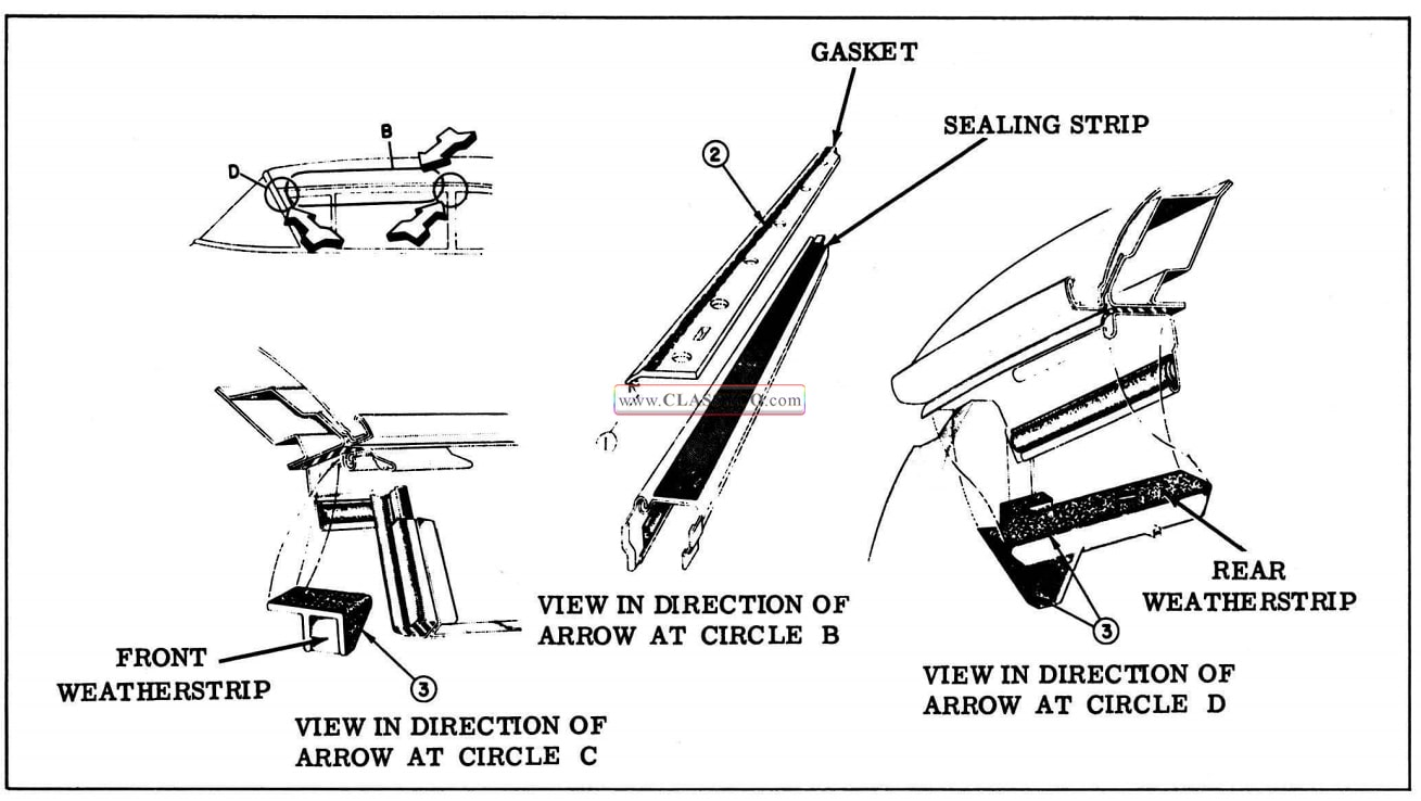
WINDSHIELD GARNISH MOLDINGS AND REAR VIEW MIRROR SUPPORT
Remove and Install
The windshield garnish moldings are secured to the body with readily accessible screws. Be cause of design, the garnish moldings are removed and installed in a definite sequence. The garnish moldings consist of the following parts: side garnish molding, right and left; upper garnish molding, right and left; lower garnish molding, right and left. The rear view mirror support attaches to the body at the upper center of the windshield opening. The side sections of the support are over-lapped by the upper garnish moldings.
- Cover instrument panel, front seat, and adjacent paint and trim parts.
- Remove side garnish moldings.
- With side garnish moldings removed, remove upper garnish moldings, right and left, then remove rear view mirror support.
- With side garnish moldings removed, remove lower garnish moldings, right and left.
- To install, reverse removal procedure and remove protective coverings.
WINDSHIELD REVEAL MOLDINGS (Except Convertible)
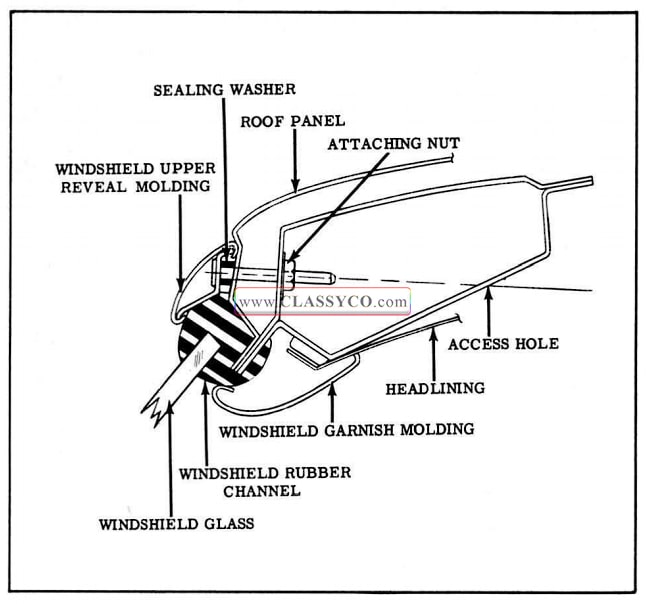
The windshield reveal moldings consist of the following parts: windshield upper reveal molding, right and left; and windshield lower reveal molding, right and left. Center escutcheons are integral on the right upper and lower reveal moldings. Each upper reveal molding is secured to the body by means of bolt and clip assemblies and attaching nuts across the top of the windshield; by means of screws along the front hinge pillars; and by a slide-on retention at the lower end. Access to the attaching nuts is gained by loosening the headlining over the windshield. The lower reveal moldings are secured to the body by means of clips and screws which are accessible outside of the body.
WINDSHIELD UPPER REVEAL MOLDING (Except Convertible)
Remove and Install
- Cover instrument panel, seat, hood and fenders.
- Remove side garnish moldings, upper garnish moldings, and rear view mirror support.
- Remove sunvisors and supports.
- Carefully remove tacks and loosen headlining sufficiently over windshield to gain access to upper reveal molding attaching nuts. (See Fig. 17-1)
- Remove upper reveal molding attaching nuts. (See Fig. 17-1)
- Remove attaching screws securing upper reveal molding along front body hinge pillar and remove windshield lower corner gutter.
- Disengage upper reveal molding from end of lower reveal molding and remove molding.
- To install, reverse removal procedure.
NOTE: If necessary, replace bolt and clip assembly sealing washers. (See Fig. 17-1) Seal screw holes with body caulking compound.
1957 Oldsmobile Windshield and Upper Reveal Molding
WINDSHIELD LOWER REVEAL MOLDING
Remove and Install
- Cover hood and fenders.
Protect adjacent paint finish with masking tape.
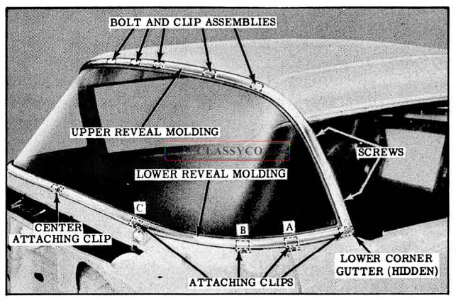
- Open door. Remove attaching screws securing upper reveal molding along front body hinge pillar. (See Fig. 17-2)
- Disengage upper reveal molding from lower reveal molding sufficiently to remove lower reveal molding and attaching screw. (See Fig. 17 -2)
- Remove screw, “A” from lower reveal molding attaching clip which is readily accessible with door open. (See Fig. 17-2)
1957 Oldsmobile Reveal Molding Attachment
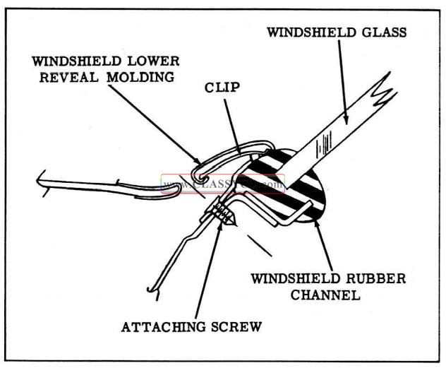
- To disengage lower reveal molding from attaching clip, “8”, Fig. 17-2, slide lower re veal molding outward for distance of about one inch and raise molding. The cross-section of this clip is shown in Fig. 17- 3.
1957 Oldsmobile Lower Reveal Molding Attachment
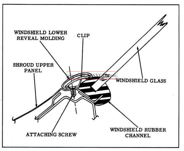
- Remove lower reveal molding from body by sliding molding off attaching clip, “C”, Fig. 17-2. The cross-section attachment of this clip is shown in Fig. 17-4.
NOTE: The left lower reveal molding slides into the integral center escutcheon of the right lower reveal molding. The right molding is secured at the body center line by means of a center attaching clip. (See Fig. 17-4)
1957 Oldsmobile Lower Reveal Molding Attachment (2)
- To install, reverse removal procedure with the following exceptions:
a. Right lower reveal molding is installed before left molding.
b. All lower reveal molding attaching clips are secured to body with screws. When in stalling attaching clips, such as during windshield glass removal and installation operation, seal screw holes with medium bodied sealer.
WINDSHIELD SIDE REVEAL MOLDING (Convertible)
Remove and Install
- Lower top.
- Cover instrument panel and seat.
- Open door. Remove screws securing side reveal molding to front body hinge pillar and remove windshield lower corner gutter.
- Disengage side reveal molding from upper and lower reveal moldings and remove molding.
- To install, reverse removal procedure. Seal attaching screw holes with body caulking compound. Remove protective covers.
WINDSHIELD HEADER MOLDINGS (Convertible)
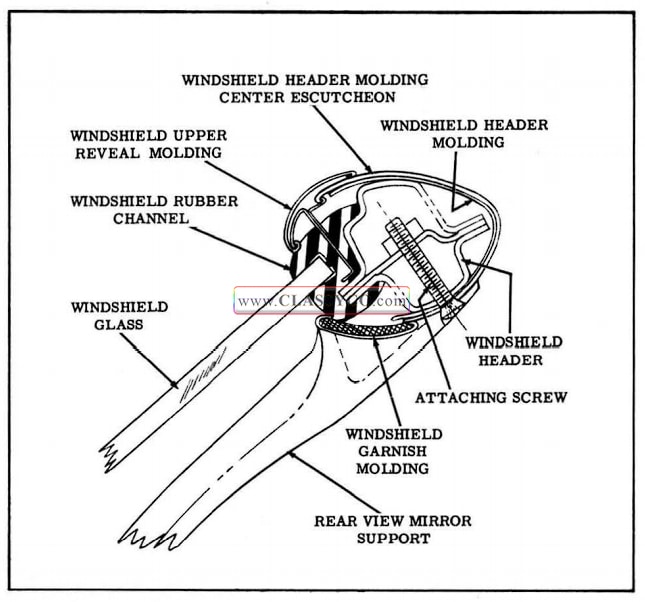
1957 Oldsmobile Windshield Header
Remove and Install
The windshield header moldings, of stainless steel construction are made up of three sections: A right and left section and a center escutcheon.
- Cover instrument panel and seat.
- Lower top.
- Remove windshield side and upper garnish moldings and remove rear view mirror support.
- Remove sun visors, supports, and rod retainers.
- Remove front roof rail lock strikers (2).
- Remove side reveal moldings.
- Remove windshield header molding center escutcheon.
- From each end of upper reveal molding remove screw and shim which also secures windshield header molding.
- Remove windshield header moldings, right and left, by disengaging front edges of moldings from windshield reveal molding.
- To install, reverse removal procedure.
NOTE: Seal attaching screw holes with body caulking compound.
WINDSHIELD GLASS
The windshield is secured to the body by a one-piece rubber channel. With the exception of the convertible styles, the windshield reveal moldings are installed after the windshield installation. On convertible styles, the upper reveal molding is installed in the rubber channel before the windshield assembly is installed.
Remove
- Lower top on convertible styles.
- Cover front seat, instrument panel, fenders and hood.
- Remove windshield wiper arm and blade assemblies.
- Remove windshield garnish moldings and rear view mirror support.
- Remove windshield reveal moldings.
- Apply outward pressure close to edge of glass with palm of hand and, using putty knife, work lip of rubber channel over pinchweld flange. (See Fig. 17-6)
- Carefully remove windshield assembly from body and place on covered bench.
NOTE: On convertible styles, remove upper reveal molding.
- Remove rubber channel from glass.
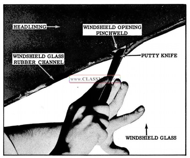
1957 Oldsmobile Windshield Glass Removal
Checking Body Windshield Opening
It is important that the size and contour of the body windshield opening be checked thoroughly before the installation of a replacement windshield glass. The procedure below outlines the method which can be used to check the windshield opening:
- Check windshield rubber channel for any irregularities.
- Clean off old sealer from around windshield opening and check entire body opening flange for irregularities.
- Support and center new glass in windshield opening with six wood spacers located as shown in Fig. 17-7.
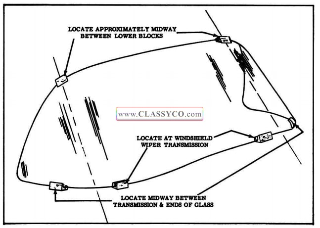
1957 Oldsmobile Spacer Position for Pinchweld Alignment
CAUTION: Be certain that glass does not strike body metal during this temporary installation. Chipped edges can result in future breaks.
- Fig. 17-8 shows a typical cross-section taken through glass and body opening. Spacing be tween glass and metal should be as follows:
a. Between inside surface of glass and body opening flange spacing should be uniform and from 3/16″ to 1/4″.
b. Between edge of glass and body opening, spacing should be uniform and when measured in plane of glass should be 5/16 ” to 7/16″. - Mark any sections of body to be re-formed (masking tape applied to body opening can be conveniently marked without damage to the painted surfaces), remove glass, and reform opening as required.
- Check windshield opening again as outlined in step 4.
NOTE: MARK THE GLASS AND BODY so that glass can be centered accurately in opening when installed.
1957 Oldsmobile Windshield Glass to Pinchweld Clearances
Install
- Check windshield drain gutter and both left and right drain hose openings for obstructions and clean out if necessary.
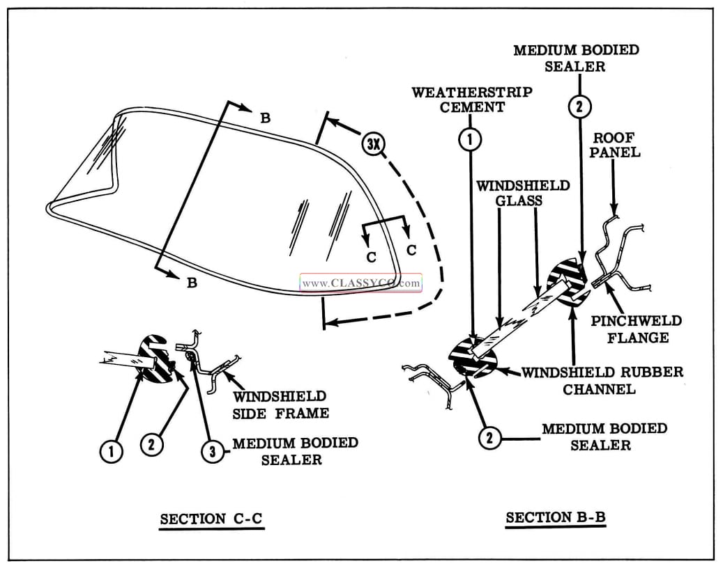
- Install rubber channel on glass. (See Fig. 17 -9) On convertible styles, install center upper reveal molding in rubber channel.
1957 Oldsmobile Windshield Glass Installation
- Insert strong cord in pinchweld cavity of rubber channel completely around windshield. Form loop with cord at bottom center of glass and tape loop to inside of glass. (See Fig. 17-10)
1957 Oldsmobile Cord Removal
- Apply a ribbon of medium-bodied sealer completely around base of rubber channel as indicated at 2 in Fig. 17-9. In addition, apply a ribbon of sealer along pinchweld flange as indicated at 3, Fig. 17-9. This seal is to be applied at each side of windshield opening as indicated by distance 3X.
- Position glass in opening and center glass between windshield pillars.
- Use care when positioning glass close to wind shield opening for cord pulling operation.
NOTE: Do not use excessive pressures or blows of any type during or after glass Installation. Have helper inside pull cord slowly in following sequence to seat lip of channel over pinch weld: (See Fig. 17 -10)
a. Along bottom, “a” to point “b”, as shown.
b. Along bottom, “a” to point “c”, as shown.
c. Along top, “c” to point “d “, as shown.
d. Along top, “b” to point “d”, as shown.
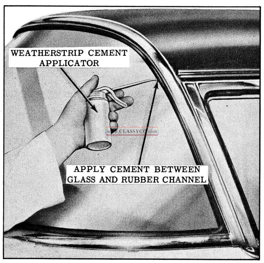
7. Use weatherstrip cement to seal between outside lip of rubber channel and glass. (See Fig. 17 -11)
8. Clean off all excess sealer and install previously removed parts. Remove protective coverings.
1957 Oldsmobile Sealing Channel
WINDSHIELD WIPER ASSEMBLIES
WINDSHIELD WIPER MOTOR
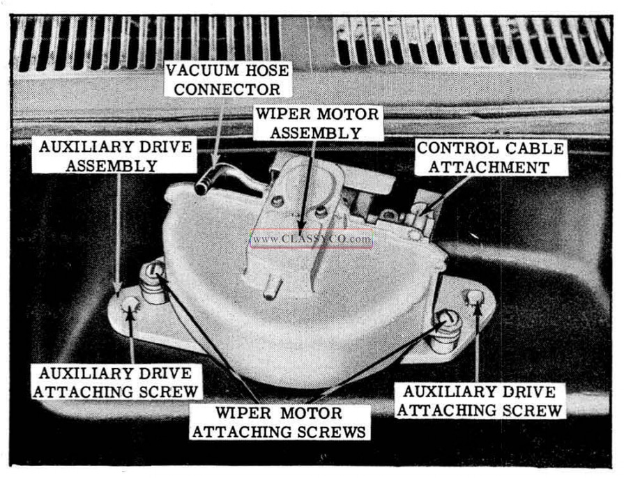
The windshield wiper motor attaches to the auxiliary drive at the forward side of the dash panel.
Remove
- Remove wiper motor to auxiliary drive attaching screws to disconnect motor from drive.
- Disconnect wiper motor control cable and vacuum hose, and remove motor. (See Fig. 17 -12)
Install
- Connect wiper motor control cable and vacuum hose.
- Position wiper motor and install motor to drive attaching screws. (See Fig. 17 -12)
- Check operation of wiper motor.
1957 Oldsmobile Wiper Motor Assembly
WINDSHIELD WIPER MOTOR AUXILIARY DRIVE ASSEMBLY
The auxiliary drive assembly attaches to the forward side of the dash panel. The wiper motor attaches to the drive at this location. The drive assembly consists of two pairs of pulleys which are designed to operate simultaneously as an integral unit.
Remove
- Adjust wiper transmission cables to slack pos1t10n. See “Wiper Transmission Cable Adjustment “.
- Observe and note how right and left transmission cables attach to auxiliary drive pulleys to assure proper installation, then disconnect cables from pulleys. (See Fig. 17 -13)
- Disconnect windshield wiper motor from auxiliary drive by removing motor attaching screws. (See Fig. 17-12)
- Remove auxiliary drive to dash panel attaching screws. Break seal between auxiliary drive and gasket on dash panel, and remove drive. (See Fig. 17-12)
Install
- If necessary, cement new auxiliary drive gasket to body. Use weatherstrip cement.
- Position auxiliary drive and install drive attaching screws. (See Fig. 17 -12)
- Position windshield wiper motor on auxiliary drive and install attaching screws. (See Fig. 17 -12)
- Inside of body, attach wiper transmission cables to auxiliary drive.
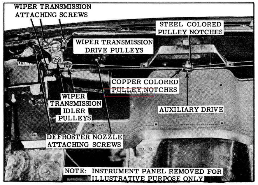
IMPORTANT: The “right” wiper transmission cables attach to the “outer” two (of four) drive pulleys and the “left” wiper transmission cables attach to the “inner” two (of four) drive pulleys as shown. Also, copper colored cable ends must be installed to copper colored pulley notches and steel colored cable ends to steel colored pulley notches. (See Fig. 17-13)
1957 Oldsmobile Wiper Cable Installation
- Adjust cable tension as required. See “Wiper Transmission Cable Adjustment”.
- Check auxiliary drive for proper operation.
WINDSHIELD WIPER TRANSMISSION
The windshield wiper transmission has been redesigned and attaches to the body by means of a spanner nut. Since an additional spanner nut is required to secure the escutcheon, the new transmission service procedures now involve two spanner nuts, each of a different size. The new transmissions are designed with “idler” pulleys in addition to “drive” pulleys which play an important role in routing the power from the wiper motor to the windshield wipers. The new wiper transmissions retain the “push-button ” cable adjustment feature.
Remove
- Cover front seat, hood and fenders.
- Remove wiper arm and blade assemblies.
- Adjust wiper transmission cables to slack position. See ” Wiper Transmission Cable Adjustment”.
- Observe and note attachment of transmission cables at auxiliary drive pulleys to assure proper installation, then disconnect cables from auxiliary drive pulleys. (See Fig. 17 -13)
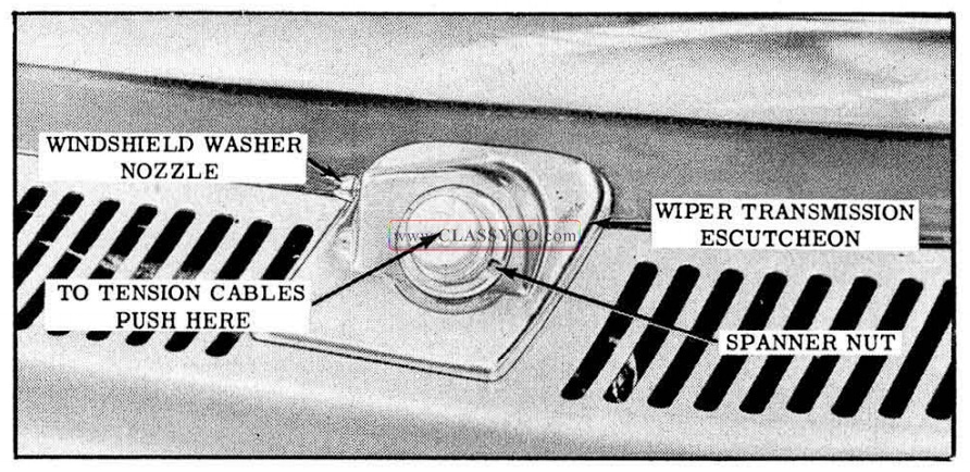
- Using Tool J -6592, remove wiper transmission escutcheon spanner nut; then remove escutcheon. Disconnect washer hose to remove escutcheon. (See Fig. 17 -14)
1957 Oldsmobile Windshield Wiper Transmission Assembly
- Using Tool J -6592, remove wiper transmission spanner nut and spacer. (See Fig. 17 -15)
1957 Oldsmobile Windshield Wiper Transmission Attachment
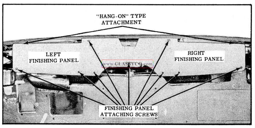
- Remove windshield lower garnish moldings and lower frame finishing panel attaching screws and re move finishing panels. (See Fig. 17-16)
1957 Oldsmobile Windshield Lower Frame Finishing Panel Installation
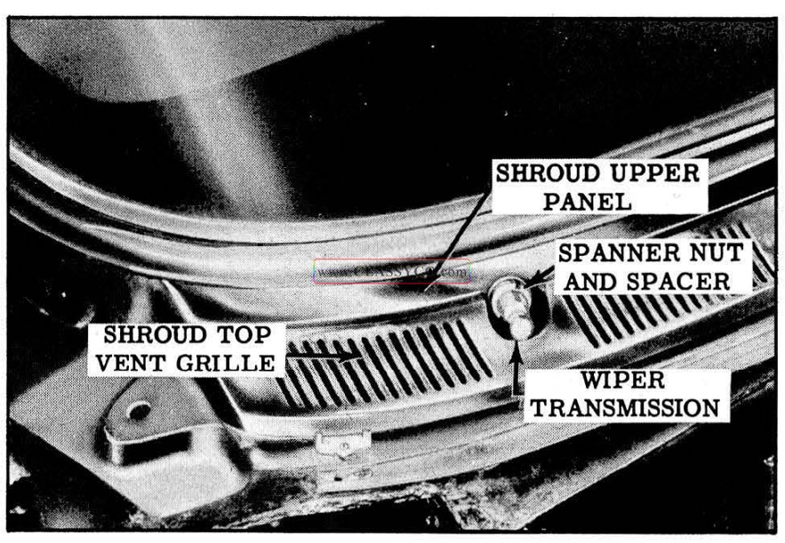
- Remove defroster nozzle attaching screws and remove defroster nozzles. (See Fig. 17-13)
- Remove wiper transmission attaching screws. Break seal between transmission gasket and body, and remove transmission. (See Fig. 17 -13)
Install
- If necessary, replace transmission gasket and arrange transmission component parts for installation. (See Fig. 17-17)
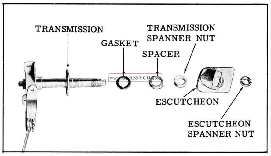
1957 Oldsmobile Windshield Wiper Transmission Component Parts
- Inside of body, check position of gasket on transmission and position transmission in body. “Start” attaching screws but do not tighten them at this time. (See Fig. 17-13)
- Outside of body, position transmission spacer and spanner nut. Check alignment of wiper transmission and tighten spanner nut with Tool 1-6592. Then, inside of body, tighten wiper transmission attaching screws. (See Fig. 17 -13)
- Install defroster nozzle. See Fig. 17-13)
- Attach transmission cables to auxiliary drive as shown.
NOTE: The “right” transmission cables attach to the two “outer” pulleys of the auxiliary drive, and the “left” transmission cables attach to the two “inner” pulleys of the auxiliary drive.
IMPORTANT: The copper colored cable ends must be installed to the copper colored pulley notches and the steel colored cable ends must be installed on the steel colored pulley notches. (See Fig. 17-13)
- Restore cable tension as required. See “Wiper Transmission Cable Adjustment”.
- Connect washer hose to escutcheon. Position escutcheon and install spanner nut with Tool J-6592. (See Fig. 17-17)
- Install wiper arm and blade assemblies and check operation of wiper transmission.
- Install windshield lower frame finishing panels and garnish moldings. (See Fig. 17-16)
WINDSHIELD WIPER TRANSMISSION CABLE ADJUSTMENT
The transmission cables are tensioned by “spring-loaded” pulleys. When the end of transmission shaft is pushed “in ” as shown in the illustration, the spring-loaded pulleys unlock and tension the cables.
To obtain slack in the wiper transmission cables, proceed as follows:
- Push “in ” base of wiper arm where arm fits over transmission shaft to unlock spring loaded pulleys.
If wiper arm has been removed, push in end of transmission.
- While pulleys are unlocked, have helper inside of car pull cable to obtain slack. When sufficient slack is obtained, release end of transmission shaft to lock cables in slack position.
- To restore tension in cables, push “in” end of transmission shaft. Repeat operation on opposite transmission.
NOTE: Loose cables cause blade slap or overtravel at end of stroke. If this condition exists, adjust tension of cables as outlined in step 3.
INSTRUMENT PANEL ASSEMBLY
The newly designed instrument panel assembly is of welded construction and is an integral part of the front end assembly. Service access to the windshield wiper transmissions and other parts covered by the instrument panel is gained under the instrument panel. The instrument panel compartment is located at the lower center of the instrument panel. An instrument panel cover of new plastic const ruction is serviced as a one -piece unit.
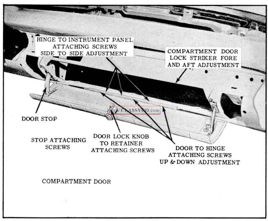
INSTRUMENT PANEL COMPARTMENT DOOR
Remove and Install
- Open door and scribe position of hinge on door.
- Remove door stop attaching screws on each side of door and disconnect door stops.
- Remove hinge to door attaching screws and remove door.
- To install, reverse removal procedure. Align door according to previously made scribe marks and tighten attaching screws.
Adjustments
- The screw holes in the compartment door side of the hinge are elongated to permit “up and down” adjustment of the door.
- The screw holes in the instrument panel side of the hinge are elongated to permit “side to-side” adjustment of the door.
- The instrument panel attaching screw holes for the lock striker are elongated to permit “fore and aft” adjustment of the top of the door. (See Fig. 17-18)
1957 Oldsmobile Instrument Panel Door
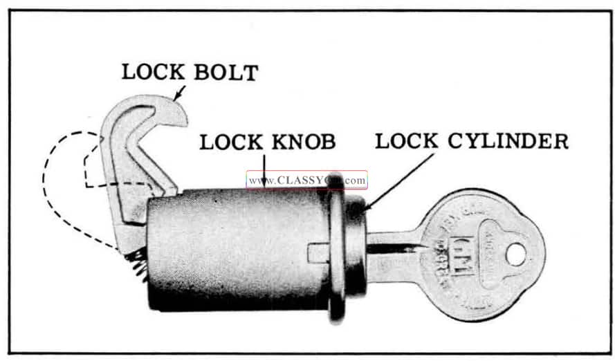
INSTRUMENT PANEL COMPARTMENT DOOR LOCK CYLINDER
Remove and Install
- Note position of lock cylinder key opening when in locked and unlocked position.
- Insert key in lock cylinder and open door.
- Hold lock bolt in rear position, tum key clockwise 90° from unlocked position, and remove cylinder with key.
- To install, reverse removal procedure. (See Fig. 17-19)
1957 Oldsmobile Lock Cylinder
INSTRUMENT PANEL COMPARTMENT DOOR LOCK KNOB
Remove and Install
- Open door and remove door lock knob to retainer attaching screw.
- Remove lock knob retainer and lock knob.
- To install, reverse removal procedure.
INSTRUMENT PANEL PAD
The instrument panel pad of new plastic construction is serviced as a one-piece unit. The pad is secured to the instrument panel by trim cement.
Remove
- Cover front seat.
- Remove windshield side and lower garnish moldings to gain access to side cementing surfaces.
- Remove or loosen instrument panel parts, such as instrument cluster, radio controls, windshield wiper control, and finishing moldings, to gain access to rear cementing surfaces of pad. If power windows are used, remove power window control switches from sides of instrument panel. (See Fig. 17-21)
1957 Oldsmobile Control Switch Attachment
- Carefully note alignment of pad to instrument panel. Then detach pad from cemented surfaces of instrument panel and lift pad from instrument panel.
Install
- Clean and dry cementing surfaces of instrument panel.
- Apply trim cement to cementing edges of pad and corresponding surfaces of instrument panel. Allow cement to dry for several minutes.
- Carefully center and position pad on instrument panel. Be especially careful to align rear roll of pad with roll of instrument panel. Then press rear cementing surfaces together to obtain a good bond.
- Remove all “fullness” and “draws” from pad by pulling material forward and downward and press cemented surfaces together at front of instrument panel to obtain a good bond. (See Fig. 17-20)
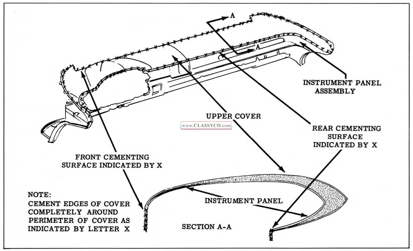
1957 Oldsmobile Instrument Panel Upper Cover Installation
- Install previously removed instrument panel parts and clean up.
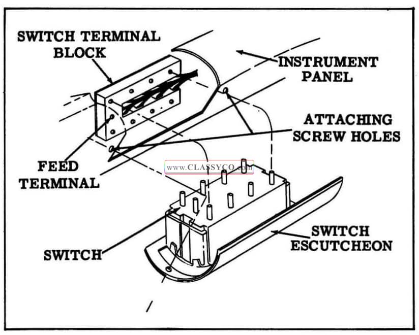
DOOR WINDOW CONTROL SWITCH
On styles with power windows, the front door window control switches are located at the outer ends of the instrument panel.
Remove and Install
- Remove attaching screws from switch escutcheon. (See Fig. 17-21)
- Move control switch and escutcheon from instrument panel sufficiently to gain access to switch terminal block.
- Disconnect terminal block and remove control switch and escutcheon as an assembly.
- To remove switch from escutcheon, depress clips at sides of switch and remove switch.
- To install, reverse removal procedure and check operation of switch.
NOTE: The master control switch feed stud should be toward rear of car when in stalled.
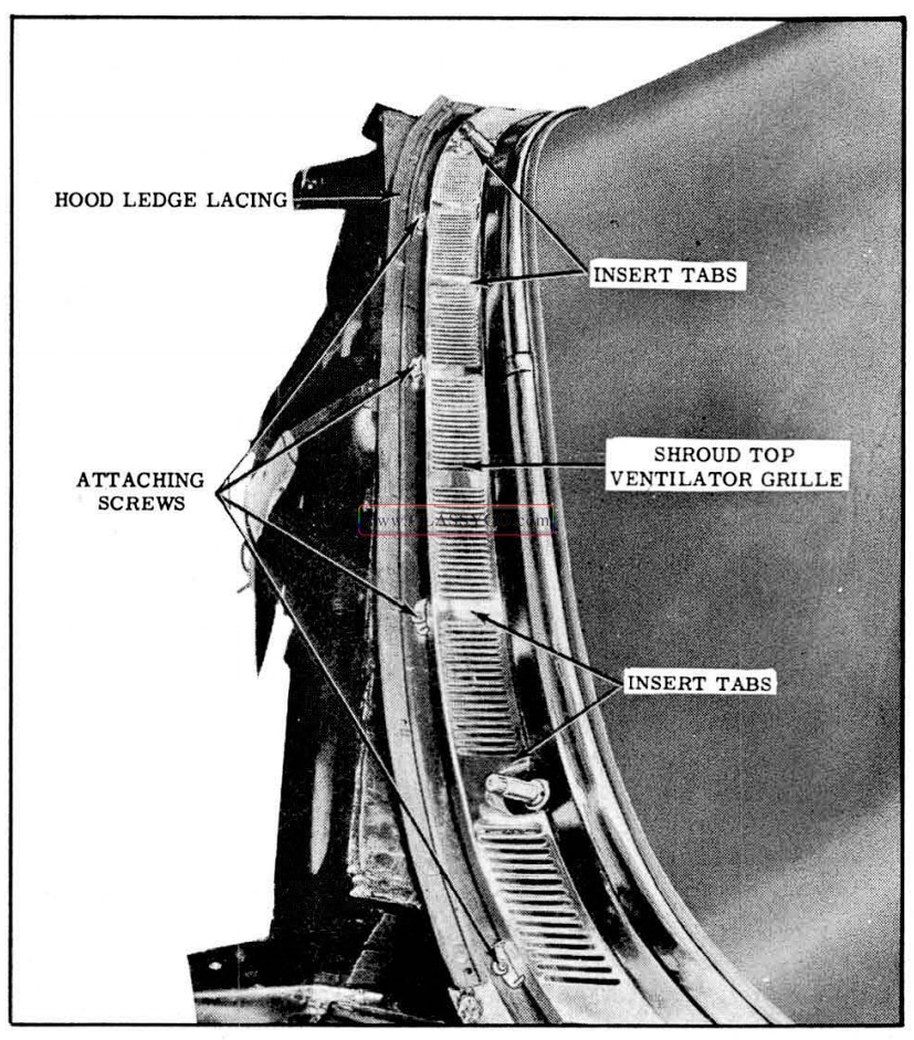
SHROUD VENTILATING GRILL ASSEMBLY
The shroud top vent grille is of one-piece construction. The grille is secured to the body at the rear edge by means of integral insert tabs and along the front edge by means of attaching screws.
Remove and Install
- Remove wiper arm and blade assemblies.
- Remove both wiper transmission escutcheon spanner nuts with Tool J-6592 and remove escutcheons. Disconnect washer hoses to re move escutcheons. Tape hoses to body to facilitate installation.
- Raise hood and remove grille attaching screws along front edge.
- To re move grille, slide grille forward to disengage integral retaining tabs, raise front edge and remove.
- To install, reverse removal procedure. (See Fig. 17 -22)
1957 Oldsmobile Ventilator Grille Assembly
FRONT AND REAR DOORS
Several new changes have been incorporated in the design of the front and rear door hardware parts on the 1957 styles. Some of these parts, such as window frames on the 2 door sedans and 4 door sedans, and the door inner panel water
deflector, are new in design and require new service methods. The side roof rail weatherstrip on the 4 door holiday bodies and the front door weatherstrip on the 4 door sedan bodies are also of a new design, requiring new service methods.
The door section is divided into the following parts:
a. Service operations which are the same or similar for both front and rear doors.
b. Service operation s for the front door.
c. Service operations for the rear door.
FRONT AND REAR DOOR INSIDE HANDLES
Remove and Install
- Depress door trim assembly at handle. Insert spring removing tool between handle and bearing plate and remove handle retaining spring; then, remove handle and bearing plate.
- To install inside handle, first install retaining spring to handle; then, position bearing plate and handle on regulator spindle and push handle until spring is engaged.
NOTE: Install handle at same angle as handle on opposite door. Window or ventilator should be in closed position when checking angle of handle.
FRONT AND REAR DOOR BELT FINISHING MOLDINGS
Remove and Install
- Remove door inside locking rod knob.
- Remove finishing screw from both ends of molding and remove molding from door.
- To install, position inside locking rod through molding and position finishing molding on door; then reverse removal procedure.
FRONT AND REAR ARM RESTS-(AII 88 Models; S88 2 Door Sedan and 4 Door Sedan)
All the above mentioned styles use applied (removable) arm rests. The remaining styles incorporate the use of built-in arm rests.
Remove and Install
- On underside of arm rest, remove 2 screws securing arm rest to arm rest support on door inner panel and remove arm rest.
- To install, reverse removal procedure.
FRONT DOOR TRIM ASSEMBLIES (All 88 Models; S88 2 Door Sedan, 4 Door Sedan; 98 4 Door Sedan)
The door trim assembly is attached to the door inner panel with individual spring-type retaining clips. To prevent damaging the door trim assembly during removal, a door trim assembly removal tool should be used.
1957 Oldsmobile Trim Pad – Retaining Clip
Remove and Install
- Remove door belt finishing molding and inside handles.
- On styles with built-in type arm rest, remove 2 screws from arm rest finishing cup. On other styles remove door arm rest.
- Remove 1 screw at both lower corners of trim assembly.
- With clean rubber mallet tap trim assembly along front and rear edges to free trim assembly retaining clips in slots.
- Insert door trim assembly remover tool between door trim assembly and water deflector until handle of tool contacts door trim foundation.
NOTE: Exercise care so as not to disturb water deflector. Then position tool to engage cut-out in tool with edge of clip and pry clip and trim assembly away from door inner panel.
CAUTION: The door trim assembly remover tool must be engaged with clip to prevent damage to trim assembly as there is no metal strip along the edge of the trim assembly.
- On doors equipped with electrically -operated window regulators, disconnect terminal block from switch assembly by carefully pulling block to disengage it from switch terminal post.
- Lift trim assembly upward to disengage trim assembly from retaining tabs and long metal retainer along lower edge of door inner panel.
- To install, reverse removal procedure. On doors equipped with electrically-operated window regulators, check operation of switch after connecting terminal block.
NOTE: Make sure that tension springs are reinstalled over window regulator and door handle spindles and that trim assembly is engaged with tabs and long metal retainer.
FRONT DOOR TRIM ASSEMBLY-(S88, 98, 4 Door Holidays, Holiday Coupes and Convertibles) AND REAR DOOR TRIM ASSEMBLY- (All Four Door Styles)
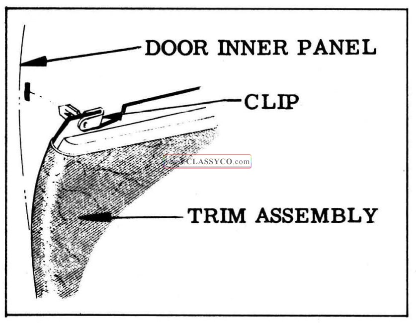
The door trim assembly is secured to the door inner panel by a nailing strip along the front and rear edge of the trim assembly, by a trim retainer along the bottom of the door, and by 2 retaining tabs on the door inner panel.
Remove and Install
- Remove door inside handle(s), bearing plate(s), and door belt finishing molding.
- On styles with applied arm rest, remove arm rest. On styles with built-in arm rest, remove 2 screws from recess hole in arm rest.
NOTE: On rear doors of S88 Holiday Sedan style, after removing door arm rest, remove 2 screws securing arm rest hanger plate and remove plate.
- Remove screws from lower corners of trim assembly.
- With a lean mallet, tap trim assembly along front and rear edges to free trim assembly nails in retainer slots.
- Place a suitable flat-bladed tool between water deflector and door trim assembly and carefully loosen front and rear edges of door trim assembly from door inner panel.
NOTE: Exercise extreme care so as not to disturb water deflector.
- Lift trim assembly upward to disengage it from retaining tabs and metal retainer which is located along lower edge of door inner panel.
- On doors equipped with electrically-powered window regulators, carefully pull terminal block from switch terminals, then remove trim assembly.
- To install reverse removal procedure.
NOTE: Make certain tension springs are reinstalled over door handle spindles where required and that trim assembly is engaged with retainer tabs and metal retainer before tapping in nail strips at front and rear edges of trim assembly. If during removal of trim assembly any retaining nails are broken off, they can be replaced with door trim assembly nailing strip replacement tabs which are avail able as a service part.
FRONT DOOR WINDOW ELECTRIC CONTROL SWITCH
Both the right and left front door window control switches are located at the outer ends of the upper section of the instrument panel. The switch assembly is secured to the instrument panel by 2 screws.
Remove and Install
- Remove 2 screws securing switch assembly to instrument panel.
- With switch assembly detached from instrument panel disconnect terminal block from switch assembly by carefully pulling switch block from switch terminals.
- To remove switch from escutcheon, depress clips at sides of switch with a pointed tool inserted through holes at sides of escutcheon.
- To install, reverse removal procedure.
NOTE: The feed stud of the master control switch should be toward the rear of the body when installed in instrument panel. Check operation of switch before installing assembly to instrument panel.
REAR DOOR WINDOW ELECTRIC CONTROL SWITCH
Remove and Install
- Remove door belt finishing molding and door inside handles.
- Loosen upper portion of trim assembly sufficiently to disconnect terminal block from switch assembly by pulling block from switch terminals.
- Carefully push switch assembly from trim assembly to release switch from retainer.
NOTE: In some instances it may be necessary to pry open retainer tabs to release switch.
- To remove switch from escutcheon depress clips at sides of switch with pointed tool inserted through holes in sides of escutcheon.
- To install, reverse removal procedure. Check operation of switch before completing installation of parts.
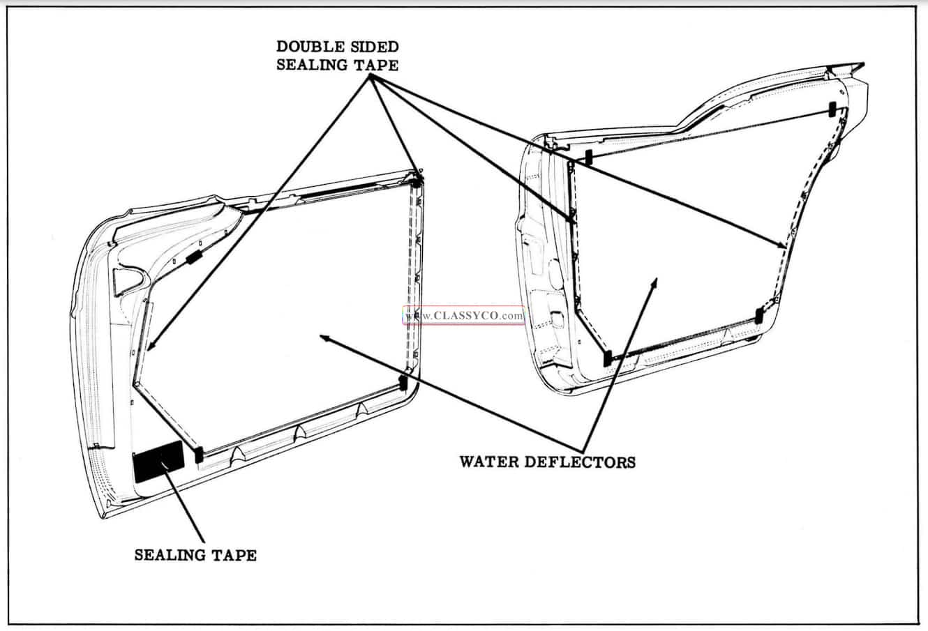
FRONT AND REAR DOOR WATER DEFLECTORS
A door water deflector consisting of a water proof paper secured to the door inner panel by an elastic double sided sealing tape is provided on the doors of all styles. The deflector which covers the complete door inner panel fits into a slot along the bottom of the door inner panel and deflects water into the bottom of the door where it can drain out the door bottom drain holes. Whenever any work is performed on a door where the water deflector has been disturbed, the deflector must be properly sealed and attached to the inner panel as specified in the following procedures.
Remove
- Remove door belt finishing molding.
- Remove door trim assembly.
- Remove trim assembly retainer tabs and door arm rest hanger plates where present.
- Carefully detach water deflector from door inner panel. Use caution that dirt or foreign matter does not get on exposed surface of tape and destroy adhesive qualities of tape.
Install
- Prior to installing water deflector, make certain surfaces of inner panel or water deflector contacted by sealing tape is free of any foreign material to insure a satisfactory seal.
NOTE: If adhesive quality of sealing tape has been damaged, cover affected area with an additional strip of tape or weatherstrip cement to insure a proper weatherseal.
- On front doors apply waterproof body tape over the lower hinge access hole. (See Fig. 17-24) On rear doors apply sealer over trim assembly lower front corner retaining slot. (See Fig. 17-24)
- Inspect water deflector and where necessary repair any tears or holes with waterproof body tape applied to both sides of deflector.
- Insert bottom edge of water deflector in slot across bottom of inner panel. Align holes in water deflector with regulator spindles and inside trim and hardware installation holes. When properly aligned press or roll edges of water deflector to inner panel to effect a watertight seal.
- Tape upper and lower corners of water deflector to inner panel with 2 inch strips of waterproof body tape. (See Fig. 17-24)
- Install previously removed door trim assembly retainer tabs and door arm rest hanger plate where used, then install door trim and inside hardware.
1957 Oldsmobile Door Water Deflectors
FRONT AND REAR DOOR LOCK STRIKER
Remove and Install
- With a pencil scribe position of striker on body pillar.
- Remove 3 door lock striker attaching screws and remove striker and adjusting plates from pillar.
- To install, place striker and adjusting plates within scribe marks on pillar and tighten screws.
IMPORTANT: Whenever a door has been removed and installed, or realigned, the door SHOULD NOT be closed completely until a visual check is made to determine if the lock extension will engage in the striker notch. Where required, door lock striker emergency spacers should be installed so that door can be closed and an accurate check made to determine emergency spacer requirements.
DOOR LOCK STRIKER ADJUSTMENTS
- To adjust striker “up” or “down” or “in” or “out” loosen striker plate screws and shift striker and adjusting plates as required, then tighten screws.
- DIMENSIONAL SPECIFICATIONS FOR USE OF OOOR LOCK STRIKER EMERGENCY SPACERS.
a. Door should be properly aligned before checking door spacer requirements.
b. To determine if door lock striker emergency spacers are required, apply modeling clay or body caulking compound in the door lock striker notch where the lock extension engages and then close the door to form a measurable impression in the clay or caulking compound, as shown in Fig. 17-25.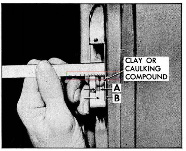
1957 Oldsmobile Checking Striker Plate
When dimension “A ” from inside face of striker teeth to center of lock extension is less than 3/16″, install emergency spacers and proper length striker attaching screws as directed below.
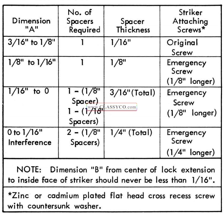
1957 Oldsmobile Lock Striker Table
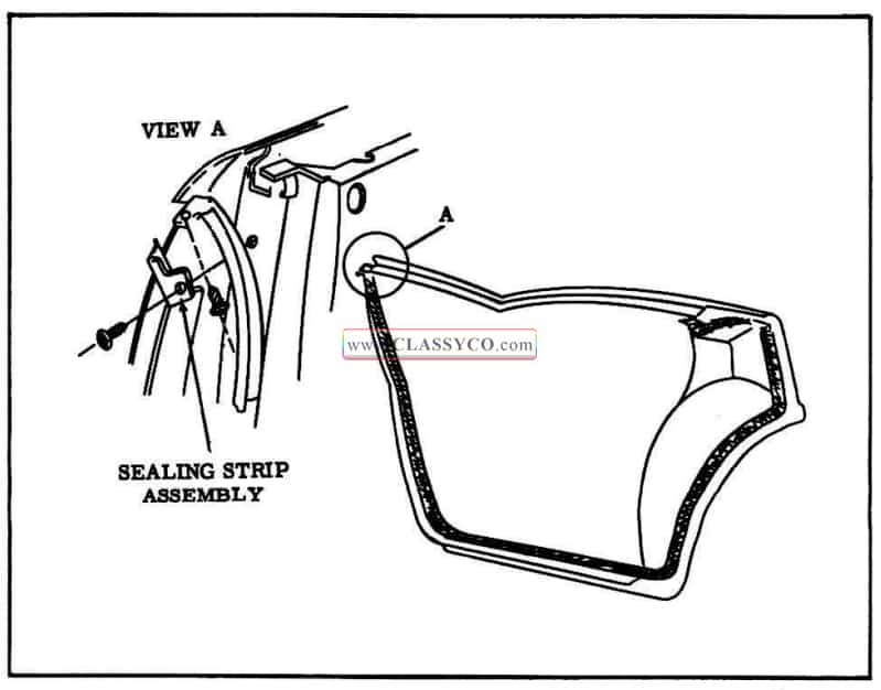
DOOR AND SIDE ROOF RAIL WEATHERSTRIPS
The door and side roof rail weatherstrips are constructed of foam rubber encased in an outer skin of hard rubber. This outer casing must not be broken if the weatherstrip is to perform its proper function since the foam rubber is water absorbant. Any small breaks or fractures that occur in the outer casing should be repaired by applying black weatherstrip cement to the affected area. If large breaks occur the weatherstrip should be replaced.
FRONT DOOR WEATHERSTRIP- (2 Door Sedans and 4 Door Sedans)
The newly designed front door weatherstrip is a continuous loop-type mechanically-retained weatherstrip with external clips formed from a wire insert within the weatherstrip. The weatherstrip is installed from the outer side of the door and then secured to the door by snapping the weatherstrip clips into holes around the perimeter of the door. In addition the weatherstrip is cemented to the door at the cove area.
Remove
- Remove the door belt finishing molding. Re move 5 screws securing front door ventilator garnish molding assembly and remove assembly.
- With a flat-bladed tool carefully break cement bond along cove area of door.
- Carefully position tip of mechanically- retained weatherstrip inserting tool, or any other suit able tool, under weatherstrip at each clip lo cation and snap clip out of hole. Then work weatherstrip over door hemming flange and remove from body.
Install
- Remove door trim assembly and inner panel water deflector.
- Check weatherstrip clips for proper contour and reform if necessary using clip reforming tool 1-5984.
- Clean off old cement from cover area of door to provide a clean cementing surface. Then apply an approved weatherstrip cement to weatherstrip attaching surface along “cove” area as indicated in section “A-A” in Figure 17-27 and to corresponding surface of weatherstrip.
- Install weatherstrip from outer side of door so that formed corners of weatherstrip are at upper corners of door.
- Starting at the top of door, install weatherstrip retaining clips around perimeter of door and secure weatherstrip at cove area. To install clips into clip holes, place “V” shaped tip of weatherstrip inserting tool on loop of clip; then push clip into hole until it snaps into position.
NOTE: Do not use excessive force or strike tool when pushing clips into holes as it may distort shape of clips, resulting in improper weatherstrip retention.
- Apply cement to joint of door inner panel and front door hinge pillar, as indicated in View D; Fig. 17-27, to prevent water from entering under weatherstrip. Clean off all excess cement.
- Working through large access hole, apply medium-bodied sealer over and around weatherstrip attaching clips along bottom of door and to lower clip at each pillar. (See Fig. 17-27)
- Install all previously removed parts.
NOTE: When installing ventilator garnish molding, slide front edge of molding over 4 door weatherstrip retaining clips; then install screws securing molding.
REAR DOOR WEATHERSTRIPS (4 Door Sedans)
The rear door weatherstrips are a one-piece mechanically-retained type with external clips formed from a wire insert extending through the length of the weatherstrip. The weatherstrips are secured to the door by snapping the weatherstrip clips into holes around the perimeter of the door. The ends of the weatherstrips are cemented together to form a “butt” joint at the bottom of the door. In addition the weatherstrip is cemented at the upper rear corner of the door at the belt line.
Remove
- Use a flat-bladed tool and carefully break cement bond at “butt” joint on bottom of door and break cement bond at upper rear corner of door at belt line.
- Use a mechanically-retained weatherstrip inserting tool, or other suitable tool, and carefully position tip of tool under weatherstrip at each clip location and snap clip out of hole.
Install
- Remove door trim assembly and inner panel water deflector.
- Check weatherstrip clips for proper contour and reform if necessary using clip reforming tool No. J-5984. (See Fig. 17-26)
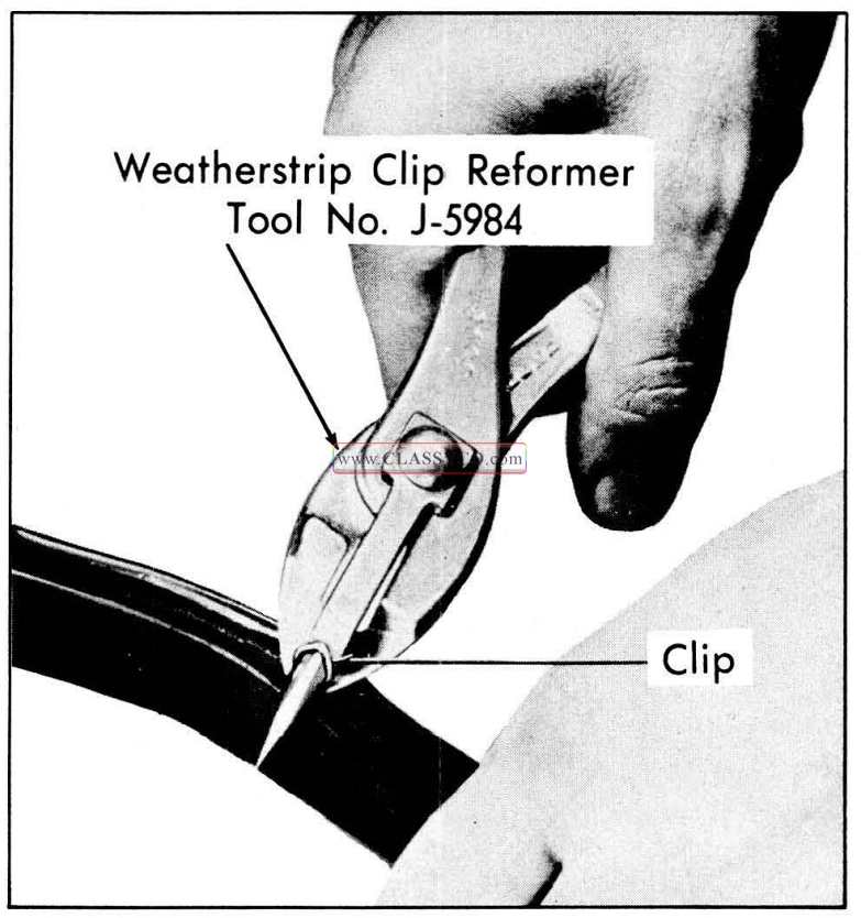
1957 Oldsmobile Reforming Weatherstrip Clip
- Clean off old cement from surfaces of door to provide a clean cementing surface for weatherstrip installation.
- Apply an approved weatherstrip cement to weatherstrip attaching surface along upper rear corner of door as indicated in Section “B-B” in Fig. 17-27 and to corresponding surface of weatherstrip.
a. Position color mark on weatherstrip between fourth and fifth holes from hinge pillar corner of door upper facing, and position formed bend of weatherstrip at upper rear corner of door at belt line.
b. Starting at formed portion of weatherstrip, install weatherstrip-retaining clips around permiter of door. To install clips into clip holes, place “V” shaped tip of weatherstrip inserting tool on loop of clip; then push clip into hole until it snaps into position.
NOTE: Do not use excessive force or strike tool when pushing clips into holes as it may distort shape of clip, resulting in improper weatherstrip retention.
- Trim off ends of weatherstrip, if necessary, and form “butt” joint between 2 center holes on bottom of door.
NOTE: Service replacement weatherstrips may be longer than required to assure a satisfactory “butt” joint. Do not cut weather strip to form “butt” joint until all clips are installed into holes around the door.
- Apply weatherstrip cement to ends of weatherstrip and to bottom of door approximately 2-1/2 inches on both sides of “butt” joint as shown in section “C-C” Fig. 17-27. Form “butt” joint with ends evenly matched to pro vide a continuous seal.
- Working through large access hole apply medium-bodied sealer over and around weather strip attaching clips along bottom of door and to lower clip on each pillar. See Section “E-E”, Fig. 17-27.
- Install all previously removed parts.
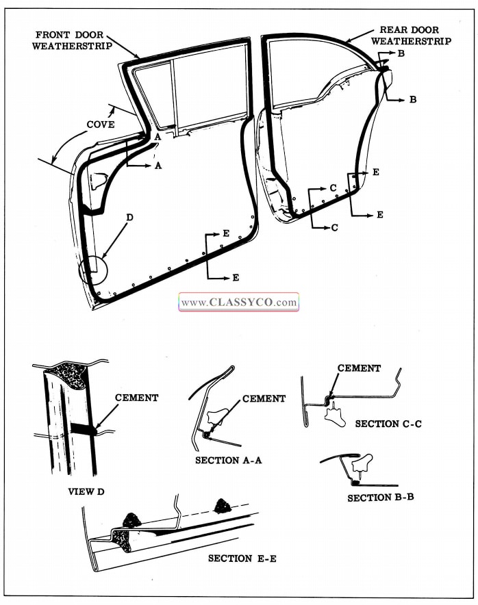
1957 Oldsmobile Door Weatherstrips
1957 Oldsmobile Door Weatherstrips 2
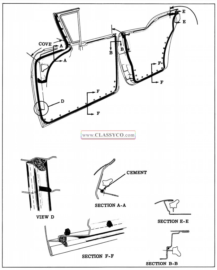
FRONT AND REAR DOOR WEATHERSTRIP5- (4 Door Holidays, Holiday Coupes and Convertibles)
The front and rear door weatherstrips are one piece weatherstrips secured to the door by a combination of integral tabs and clips. In addition, on front doors, the weatherstrip is cemented along the “cove” area and at the upper rear corner of the door. On rear doors the weatherstrip is cemented at the upper rear corner of the door. An additional weatherseal is obtained on the rear doors by the use of a rear door hinge pillar sealing strip assembly. This sealing strip is located adjacent to the end of the door weatherstrip and is secured in place by 1 screw.
Remove
- Remove door belt finishing molding.
- On front doors remove screws securing weatherstrip to ventilator frame and screw(s) securing lock pillar end of weatherstrip. On rear doors remove screws securing ends of weatherstrip to hinge pillar and lock pillar. (See Fig. 17-29)
1957 Oldsmobile Hinge Pillar Weatherstrip
- With a flat-bladed tool, carefully break cement bond at “cove” area on front doors and at upper end of lock pillar on all doors.
- Using a mechanically-retained weatherstrip inserting tool, or other suitable tool, carefully position tip of tool under weatherstrip at each clip location and snap clip out of hole. Then remove weatherstrip.
Install
- Remove door trim assembly and inner panel water deflector.
- Check weatherstrip clips for proper contour and reform, if necessary, using clip reforming tool No. J-5984. (See Fig. 17-26)
- Clean off all old cement to insure a clean cementing surface.
- Apply approved weatherstrip cement to weatherstrip attaching surfaces of door and weatherstrip.
- On front door, apply cement from point 3 inches above “cove” area completely around “cove” area as indicated in section “A-A” Fig. 17-28. Apply cement in corner of rabbet on door beginning at lock pillar end of weatherstrip and extending down ward to a point just below the second clip as shown in section “8-B”. Apply cement to joint of door inner panel and door hinge pillar panel as indicated in View “D”, Fig. 17-28, to prevent water from entering under weatherstrip. Clean off excess cement.
- On rear doors apply cement in corner of rabbet beginning at lock pillar end of weatherstrip and extending downward to a point between fourth and fifth attaching holes as shown in section “E-E”.
- Locate weatherstrip on door and install weatherstrip clips in clip holes starting at upper end of lock pillar on front doors and upper end of hinge pillar on rear doors. To install clips into clip holes, place “V” shaped tip of weatherstrip inserting tool on loop of clip; then push clip into hole until it snaps into position.
NOTE: Do not use excessive force or strike tool when pushing clips into holes as it may distort shape of clip, resulting in improper weatherstrip retention.
- Install weatherstrip tab attaching screws at ends of weatherstrip.
- Working through access hole, apply medium-bodied sealer over and around weatherstrip attaching clips as indicated in section “F -F” Fig. 17-28.
- Clean off all excess cement and install door inner panel water deflector, door trim assembly, and belt finishing molding.
FRONT DOOR HINGE PILLAR AUXILIARY WEATHERSTRIP
Remove
- With a flat-bladed tool carefully remove 3 snap-on fasteners securing weatherstrip, then break cement bond and remove weatherstrip from door pillar. (See Fig. 17-27 or 17-28)
Install
- Clean off old cement from area of hinge pillar contacted by weatherstrip.
- Apply an approved weatherstrip cement to the surface of the hinge pillar contacted by the weatherstrip and to the weatherstrip attaching surface.
- Install weatherstrip to hinge pillar, aligning snap-on clip in weatherstrip with holes in hinge pillar.
- Install snap-on clips. Firmly press or roll entire length of weatherstrip to hinge pillar to assure a complete cement bond.
- Clean off any excess cement.
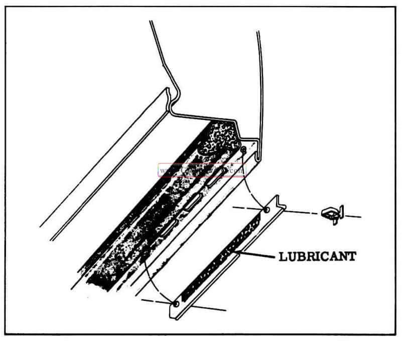
FRONT AND REAR DOOR BOTTOM DRAIN HOLE SEALING STRIPS
The 2 door bottom drain hole sealing strips are located on the bottom of each door. Each sealing strip is attached to the door inner panel by a snap-on fastener at each end of the strip. To prevent the strip from adhering to the door inner panel and blocking the drain holes, apply a sparing amount of silicone rubber lubricant on the center section of the weatherstrip as indicated in Fig. 17-30.
1957 Oldsmobile Drain Hole Sealing Strip
FRONT BODY HINGE PILLAR AUXILIARY UPPER WEATHERSTRIP (Holiday Coupes, Holiday Sedans and Convertibles)
The front body hinge pillar auxiliary weather strip is a one-piece mechanically-retained weatherstrip secured to the body hinge pillar by 4 clips. Either of 2 types of clips may be used:
a. A loop-type clip may be formed from a wire insert extending through the entire length of the weatherstrip. This type of clip requires the use of the mechanically retained weatherstrip inserting tool to remove and install the weatherstrip.
b. Individual rectangular clips, equally spaced along the weatherstrip may be used. This type of clip requires the use of long nose pliers, or other suitable tool, to remove and install the weatherstrip.
NOTE: Before removing the weather strip check the weatherstrip to determine which type of clip is used. If a wire insert can be felt within the weatherstrip the mechanically-retained inserting tool must be used.
Remove and Install
- To remove and install weatherstrip with looptype clips:
a. Carefully position tip of mechanically retained weatherstrip inserting tool, or any other suitable tool, under weatherstrip at each clip location and snap clip out of hole. Then remove weatherstrip.
b. Position weatherstrip to hinge pillar and install clips into holes with mechanically retained weatherstrip inserting tool. To install clips in holes place “V” shaped tip of tool on loop and push clip into hole.
NOTE: Do not use excessive force or strike tool when pushing clips into holes as it may distort shape of clips and cause improper weatherstrip retention.
- To remove and install weatherstrip with rectangular-type clips:
a. Position long nose pliers, or other suitable tool, under weatherstrip at each clip location and squeeze clip to disengage barbed part of clip and remove clip from hole.
b. Position weatherstrip to hinge pillar and apply thumb pressure at each clip location to install clip.
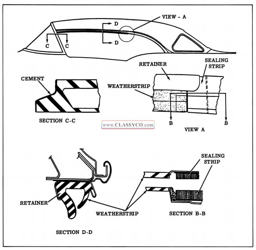
SIDE ROOF RAIL WEATHERSTRIP (4 Door Holidays)
The newly designed side roof rail weatherstrip for 4 Door Holidays is a one-piece mechanically retained type with external clips formed from a wire insert extending through the length of the weatherstrip. In addition to the clips the weather strip is secured by a side roof rail weatherstrip retainer which is attached to the side roof rail by screws.
IMPORTANT: At the center of the weather strip, a section (approximately 10 inches long) is provided with a reinforced outer skin to pre vent excessive wear from the rear door window upper frame during closing and opening of the door. This reinforced section of the weatherstrip should be correctly located to properly perform its function.
Remove
- With a flat-bladed tool, carefully break cement bond between front end of weatherstrip and body windshield pillar.
- Disengage weatherstrip from outer flange of retainer. Then carefully position tip of mechanically-retained weatherstrip inserting tool, or any other suitable tool, under weather strip at each clip location and snap clip out of hole.
Install
- Check weatherstrip clips for proper contour and reform if necessary using weatherstrip reforming tool J-5984. (See Fig. 17-26)
- Position weatherstrip to retainer at side roof rail so that front end “butts” against body windshield pillar and reinforced section (ap proximately 10 inches long) is over front edge of the rear door window upper frame. Install weatherstrip clips into clip holes with mechanically-retained weatherstrip inserting tool. To install clips into holes, place “V” shaped tip of tool on loop of clip, then push clip into hole until it snaps into position.
NOTE: Do not use excessive force or strike tool when pushing clips into holes, as it may distort shape of clips, resulting in improper weatherstrip retention.
- Apply weatherstrip cement to front end of weatherstrip and cement it to body windshield pillar.
- Engage weatherstrip in both inner and outer flanges of retainer along entire length of retainer.
- With doors and windows closed, front and rear door window upper frames should make an even, continuous contact with the side roof rail weatherstrip. If necessary, adjust ventilator and/or front and rear door windows to obtain proper weatherstrip contact.
- Lubricate side roof rail weatherstrip as outlined in “LUBRICATION” section.
SIDE ROOF RAIL WEATHERSTRIP ADJUSTMENTS
The attaching holes in the side roof rail weatherstrip retainer are elongated, allowing “in” and “out” adjustment of the side roof rail weatherstrip; how ever, the amount of adjustment is small, and is not intended to correct for improper ventilator or door window alignment. The retainer attaching screws are located under the weatherstrip, necessitating removal of the weatherstrip to make an adjustment.
IMPORTANT: Before attempting to adjust the side roof rail weatherstrip, first check that the ventilator and front and rear door windows are properly aligned and, where necessary, adjust for proper alignment as directed under “ADJUSTMENTS” in the Ventilator, Front Door Window and Rear Door Window service procedures.
- To adjust side roof rail weatherstrip “in ” or “out” first determine and mark retainer at area or areas to be adjusted; then remove side roof rail weatherstrip.
- Loosen weatherstrip retainer attaching screws slightly in area to be adjusted; then place wooden block or suitable tool against the inner or outer flange of the retainer and tap tool lightly to properly position retainer.
- Tighten retainer attaching screws and reinstall weatherstrip.
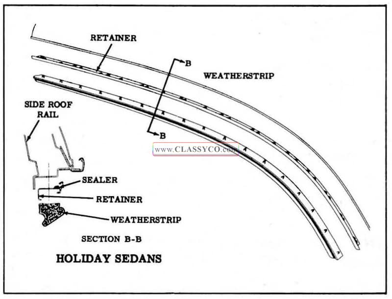
SIDE ROOF RAIL WEATHERSTRIP ROAINER (4 Door Holidays)
The side roof rail weatherstrip retainer is a channel-type molding secured to the side roof rail by 12 screws. The retainer may be adjusted “in” or “out”; however, the amount of adjustment is small, and is not intended to correct for improper ventilator or door window alignment. It is important that the ventilator and the front and rear door windows are checked and, if necessary, aligned for proper contact with the side roof rail weatherstrip prior to installation of the retainer and weatherstrip.
Remove
- Remove side roof rail weatherstrip from retainer.
- Remove screws securing side roof rail weatherstrip retainer to side roof rail and remove retainer.
NOTE: Exercise care during removal so as not to bend molding, as this may affect proper weatherseal after installation.
Install
- Remove sealer from side roof rail and retainer to insure a clean sealing surface.
- Apply sealer to top of retainer just outboard of attaching holes along entire length of retainer. (See Fig. 17 -31)
- Position weatherstrip retainer to side roof rail and secure in place by installing screws at front, center, and rear of retainer. Then install remaining screws.
- Install side roof rail weatherstrip.
1957 Oldsmobile Side Roof Rail Weatherstrip
SIDE ROOF RAIL WEATHERSTRIP(88 Holiday Coupe)
The newly designed side roof rail weatherstrip is secured to the side roof rail by a channel-type retainer. Holes are provided in the weatherstrip and retainer to provide adjustment without removing the weatherstrip.
Remove
Due to accessibility of weatherstrip retainer attaching screws, the weatherstrip may be removed in either of 2 ways.
a. Weatherstrip may be removed directly from body.
b. Weatherstrip and retainer assembly may first be removed and then weatherstrip removed from retainer.
The following procedure covers removal of the weatherstrip directly from the body.
- With a flat-bladed tool, carefully break cement bond between front end of weatherstrip and windshield pillar, and cement bond between rear end of weatherstrip and side roof rail rear quarter sealing strip located within retainer.
- With a flat-bladed tool, carefully disengage outboard lip of weatherstrip from retainer and remove weatherstrip.
Install
- Clean off cementing surface on windshield pillar to provide a smooth surface.
- Apply an approved weatherstrip cement to both ends of weatherstrip and install weatherstrip to retainer. To facilitate installation, engage outboard edge of weatherstrip to retainer just prior to engaging inboard edge.
NOTE: Make certain each lip of weatherstrip at rear end of weatherstrip forms a “butt” joint with each lip of sealing strip as shown in section “B-B” Fig. 17-32.
- If installing a new weatherstrip, make certain holes in weatherstrip are aligned with retainer attaching screws. Carefully trim front end of weatherstrip flush against body windshield pillar and rear end flush against sealing strip to insure proper weatherseal and neat appearance.
1957 Oldsmobile Side Roof Rail Weatherstrip (2)
SIDE ROOF RAIL WEATHERSTRIP ADJUSTMENTS
The attaching holes in the side roof rail weatherstrip retainer are elongated allowing “in” and “out” adjustment of the side roof rail weatherstrip; however, the amount of adjustment is small, and is not intended to correct for improper ventilator or door window alignment. The side roof rail weatherstrip need not be removed to adjust the retainer.
IMPORTANT: Before attempting to adjust the side roof rail weatherstrip first check that the ventilator and door window are properly aligned and, where necessary, adjust for proper alignment as directed under “ADJUSTMENTS” in the Ventilator, and Door Window service procedures.
- To adjust side roof rail weatherstrip “in” or “out” first determine and mark retainer at area, or areas, to be adjusted.
- Loosen retainer attaching screws slightly in areas to be adjusted; then adjust retainer in or out as required.
NOTE: Make adjustments along sufficient length of the retainer to insure a continuous seal.
- Tighten retainer attaching screws.
SIDE ROOF RAIL WEATHERSTRIP RETAINER
Remove
- Remove side roof rail weatherstrip from retainer.
NOTE: Due to accessibility of retainer attaching screws, the weatherstrip and retainer may first be removed from body and then weatherstrip removed from retainer.
- Remove side roof rail rear quarter sealing strip front attaching screw.
- Remove screws securing retainer to side roof rail; then carefully detach rear end of retainer from sealing strip and remove retainer.
Install
- Clean off sealing surfaces of retainer and side roof rail to insure a smooth surface.
- Apply a continuous 3/16″ bead of caulking compound along top of retainer just outboard of attaching holes and along front of retainer.
- Position rear end of retainer over forward end of sealing strip, then position front end of retainer against body windshield pillar and in stall retainer.
NOTE: Seal forward end of sealing strip to side roof rail to insure a proper weather seal.
- Install side roof rail weatherstrip.
- With doors and windows closed, the door window upper frame and ventilator frame should make an even, continuous contact with the side roof rail weatherstrip. If necessary, adjust ventilator and/or door window to obtain proper weatherstrip contact.
SIDE ROOF RAIL MECHANICAL SEALING STRIP-(S88, 98 Holiday Coupes)
Remove
- Remove 1 screw securing front end weather strip and 1 screw securing rear end weather strip. With a flat-bladed tool, carefully break cement bond securing each weatherstrip and remove weatherstrips.
- Remove remaining sealing strip attaching screws and remove strip with attached gasket from body.
- If necessary, remove gasket from sealing strip.
Install
- Clean original caulking compound from side roof rail and gasket, and clean front and rear weatherstrip cementing surfaces. If gasket was detached, remove the double coated adhesive tape from sealing strip.
NOTE: The tape is used only to facilitate production installation of the gasket to sealing strip.
- Tape outer sealing strip to inner strip so that outer strip is in closed position for installation of rubber gasket.
- Assemble gasket to sealing strip with an ap proved weatherstrip cement. Carefully follow the manufacturer’s directions for cement ap plication, and observe the following precautions:
a. Do not apply cement to lip (awning) of gasket.
b. Do not apply cement so that it could enter the hinge portion or attaching holes of sealing strip.
c. Assemble gasket to sealing strip so that lip (awning) is over outside radius of the hinge throughout its entire length.
d. Cement gasket evenly to sealing strip. - Apply a continuous 3/16″ ribbon of caulking compound along entire length of gasket just outboard of attaching holes and along front edge of gasket as indicated by “2” in Fig. 17-33. Compound should compress easily so that it does not interfere with installation and operation of sealing strip.
- Position mechanical sealing strip to side roof rail and secure in place by installing all but the end attaching screws.
- Apply an approved weatherstrip cement to top and end contacting surfaces of front and rear weatherstrips as indicated by “3” in Fig. 17-33, and install weatherstrips.
- Align sealing strip with top of door window and ventilator, and tighten screws uniformly. Wipe off excess sealer.
1957 Oldsmobile Side Roof Rail Mechanical Sealing Strip
Adjustments
The attaching holes in the side roof rail mechanical sealing strip assembly are elongated, allowing “in” and “out” adjustment of the sealing strip; however, the amount of adjustment is small, and is not intended to correct for improper ventilator or door alignment. The purpose of this adjustment is to obtain the proper closing effect of the sealing strip.
IMPORTANT: Before attempting to adjust the side roof rail mechanical sealing strip assembly, first check that the ventilator and door window are properly aligned and, where necessary, adjust for proper alignment as directed under “ADJUST MENTS” in the Ventilator and Door Window serv ice procedures.
- Loosen sealing strip attaching screws.
- Adjust strip in or out as required; then tighten screws.
Lubrication
In cases where the action of the outer sealing strip is sluggish due to friction with lip (awning) of the rubber gasket, apply a sparing amount of a silicone rubber lubricant along the entire length of the exposed inner lip of the gasket, as indicated at “1”, in Fig. 17-33.
FRONT DOOR ASSEMBLY
The front door hinges are the swing-out type with an integral check and hold-open, similar to past models. At both the upper and lower front door hinges 1 of the hinge to front body hinge pillar attaching bolts is installed from the front of the front body pillar, necessitating detachment or removal of chassis parts to gain access to the bolts for removal of the hinges from the body. However, these bolts have a hexagon end and can be loosened from inside the hinge box, thereby facilitating adjustment of the door hinges at the body pillar WITHOUT removal of chassis parts. The 2 Door and 4 Door Sedans have a removable door window frame. All doors are equipped with a waterproof door inner panel water deflector which is sealed to door inner panel with a double sided sealing tape. The bottom edge of the deflector fits into a slot along the bottom of the door inner panel thereby deflecting any water into the bottom of the door, where it can drain out the door bottom drain holes. Door lock levers are provided with redesigned spring clips which will facilitate easier detachment of the connecting rods.
Remove and Install
- Place suitable protective covering over front fender at door opening to protect finish.
- Remove door trim assembly. Detach edge of door inner panel water deflector sufficiently to gain access to upper hinge strap bolts. (See Fig. 17-34)
- On doors equipped with electrically operated windows, proceed as follows:
a. Remove door inner panel water deflector. b. Remove screws securing electrical conduit to door hinge pillar, then bend down conduit tabs and remove conduit from wire harness. (See Fig. 17 -34)
b. Disconnect harness connector from studs on regulator motor and detach wire harness clips or harness from clips as required to remove harness from between door panels through opening in door hinge pillar.
c. Scribe hinge strap locations on door. With door properly supported, remove hinge strap bolts securing door to hinge straps. (See Fig. 17-34)
1957 Oldsmobile Front Door Hinges
- Remove door assembly from body.
- To install door assembly reverse removal procedure, aligning hinges within scribe marks before tightening hinge bolts.
NOTE: As an anti-squeak precaution, before installation of door, coat attaching surface of hinges with heavy-bodied sealer, as indicated in Fig. 17-35.
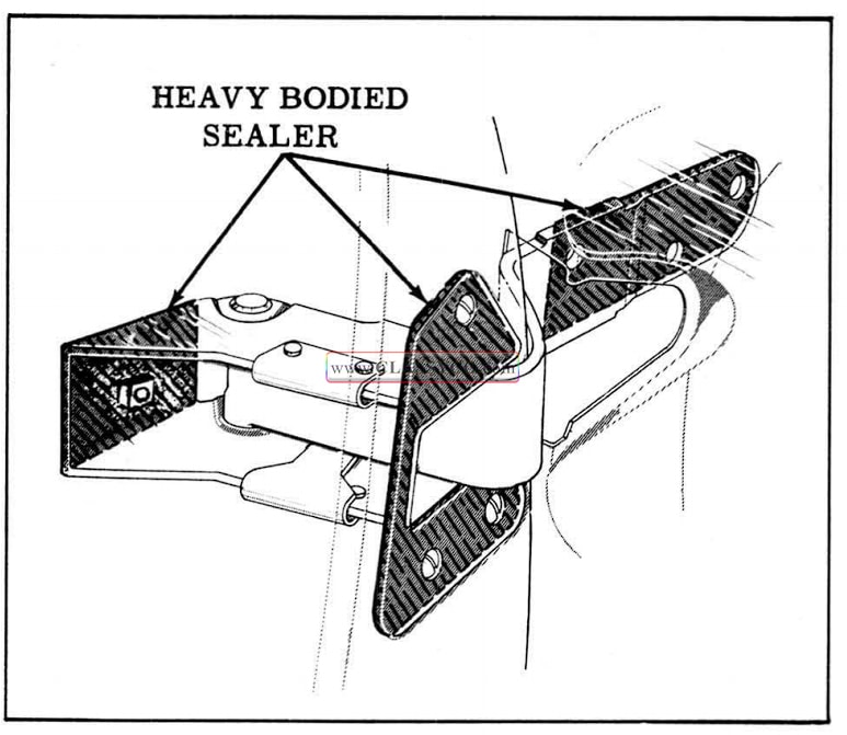
1957 Oldsmobile Front Door Hinge Sealing and Anti-Squeak
FRONT DOOR ADJUSTMENTS
Door adjustments are provided through the use of floating cage nuts and anchor plates in the door and adjacent hinge pillar. The front doors may be adjusted fore or aft at the door hinge straps, and in or out at the front body hinge pillar; up or down adjustments may be made at both the door hinge strap and front body hinge pillar.
IMPORTANT: After performing any door adjustments the door lock extension-to-striker engagement should be checked and, if necessary, adjust, as described under “DOOR LOCK STRIKER ADJUSTMENTS”. In addition the front door ventilator and window should be checked for proper alignment with the side roof rail mechanical sealing strip or the side roof rail weatherstrip and adjusted where required.
- To adjust the front doors fore or aft and/or up or down proceed as follows:
a. Remove door trim assembly. Remove tape covering lower hinge access hole. Detach upper front edge of door inner panel water deflector sufficiently to gain access to upper hinge strap bolts. (See Fig. 17 -34)
b. Remove door lock striker from body pillar to allow the door to hang freely on the hinges.
c. Scribe location of hinge straps on door.
d. Loosen hinge strap bolts (See Fig. 17-34) and shift door to desired position, then retighten bolts.
NOTE: Additional up or down adjustment may be obtained at the front body hinge pillar.
e. Apply waterproof body tape over lower hinge access hole. Reseal upper front edge of inner panel water deflector, then install previously removed door trim and inside hardware. - To adjust the front doors in or out and /or up or down at the body front hinge pillar, proceed as follows:
a. Scribe location of hinge on body front hinge pillar.
b. Inside hinge box, loosen (turn clockwise) hinge attaching bolt installed from front of body hinge pillar. (See Fig. 17 -34)
c. Loosen hinge attaching bolts at face of hinge pillar. (See Fig. 17 -34)
Shift door to desired position; tighten bolts at face of pillar then tighten (turn counterclockwise) bolt inside hinge box.
FRONT DOOR VENTILATOR AND VENTILATOR REGULATOR
The front door ventilator, ventilator frame and ventilator regulator are new in design and method of attachment. The ventilator, ventilator frame, and ventilator regulator may be removed from the door as a complete unit; however, the service methods described in this section cover procedures for the separate assemblies.
FRONT DOOR VENTILATOR GARNISH MOLDING-(2 Door and 4 Door Sedans)
Remove and Install
- Lower door window and remove door belt finishing molding.
- Remove 3 ventilator garnish molding attaching screws at front of molding and 1 screw at top and bottom of molding.
- Carefully remove garnish molding from under door weatherstrip and remove from door.
- To install front door ventilator garnish molding, reverse removal procedure.
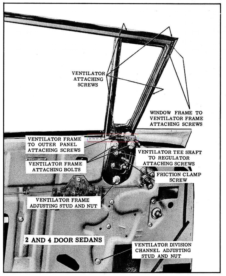
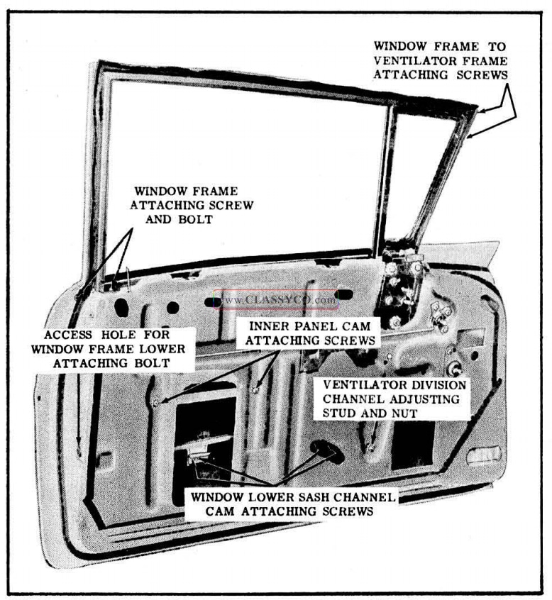
FRONT DOOR VENTILATOR (2 Door and 4 Door Sedans)
Remove and Install
- Lower door window. Remove door trim assembly, ventilator garnish molding, and inner panel water deflector.
- Remove ventilator tee shaft to regulator shaft attaching screw and ventilator regulator attaching screws. (See Fig. 17-36) Remove ventilator regulator from door through front access hole.
- Remove ventilator division channel adjusting stud and nut. (See Fig. 17-36)
- Remove ventilator attaching screws at locations indicated in Fig. 17-36.
- Lower ventilator sufficiently to tilt inward, then lift ventilator upward and remove from door.
- To install front door ventilator, reverse removal procedure. Adjust ventilator assembly as outlined under “FRONT DOOR VENTILA TOR ADJUSTMENTS”.
1957 Oldsmobile Front Door Ventilator, Ventilator Frame, and Ventilator Regulator
FRONT DOOR VENTILATOR FRAME (2 Door and 4 Door Sedans)
Remove and Install
- Remove front door ventilator assembly as described under “FRONT DOOR VENTILATOR ASSEMBLY – REMOVE AND INSTALL “.
- Detach door weatherstrip from ventilator area.
- Remove window frame to ventilator frame attaching screws at upper front of ventilator. (See Fig. 17-36)
- Remove ventilator frame to outer panel attaching screw, ventilator frame adjusting stud and nut and ventilator frame attaching bolts. (See Fig. 17 -36) Then remove ventilator frame from door.
- To install front door ventilator frame, reverse removal procedure. Adjust ventilator assembly as outlined under “FRONT DOOR VENTILATOR ADJUSTMENTS”.
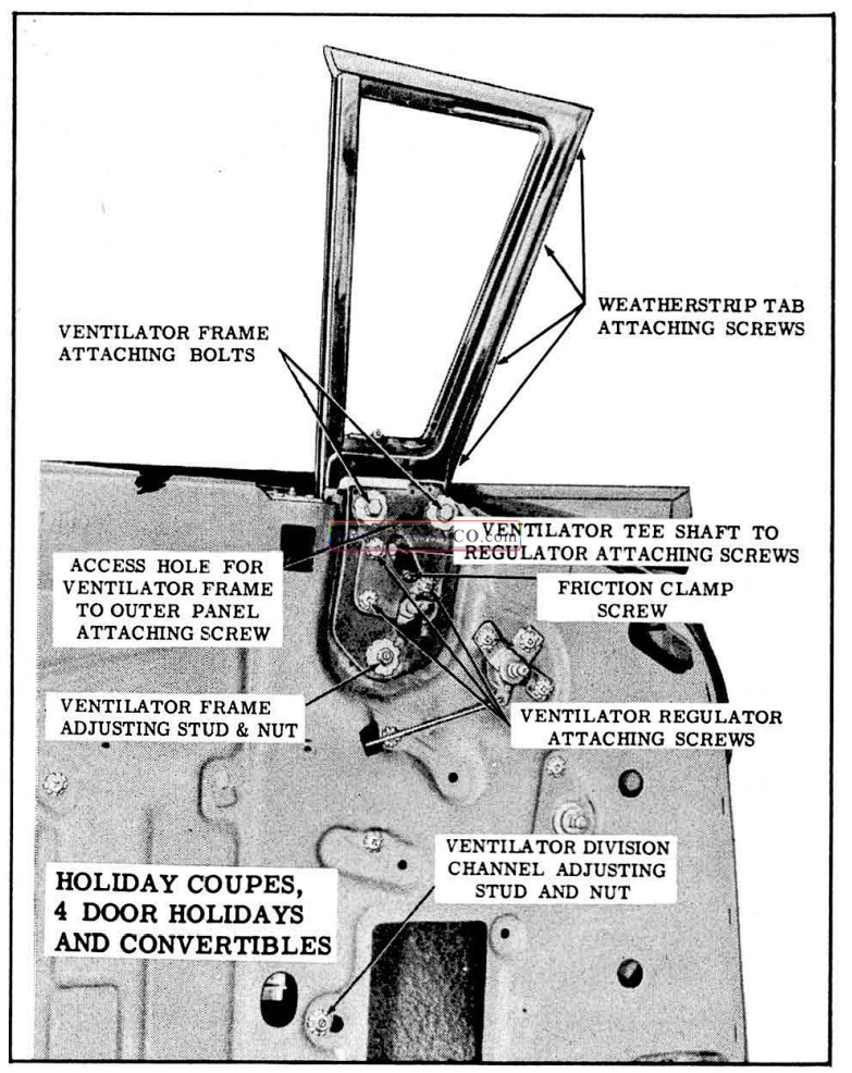
FRONT DOOR VENTILATOR ASSEMBLY (Holiday Coupes, 4 Door· Holidays and Convertibles)
Remove and Install
- Lower door window. Remove door trim assembly and inner panel water deflector.
- Remove weatherstrip tab attaching screws at front of ventilator frame, as indicated in Fig. 17-37.
- Remove ventilator division channel adjusting stud and nut. (See Fig. 17-37)
- Remove ventilator frame to outer panel attaching screw through access hole, shown in Fig. 17 -37. Remove ventilator frame adjusting stud and nut, and attaching bolts. (See Fig. 17-37)
- Carefully work front of ventilator assembly inboard sufficiently to clear door inner panel (at cove area); lift ventilator upward and remove from door.
NOTE: Ventilator regulator may be removed from ventilator as a bench operation by loosening the ventilator tee shaft to regulator shaft attaching screw and removing the regulator attaching screws. (See Fig. 17-37)
- To install front door ventilator assembly, reverse removal procedure. Adjust ventilator assembly as outlined under “FRONT OOOR VENTILATOR ADJUSTMENTS”.
1957 Oldsmobile Front Door Ventilator and Regulator
FRONT DOOR VENTILATOR ADJUSTMENTS
The front door ventilator assembly can be adjusted up or down and in or out at the top for alignment in the door opening and proper weatherstrip contact in the ventilator area. The lower portion of the ventilator division channel can be adjusted in or out and fore or aft for alignment with the door window glass. On the Holiday Coupe, 4 Door Holiday and Convertible styles, the ventilator assembly can be adjusted fore or aft for alignment with the body windshield pillar.
To adjust the ventilator assembly proceed as follows:
- Remove door trim assembly and inner panel water deflector.
- Remove ventilator frame to outer panel attaching screw at location indicated in Fig. 17-37 and 17-36.
- Loosen ventilator division channel adjusting stud nut and ventilator frame adjusting stud nut. (See Figs. 17 -37 and 17-36)
- Loosen ventilator frame attaching bolts. (See Figs. 17-37 and 17 -36)
a. To adjust upper portion of ventilator in or out, turn ventilator frame adjusting stud and ventilator division channel adjusting stud in or out, as required, then tighten stud nuts and all attaching bolts. (See Figs. 17 -37 and 17 -36)
b. To adjust ventilator assembly up or down, and on Holiday Coupes, 4 Door Holidays, and 4 Door Sedans, to adjust ventilator fore or aft, position entire ventilator assembly, as required, then tighten all attaching bolts and stud nuts. (See Figs. 17 -37 and 17 -36) - Install ventilator frame to outer panel attaching screw at location indicated in Figs. 17-37 and 17-36. Seal water deflector to door inner panel and install door trim and inside hardware.
FRONT DOOR VENTILATOR REGULATOR-
Remove and Install
- Raise door window. Remove door trim assembly and inner panel water deflector.
- Loosen ventilator tee shaft to regulator shaft attaching screw. (See Figs. 17 -36 and 17 -37).
- Remove ventilator regulator attaching screws. (See Figs. 17-36 and 17 -37)
- Disengage regulator from ventilator tee shaft and remove from door through forward access hole.
- To install front door ventilator regulator, reverse removal procedure.
VENTILATOR REGULATOR ADJUSTMENTS-
- Excessive “play ” (flutter) of the ventilator at the pivot shaft when the ventilator is in the open position can be corrected by tightening the ventilator tee shaft to regulator shaft screw. (See Figs. 17-36 and 17 -37)
NOTE: Screw should be tightened carefully to avoid stripping threads in regulator spiral gear shaft.
- The operating effort required to open or close the ventilator can be slightly increased or decreased by adjusting the friction clamp screw. (See Fig. 17-36 and 17-37)
FRONT DOOR WINDOW ASSEMBLY (2 Door and 4 Door Sedans)
Remove and Install
- Lower door window. Remove door trim assembly and inner panel water deflector.
- Remove front door ventilator as described under “FRONT OOOR VENTILATOR, REMOVE AND INSTALL”.
- Remove window lower sash channel cam attaching screws indicated in Fig. 17 -38; raise window and remove from between door panels.
CAUTION: On doors with electrically operated window DO NOT OPERATE REGULATOR MOTOR after the window assembly is disengaged from the regulator. Operation of the motor with the load removed may damage the unit.
- To install window assembly, reverse removal procedure.
1957 Oldsmobile Front Door Window and Window Frame Installation
FRONT DOOR WINDOW ADJUSTMENTS (2 Door and 4 Door Sedans)
The door inner panel cam and the lower end of the ventilator division channel may be adjusted to relieve a binding door glass, caused by misalignment of the window with the glass run channels.
- To correct a condition where the glass is “cocked” in the glass run channels, loosen the inner panel cam rear attaching screws. (See Fig. 17 -38); adjust rear of cam up or down as required and tighten screw.
- To adjust the lower portion of the ventilator division channel for alignment with the window, loosen ventilator division channel adjusting stud nut. (See Fig.17 -38).Turn adjusting stud in or out or position lower end of channel fore or aft as required, then retighten adjusting stud nut.
FRONT DOOR WINDOW FRAME (2 Door and 4 Door Sedans)
Remove and Install
- Remove front door ventilator and window assemblies.
- Detach door weatherstrip from window and ventilator area.
- Remove window frame lower attaching bolt at location shown in Fig. 17-38.
NOTE: On 2 Door Sedans remove rubber access hole plug to gain access to attaching bolt.
- At upper front of ventilator, remove 2 screws indicated in Fig. 17-38 securing window frame to ventilator frame.
- Remove window frame attaching screw and bolt at belt line. (See Fig. 17-38)
- Carefully detach window frame from ventilator frame; rotate window frame outward sufficiently to allow attaching tab on frame to clear between door panels; then lift frame upward and remove from door.
- To install front door window frame, reverse removal procedure.
NOTE: If installing new window frame, transfer glass run channel to new frame.
WINDOW FRAME ADJUSTMENT
The lower end of the front door window frame may be adjusted in or out to provide proper weatherstrip contact and/or window frame alignment at top rear of the door. To adjust window frame loosen window frame attaching screw and bolt at belt line. Loosen lower attaching bolt and adjust lower end of window frame as required.
DOOR WINDOW GLASS RUN CHANNELS (2 Door and 4 Door Sedans)
The front door window frame on the 2 Door and 4 Door Sedans is equipped with a vertical glass run channel and an upper glass run channel. The channels are designed to snap into the window frame, and can be removed by squeezing the sides of the channel together and pulling, or carefully prying, the channel from the window frame.
FRONT DOOR WINDOW-(Holiday Coupes, 4 Door Holidays and Convertibles)
Remove and Install
- Lower door window. Remove door trim assembly and inner panel water deflector.
- Remove window cushion adjusting plates. (see Fig. 17 -39)
- Remove window lower sash channel cam attaching screws. (See Fig. 17 – 39) Disengage window assembly from sash channel cam; then lift window assembly upward and re move from door.
CAUTION: On doors with electrically operated windows DO NOT OPERATE REGULATOR MOTOR after the window assembly is disengaged from the regulator. Operation of the motor with the load removed may damage the unit.
- To install window assembly, reverse removal procedure.
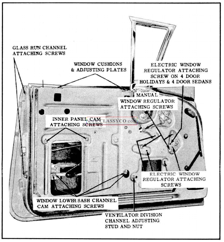
1957 Oldsmobile Front Door Window and Window Regulator
FRONT DOOR WINDOW ADJUSTMENTS (Holiday Coupes, 4 Door Holidays and Convertibles)
To adjust the door window glass for proper contact with the side roof rail weatherstrip, or to relieve a binding door glass caused by misalignment of the glass with the glass run channels, proceed as follows:
- To correct a condition where the glass is “cocked” in the glass run channels, loosen the inner panel cam rear attaching screw (See Fig. 17 -39); adjust rear of cam up or down as required and retighten screw.
- To adjust the upper front position of the window in or out for proper contact with the side roof rail weatherstrip, adjust top of ventilator assembly in or out as described under “FRONT DOOR VENTILATOR ADJUSTMENTS”.
- To adjust the lower portion of the ventilator division channel for alignment with the window, loosen ventilator division channel adjusting stud nut. (See Fig. 17 – 39). Turn adjusting stud in or out to position lower end of channel fore or aft, as required; then retighten adjusting stud nut.
- To adjust rear of window upper frame in or out for proper contact with the side roof rail weatherstrip, or to adjust rear of window in or out at belt line, loosen glass run channel attaching screws (See Fig. 17-39); position channel as required and retighten screws.
- To adjust limit of “up” travel of the window for proper contact with the side roof rail weatherstrip, adjust window cushions. (See Fig. 17 -39)
FRONT DOOR WINDOW GLASS RUN CHANNEL (Holiday Coupes, 4 Door Holidays and Convertibles)
Remove and Install
- Raise door window. Remove door trim assembly and detach rea r portion of inner panel water deflector.
- Remove glass run channel attaching screws. (See Fig. 17 -39)
- Working through rear access hole, lower glass run channel from behind window frame extension and remove from door.
FRONT DOOR WINDOW REGULATOR ASSEMBLY (MANUAL AND ELECTRIC)
Remove and Install
- Lower door window. Remove door trim assembly and inner panel water deflector.
a. Remove window lower sash channel cam attaching screws (See Fig. 17 -39), raise window and prop in “up” position.
CAUTION: On doors with electrically operated windows DO NOT OPERATE REGULATOR after the window assembly is dis engaged from the regulator. Operation of the motor with the load removed may dam age the unit.
- On doors with electrically operated windows, disconnect wiring harness connector from regulator motor through forward access hole.
- Remove ventilator division channel lower adjusting stud and nut. (See Fig. 17-39).
- Remove inner panel cam attaching screws (See Fig. 17 -39); detach cam from regulator arm and remove from door.
- Remove window regulator attaching screws. (See Fig. 17-39) On Holiday Sedans and 4 Door Sedans equipped with electrically operated window regulator, remove regulator attaching screw indicated in Fig. 17-39. Carefully work regulator assembly through rear access hole and remove from door.
NOTE: Instructions for removing the motor from the regulator assembly are out lined under “FRONT DOOR WINDOW REGU LATOR ELECTRIC MOTOR ASSEMBLY”.
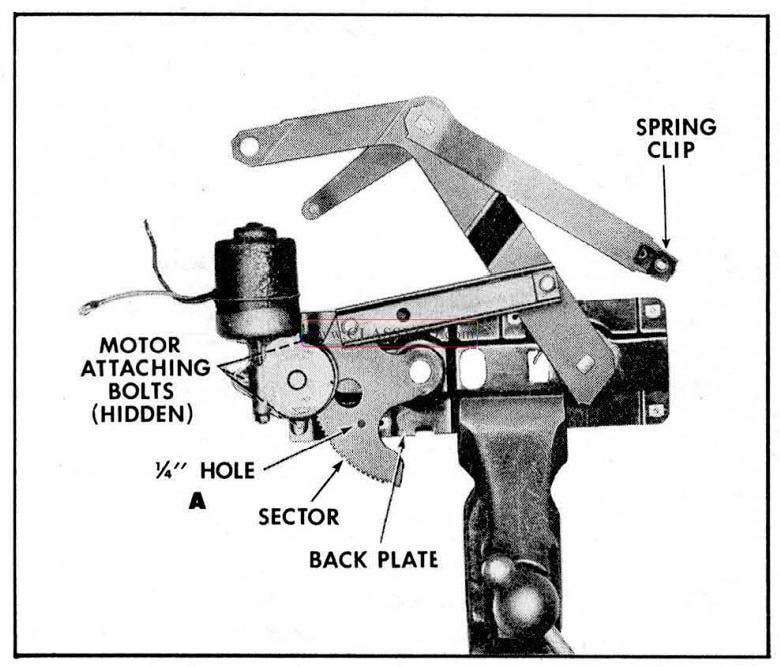
FRONT DOOR WINDOW REGULATOR ELECTRIC MOTOR ASSEMBLY
Remove and Install
- Remove electric window regulator assembly from door as described under “FRONT DOOR WINDOW REGULATOR ASSEMBLY- REMOVE AND INSTALL” and clamp securely in vise. (See Fig. 17-40)
NOTE: The position of the regulator clamped in the vise will vary with the type of regulator and position of the lift arm.
CAUTION: BE SURE TO PERFORM STEPS 2 AND 3 BEFORE ATTEMPTING TO REMOVE THE MOTOR FROM THE REGULA TOR. The regulator lift arm, which is under tension from the counter-balance spring can cause serious injury if the motor assembly is re moved without locking the sector in position.
- Drill 1/4″ hole through backplate and sector at location indicated by “A”, in Fig. 17-40.
NOTE: Location of hole in backplate will vary, depending on position of sector. Do not locate hole less than 1/2″ away from edge of backplate or sector.
- Insert 3/16″ bolt through holes in backplate and sector and install nut to bolt. (Do not tighten nut.)
- Remove the 3 attaching bolts and remove motor assembly from regulator. (See Fig. 17-40)
NOTE: Clean off steel chips from the regulator sector and motor pinion gear after drilling operation.
- To install, reverse removal procedure. The regulator lift arms may be moved up or down manually so that motor pinion gear will mesh with· teeth on regulator sector.
NOTE: Be sure to remove temporary nut and bolt from regulator after motor is in stalled.
1957 Oldsmobile Front Door Regulator and Electric Motor Assembly
FRONT DOOR LOCKING MECHANISMS
All door locks are the rotary bolt-type lock with the inter lock feature. With the inter lock feature it is very important that the lock extension engage properly in the striker notch and that, where necessary, striker emergency spacers of the proper thickness are used to obtain proper engagement. On the 98 Holiday Coupe and Convertible and all 4 Door Holidays, an adjusting nut is provided at the lower end of the door outside handle connecting rod, which can be adjusted to provide proper action of the outside handle push burton. An adjusting screw on the end of the outside handle push button shaft on the 4 Door Sedans is provided for the same purpose. The front door locks are covered by a plastic bag.
DOOR LOCK SPRING CLIP
A redesigned spring clip is used on the door lock levers to secure the connecting rods to the lock levers. A slot in the spring clip provides easier disengagement of the clip, thereby facilitating easier detachment of the lock connecting rods from the lock.
To disengage spring clips, use a screw driver or other suitable tool to slide clip out of engagement. Fig. 17-41 shows a door lock spring clip engaged and disengaged.
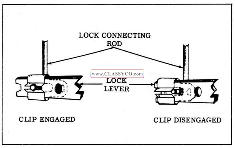
1957 Oldsmobile Door Lock Spring Clip
DOOR LOCK-(2 Door Sedans)
Remove and Install
- Raise window. Remove door trim assembly and inner panel water deflector.
- Remove window frame bolt access hole plug from lock pillar. (See Fig. 17 -42) Through access hole, remove window frame lower attaching bolt.
- Remove door arm rest anchor plate attaching screw, (See Fig. 17 -42) and re move anchor plate.
- Remove door lock remote control attaching screw, (See Fig. 17 -42) and remove remote control.
- Detach remote control connecting rod from clip, (See Fig. 17 -42) then detach rod from door lock and remove rod from door.
- Remove door lock attaching screws. (See Fig. 17-42)
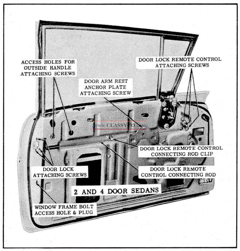
1957 Oldsmobile Door Lock Removal
- Pull lower end of window frame forward sufficiently to bring lock bolt housing through hole in door lock pillar; then lower lock until it can be rotated around window frame and remove from door.
- To install door lock, reverse removal procedure. Prior to installation of lock, apply a ribbon of medium bodied sealer (approximately 1/4″ in diameter) across face of lock frame, as indicated in Fig. 17 -43.
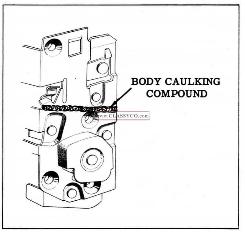
1957 Oldsmobile Front Door Lock Sealing
NOTE: Sealer is applied to outer surface of lock bag.
FRONT DOOR LOCK-(4 Door Sedans)
Remove and Install
- Raise door window. Remove door trim assembly and inner panel water deflector.
- Through large access hole disengage spring clips and detach the remote control connecting rod, the inside locking connector-to-lock rod, and lock cylinder connecting rod from lock.
- Remove door lock attaching screws and remove door lock from door through large access hole.
- To install front door lock, reverse removal procedure.
NOTE: Prior to installation of front door lock apply a ribbon of medium-bodied sealer (approximately 1/4 ” in diameter) across face of lock frame, as indicated in Fig. 17-43. Sealer is applied to outer surface of lock bag.
- Adjust nut on end of outside handle push button shaft to provide between 1/32 ” and 1/8″ free travel of the push button; then tighten jamb nut.
FRONT DOOR INSIDE LOCKING ROD TO LOCK CONNECTOR ASSEMBLY-(4 Door Sedans)
Remove and Install
- Raise door window. Remove door trim assembly and inner panel water deflector.
- Through large access hole, carefully snap inside locking rod and inside locking connector to lock rod from connector assembly.
- Remove 3 screws securing connector assembly to door lock pillar and remove connector assembly from door.
- To install connector assembly, reverse removal procedure.
FRONT DOOR LOCK-(Holiday Coupes, 4 Door Holidays and Convertibles)
Remove and Install
- Raise door windows, remove door trim assembly and inner panel water deflector.
- On Holiday Coupes and Convertibles remove door window assembly.
- Remove glass run channel attaching screws on face of lock pillar, (See Fig. 17-44) and remove channel from door. On 4 Door Holidays lower glass run channel from behind window frame extension to remove from door.
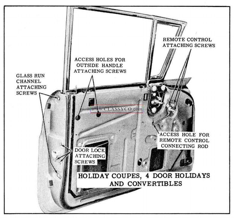
1957 Oldsmobile Front Door Lock Removal
- On Holiday Coupes and Convertibles proceed as follows:
a. Remove door arm rest anchor plate attaching screws, (See Fig. 17 -42) and remove anchor plates where present.
b. Remove door lock remote control attaching screws. (See Fig. 17 -42) and remove remote control.
c. Detach remote control connecting rod from clip, (See Fig. 17 -42) then detach rod from door lock and remove from door. - a. On all styles, disengage spring clip and detack lock cylinder connecting rod from lock. (See Fig. 17-45)
b. On 98 Holiday Coupes, 98 Convertibles and all 4 Door Holidays, disengage spring clip and detach outside handle push button connecting rod adjusting nut from lock. (See Fig. 17 -45)
c. On 4 Door Holidays disengage spring clips and detach remote control connecting rod and inside locking rod from lock. (See Fig. 17-45).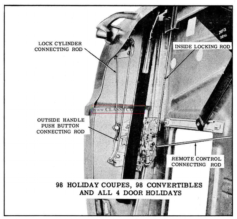
1957 Oldsmobile Front Door Lock Removal (2)
- Remove door lock attaching screws, (See Figs. 17-42 and 17 – 44) and remove door lock from door through large access hole.
- To install front door lock, reverse removal procedure.
NOTE: Prior to installation of front door lock on all styles except 4 Door Holidays, apply a ribbon of medium bodied sealer (approximately 1/4″ in diameter) across f ace of lock frame, as indicated in Fig. 17-43. Sealer is applied to outer surface of lock bag.
- On 98 Holiday Coupes, 98 Convertibles and all 4 Door Holidays adjust nut ·on end of outside handle push button connecting rod to pro vide between 1/32″ and 1/8″ free travel of the push button.
FRONT DOOR LOCK REMOTE CONTROL AND CONNECTING ROD-
Remove and Install
- Raise door window. Remove door trim assembly and inner panel water deflector.
- On 4 Door Holidays, disengage spring clip and detach remote control connecting rod from lock. (See Fig. 17-45)
- Remove remote control attaching screws, (See Figs. 17 -42 and 17 -44) and remove remote control.
- On all styles except 4 Door Holidays and 4Door Sedans, detach remote control connecting rod from clip on inner panel, disengage rod from door lock, and remove from door.
- On 4 Door Holidays and 4 Door Sedans remove remote control connecting rod from door through access hole, shown in Fig. 17-44.
- To install door lock remote control, reverse removal procedure.
NOTE: Check operation of door lock before installing inner panel water deflector.
REMOTE CONTROL ADJUSTMENTS
- Remove door trim assembly. Detach upper front of door inner panel water deflector sufficiently to gain access to remote control attaching screws.
- Loosen remote control attaching screws. (See Fig. 17-42) Adjust remote control in a rear ward direction to just take out linkage clearances. Tighten screws.
- Check operation of door lock before resealing water deflector.
FRONT DOOR OUTSIDE HANDLE ASSEMBLY
Remove and Install
- Raise door window. Remove door trim assembly and inner panel water deflector.
- Through large access hole disengage spring clip and detach lock cylinder connecting rod from door lock.
- On 98 Holiday Coupes, 98 Convertibles and all Holiday Sedans, disengage spring clip and detach outside handle push button connecting rod adjusting nut from lock.
- Through access holes for outside handle attaching screws, (See Fig. 17-42 and 17-44) remove handle attaching screws. Remove outside handle with attached connecting rod or rods from door. Remove connecting rods or rods with anti-rattle clips from handle assembly.
- To install door outside handle assembly, re verse removal procedure, making sure gaskets are installed between the handle and door outer panel at front and rear attaching points.
NOTE: On 98 Holiday Coupes, 98 Convertibles, and all 4 Door Holidays adjust nut on end of outside handle push button connecting rod to provide between 1/ 32″ and 1/8″ free travel of the push button.
On 4 Door Sedans adjust nut on end of outside hand le push button shaft to provide between 1/32″ and 1/8″ free travel of the push button; then tighten jamb nut.
FRONT DOOR OUTSIDE HANDLE ASSEMBLY
The front door outside handle assembly includes the lock cylinder assembly. This necessitates the removal and disassembly of the outside handle assembly to remove the lock cylinder assembly.
Disassembly
- Remove door outside handle assembly as previously described.
- While maintaining pressure to hold component parts within handle, use a suitable tool and remove spring retainer; then remove parts as shown in appropriate figure:
a. Fig. 17-46 for 98 Holiday Coupes, 98 Convertibles and all 4 Door Holidays.
1957 Oldsmobile Disassembly of Front Door Outside Handle Assembly
b. Fig. 17-47 for two-door styles except 98 Holiday Coupe and 98 Convertible.
1957 Oldsmobile Disassembly of Front Door Outside Handle Assembly
c. Fig. 17-48 for 4 Door Sedans.
1957 Oldsmobile Disassembly of Front Door Outside Handle
NOTE: To disengage pawl from stop washer retainer or bell crank lever, rotate pawl to cut-outs and remove.
- To assemble door outside handle, first engage pawl to bell crank lever or stop washer retainer; then reverse removal procedure, making certain open end of spring retainer is located at nipple on ad jacent parts. See appropriate figure.
a. Fig. 17-49 for 98 Holiday Coupe, 98 Convertible and all 4 Door Holidays.
1957 Oldsmobile Front Door Outside Handle Assembly
b. Fig. 17-50 for 2 door styles except 98 Holiday Coupe and 98 Convertibles.
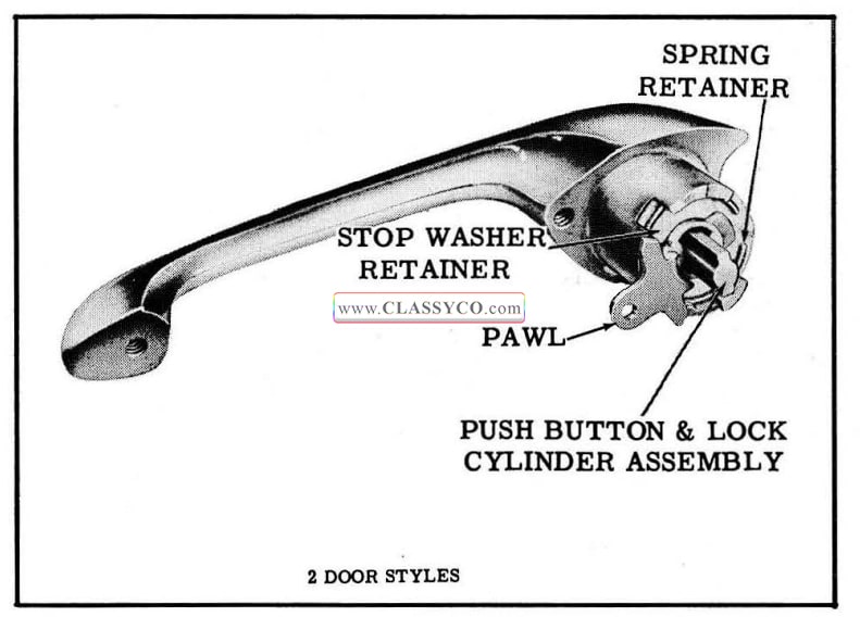
1957 Oldsmobile Front Door Outside Handle Assembly (2)
FRONT DOOR LOCK CYLINDER
The front door lock cylinder is located in the door lock outside handle push button assembly. To remove the lock cylinder, it is necessary to re move the push button assembly from the handle.
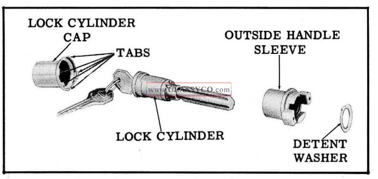
1957 Oldsmobile Disassembly Front Door Outside Handle Lock Cylinder Assembly
Disassembly and Assembly
- Remove and disassemble door outside handle as previously described.
- With a suitable tool remove detent spring from lock cylinder.
- Carefully bend out tabs securing lock cylinder cap and remove Jock cylinder sleeve and lock cylinder.
- To assemble, reverse removal procedure.
NOTE: When installing detent spring make certain raised portions of spring rest in depressions in sleeve.
REAR DOOR ASSEMBLY
The rear doors are attached to the center pillar by 2 butt-type hinges. The lower hinge, which is new in design, has an integral door check and hold-open and is secured to an anchor plate on the door and center pillar by 3 screws at each location. The upper hinge is secured to an anchor plate on the door hinge pillar by 3 screws and to an upper hinge support on the center pillar by 3 bolts.
Remove
Either of the following 2 methods can be used to remove the door from the body.
- The door can be removed from the hinge straps.
- The door and hinge straps can be removed from the center pillar.
a. Operate window to down position.
b. Clean off excess sealer around each hinge strap and scribe location of hinge straps on door hinge pillar or center pillar depending on method of removal being used.
c. On doors with electrically-operated windows proceed as follows:
(1) Remove 2 screws securing electrical conduit to door hinge pillar, bend down tabs securing harness to conduit, and remove conduit.
(2) Remove necessary hardware and remove door trim assembly.
(3) Detach water deflector sufficiently to gain entrance to large access hole.
(4) Through access hole, detach wire har ness from clips and disconnect harness wires from window regulator motor leads. Then remove wire harness from door.
d. Depending on method of removal, properly support door and remove 3 upper and lower hinge to door pillar attaching screws at door hinge pillar or 3 upper and lower hinge to center pillar attaching screws. (See Fig. 17-52)
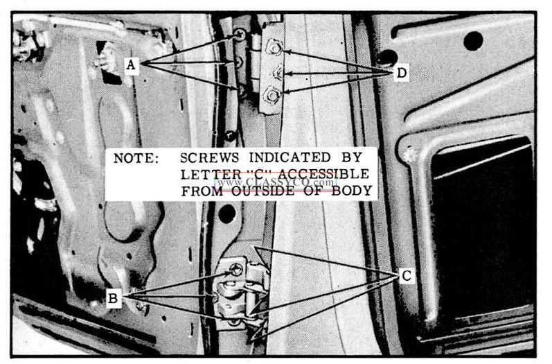
1957 Oldsmobile Rear Door Hinges
NOTE: Screws securing lower hinge strap to center pillar are accessible from outside of body when door is in full “open” posit ion.
e. Remove door from body opening.
Install
- With scraper and mineral sp1nts, clean off old sealing compound at hinge areas.
NOTE: This operation should be performed carefully to avoid possibility of soiling adjacent trim material.
- Apply a coat of heavy-bodied sealer to attaching surfaces of hinge straps or to corresponding surfaces of door or body, as indicated in Fig. 17-53. It is important to obtain complete coverage with sealer to obtain proper sealing and anti-squeak effects. In addition, lubricate frictional surface of door hold-open assist assembly as outlined in Lubrication Section.
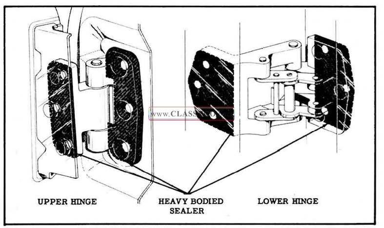
1957 Oldsmobile Sealing Rear Door Hinges
- Lift door into position. Install screws and/or bolts loosely, then align straps within scribe mark on pillar and tighten screws and/or bolts. Check door for alignment.
- On doors with electrically-operated windows proceed as follows:
a. Install wire harness to attaching clips in side of door and connect ends to motor leads. Check operation of window.
b. Install conduit to hinge pillar and secure wire harness in conduit with retaining tabs.
c. Reseal water deflector to inner panel as specified under “DOOR INNER PANEL WATER DEFLECTOR”.
d. Install door trim assembly and previously removed door hardware.
REAR DOOR ADJUSTMENTS
The rear door hinge adjustments differ from those performed on previous models. “In and out ” and “up and down ” adjustments are provided at the door hinge pillar. “Fore and aft” adjustments are provided at the center pillar.
When checking the door for alignment, remove the door lock striker from the body pillar to allow the door to hang free on its hinges.
NOTE: After performing any adjustments the rear door window should be checked for proper alignment with the side roof rail weatherstrip and adjusted where required. In addition, the door lock extension-to-striker engagement should be checked and adjusted if necessary.
- For “in and out ” or “up and down” adjustments loosen hinge to door pillar attaching screws, (See Fig. 17 -52), adjust door as required, and tighten screws.
NOTE: When performing “in and out” adjustments adjust one hinge at a time so that the “up and down” adjustment is maintained.
- To adjust the door “fore and aft”, loosen hinge to center pillar attaching screws, (See Fig. 17 -52), adjust door as required, and tighten screws and bolts.
REAR DOOR WINDOW ASSEMBLY (4 Door Sedans)
Remove and Install
- Lower rear door window assembly. Remove door trim assembly and inner panel water deflector.
- Remove window rear guide upper and lower attaching studs and nuts, (Fig. 17 -54), then disengage guide from shoes on window lower sash channel and remove from door by pulling guide upward through cutout in top of door inner panel.
- Remove window lower sash channel cam attaching screws. (See Fig. 17-54)
CAUTION: On doors with electrically op era ted window regulators 00 NOT OPERATE REGULATOR MOTOR after the window assembly is disengaged from the regulator. Operation of the motor with the load removed may damage the unit.
- Carefully lift window upward and inboard to clear window frame as indicated in Fig. 17-55, and remove window assembly from door.
- To install window assembly, reverse removal procedure. Prior to installation of the window rear guide, lubricate channel portion of guide with 630 AA W Lubriplate along entire length of channel. Check operation of window assembly and, where required, adjust window as described under “REAR DOOR WINDOW AD JUSTMENTS”.
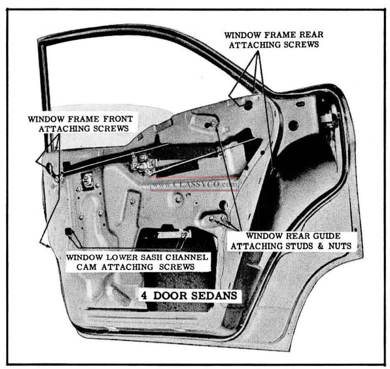
1957 Oldsmobile Rear Door Window and Window Frame Removal
REAR DOOR WINDOW ADJUSTMENTS (4 Door Sedans)
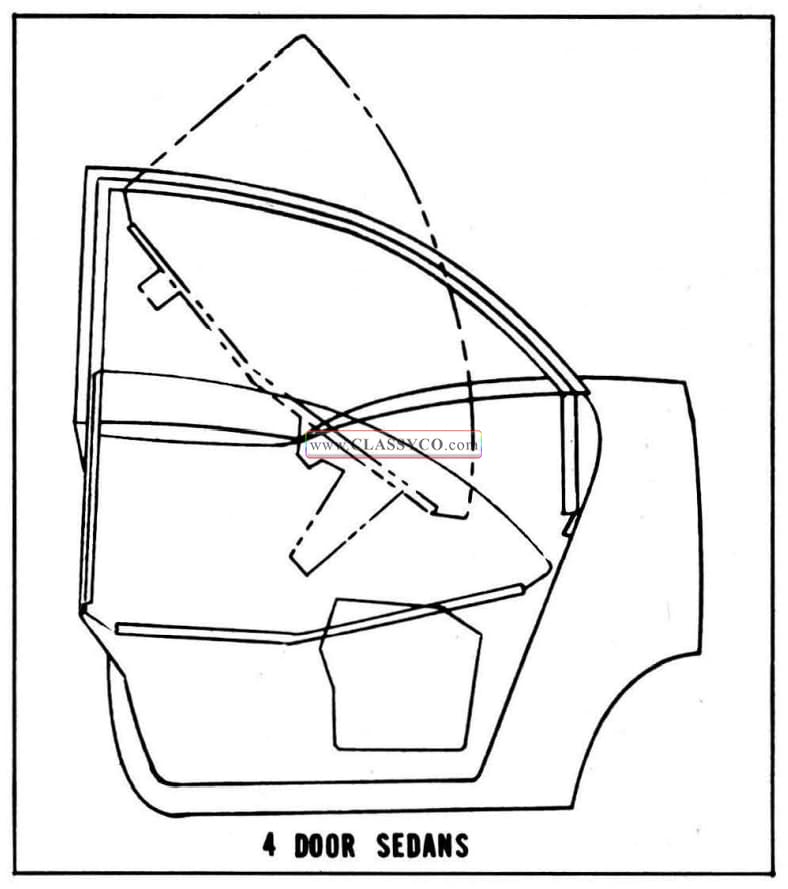
1957 Oldsmobile Rear Door Window Installation
To adjust the window fore or aft or to relieve a binding condition caused by window being misaligned with the glass run channels, proceed as follows:
- Remove rear door trim assembly and inner panel water deflector.
- To adjust window assembly in or out for alignment with the glass run channels, loosen rear guide stud nuts and turn adjusting studs (See Fig. 17 -56), in or out as required. Tighten adjusting stud nuts.
- To adjust front of window up or down for align men with glass run channels, loosen inner panel cam rear attaching screw. (See Fig. 17 -56) Move rear of cam and front of window up or down, as required; then tighten cam attaching screws.
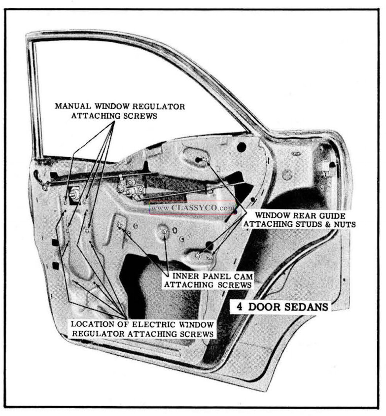
1957 Oldsmobile Rear Door Window Adjustments and Window Regulator Removal
REAR DOOR WINDOW REAR GUIDE (4 Door Sedans)
Remove and Install
- Lower rear door window assembly. Remove door trim assembly and inner panel water deflector.
- Remove window rear guide upper and lower attaching studs and nuts (See Fig. 17 -56); then disengage guide from shoes on window lower sash channel and remove from door by pulling guide upward through cut-out in top of door inner panel.
- To install window rear guide, reverse removal procedure.
NOTE: Prior to installation of the guide, lubricate channel portion of guide with 630 AA W Lubriplate along entire length of channel. Check operation of window assembly and, where required, adjust window as described under “REAR DOOR WINDOW ADJUSTMENTS”.
REAR DOOR WINDOW REGULATOR (4 Door Sedans)
Remove and Install
- Lower rear door window assembly. Remove door trim assembly and inner panel water deflector.
- On doors with electrically operated window regulators, disconnect wire harness connector from regulator motor.
CAUTION: DO NOT OPERATE REGULA TOR MOTOR after the window assembly is disengaged from the regulator or after the regulator is removed from the door. Operation of the motor with the load removed may damage the unit.
- Remove window lower sash channel cam attaching screws (See Fig. 17 -54), then lift window assembly and prop in up position.
- Remove inner panel cam attaching screws (See Fig. 17 -56), and remove regulator assembly from door through large access hole.
- Remove window regulator attaching screws, (See Fig. 17-56), then detach cam from regulator arms and remove from door.
To remove electric motor from regulator assembly see “REAR OOOR WINDOW REGULATOR ELECTRIC MOTOR ASSEMBLY – REMOVE AND INSTALL”.
- To install window regulator assembly, reverse removal procedure.
REAR DOOR WINDOW FRAME ASSEMBLY(4 Door Sedans)
Remove and Install
- Remove rear door window.
- Detach door weatherstrip from window frame. Remove door window frame front and rear attaching screws. (See Fig. 17-54)
- Carefully lift window frame upward, rotate rear of frame outward, and remove from door.
- To install door window frame assembly, reverse removal procedure.
NOTE: If installing new window frame transfer glass run channels to new frame.
REAR DOOR WINDOW FRAME ADJUSTMENTS
The upper portion of the rear door window frame can be adjusted in or out to provide proper weatherstrip contact along the upper portion of the door opening. To adjust the window frame proceed as follows:
- Remove door belt finishing molding. Loosen window frame front and rear attaching screws. (See Fig. 17 -54)
- Position lower ends of window frame in or out to provide proper weatherstrip contact along the upper portion of the door opening.
- Tighten all window frame attaching screws.
REAR DOOR WINDOW GLASS RUN CHANNELS-(4 Door Sedans)
The rear door window frame on the 4 Door Sedans is equipped with a vertical glass run channel and an upper glass run channel. The channels are designed to snap in the window frame and can be removed by squeezing the sides of the channel together and pulling or carefully prying the channel from the window frame.
REAR DOOR WINDOW ASSEMBLY (4 Door Holidays)
Remove and Install
- Raise door window assembly. Remove door trim assembly and inner panel water deflector.
- Through access hole, shown in Fig. 17-57, loosen female wedge plate attaching screw. Lower window; then through large access hole remove wedge plate from front of window lower sash channel.
- Remove door glass run channel inner front strip attaching screw (See Fig. 17-57), and remove strip.
- Remove window cushion adjusting plate screws (See Fig. 17-57), and remove cushion and adjusting plate.
- Through access holes remove window lower sash channel cam attaching screws (See Fig. 17 -57), and detach cam from window sash channel.
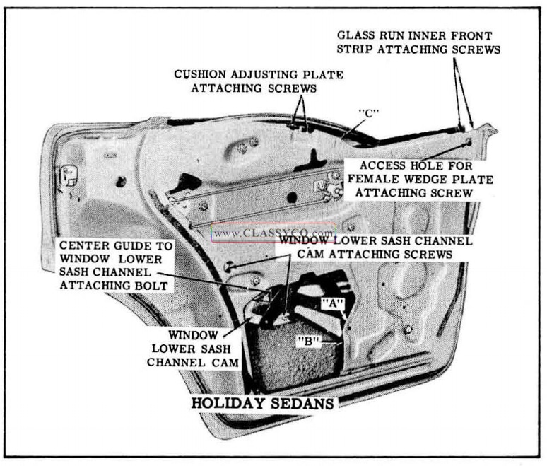
1957 Oldsmobile Rear Door Window Removal
CAUTION: On doors with electrically operated window regulators DO NOT OPERATE REGULATOR MOTOR after the window assembly is disengaged from the regulator. Operation of the motor with the load removed may damage the unit.
- Using a screw driver at location “A” (See Fig. 17-57), disengage spring clip on end of regulator balance arm. At the same time insert another screw driver, at location “8”, and disengage regulator balance arm from pin on window lower sash channel.
- Lift window assembly with attached center guide straight up between door panels so that the center guide comes out through depression in inner panel, at location “C” (See Fig.17-57)
- To install rear door window assembly, reverse removal procedure.
NOTE: Prior to installing the window assembly, apply 630 AA W Lubriplate or its equivalent to the frictional surfaces of the front, center, and rear guides.
When engaging center guide over center guide shoe make sure anti-rattle clip is also engaged in channel of guide. After installation of window assembly and before installing inner panel water deflector, check operation of window. Check for proper window frame contact with the side roof rail weatherstrip and window front frame weather strip contact with the front door window. Where necessary, adjust window as described under “REAR DOOR WINDOW ADJUSTMENTS – 4 Door Holidays.
REAR DOOR WINDOW ADJUSTMENTS (4 Door Holidays)
IMPORTANT: The rear door assembly should be properly aligned in the body opening before adjusting the rear door window.
Adjustments have been provided to insure a proper weatherseal between window frames and weatherstrips, as indicated in Fig. 17-58, and also to provide proper operation of the window. The following window adjustments are for both manually and electrically-operated windows.
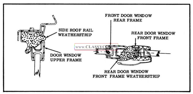
1957 Oldsmobile Door Window Frame Weatherstrip Contact
To perform rear door window adjustments, raise rear door window and remove door trim assembly and inner panel water deflector.
- “In and out” adjustments of the lower front portion of the window:
a. First loosen male wedge plate attaching screws at door hinge pillar.
b. Loosen front guide upper attaching screws at door hinge pillar and lower attaching stud and nut.
c. Adjust both upper and lower ends of the guide the same amount in or out as required.
d. Tighten front guide attaching screws and stud nut.
e. With window in FULL UP position, tighten male wedge plate screws. (See Fig.17-59) - “In and out” adjustment of the rear portion of the window:
a. Loosen rear guide upper and lower attaching stud nuts.
b. Adjust both upper and lower studs the same amount “in or out”, as required, then tighten stud nuts. (See Fig. 17 -59) - “In and out” adjustment of top of window frame:
a. First loosen male wedge plate screw located on door hinge pillar.
b. Loosen center guide shoe jam nut.
c. Turn center guide shoe “in or out”, as required, and retighten jam nut.
d. With window in FULL UP position tighten male wedge plate screws. (See Fig. 17-59) - “Up and down” adjustment of front of window:
a. First loosen male wedge plate attaching screws, located on door hinge pillar.
b. Loosen inner panel cam attaching screws, position front of cam and window “up” or “down”, as required, and retighten cam screws.
c. With window in FULL UP position tighten male wedge plate screws. (See Fig. 17-59) - “Up and down” adjustment of rear of window:
a. Through access hole loosen window lower sash channel cam rear attaching screw.
b. Position rear of window and cam “up or down•·, as required, and retighten cam screw. (See Fig. 17-59) - “Fore and aft” adjustment of window:
a. First loosen female wedge plate screw through access hole.
b. Operate window to desired position, then back window off slightly (approximately 1/16″).
c. Position female wedge plate tight against male wedge plate and tighten wedge plate screw through access hole. (See Fig. 17 -59) - To limit the “up” travel of the rear of the window adjust window cushion and adjusting plate. (See Fig. 17 -59)
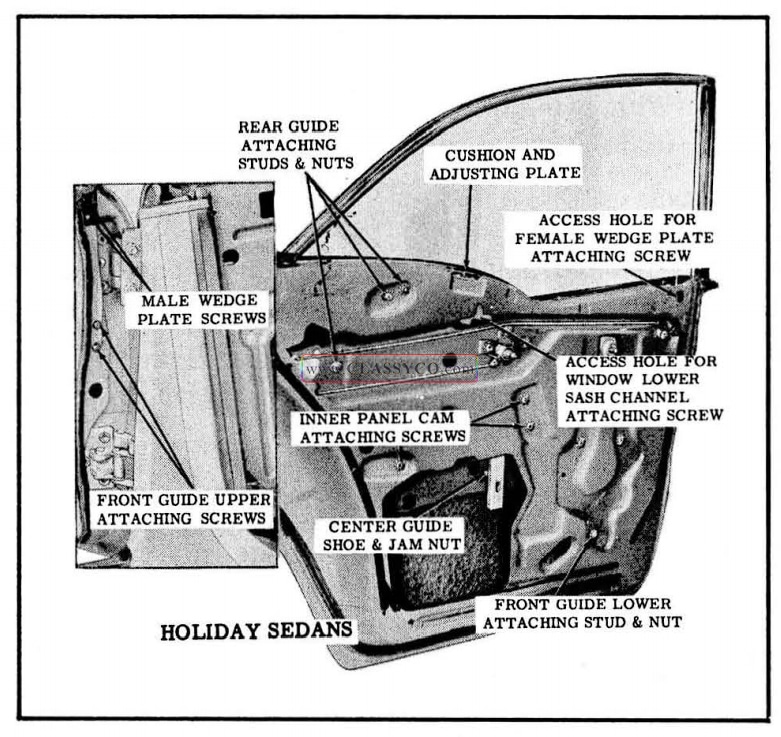
1957 Oldsmobile Rear Door Window Adjustments
REAR DOOR WINDOW FRONT GUIDE (4 Door Holidays)
Remove and Install
- Raise rear door window. Remove door trim assembly and inner panel water deflector.
- On doors with electrically operated window regulators remove center guide as described under “REAR OOOR WINOOW CENTER GUIDE-REMOVE AND INSTALL”.
- Remove front guide upper attaching screws located on door hinge pillar, and lower attaching nut and stud. (See Fig. 17-59)
- Remove guide with attached anti-rattle support and lower bumper through large access hole.
- To install rear door window front guide, reverse removal procedure.
NOTE: Before installing guide, lubricate the inboard and outboard frictional surface with 630 AA W Lubriplate or its equivalent.
After installation of guide, adjust guide in or out for proper contact of the rear door window frame weatherstrip with the front door window frame, as indicated in Fig. 17-58.
REAR DOOR WINDOW CENTER GUIDE (4 Door Holidays)
Remove and Install
- Lower rear door window. Remove door trim assembly and inner panel water deflector.
- Remove center guide-to-window lower sash channel attaching bolt. (See Fig. 17 -57)
- Carefully remove guide from window lower sash channel, then slide guide off center guide shoe and remove from door.
NOTE: If desired, center guide shoe may be removed by loosening jam nut, shown in Fig. 17-60, and unscrewing shoe from weld nut on support.
- To install center guide, reverse removal procedure.
NOTE: Before installing guide, lubricate channel of guide with 630 AA W Lubriplate or its equivalent.
When engaging center guide over center guide shoe, make sure anti-rattle clip is also engaged in channel of guide.
After installation of center guide and before installing inner panel water deflector, adjust center guide shoe to provide proper window frame contact with the side roof rail weatherstrip, as indicated in Fig. 17-58.
REAR DOOR WINDOW REAR GUIDE (4 Door Holidays)
Remove and Install
- Raise door window. Remove door trim assembly and inner panel water deflector.
- Loosen rear guide upper and lower attaching stud nuts and remove studs. (See Fig. 17 -60)
- Disengage guide from shoes on window frame, then lower guide between door panel and re move from door through access hole.
- To install rear guide, reverse removal procedure.
NOTE: Before installing rear guide, lubricate the inboard and outboard frictional sur faces with 630 AAW Lubriplate or its equivalent.
When installing rear guide, make sure upper end of guide is between nylon shoes on window frame before securing guide to door inner panel. After installation of rear guide and before installing inner panel water deflector adjust guide studs “in” or “out” for proper contact of the rear of the window frame with the side roof rail weatherstrip and with the door glass run channel outer sealing strip.
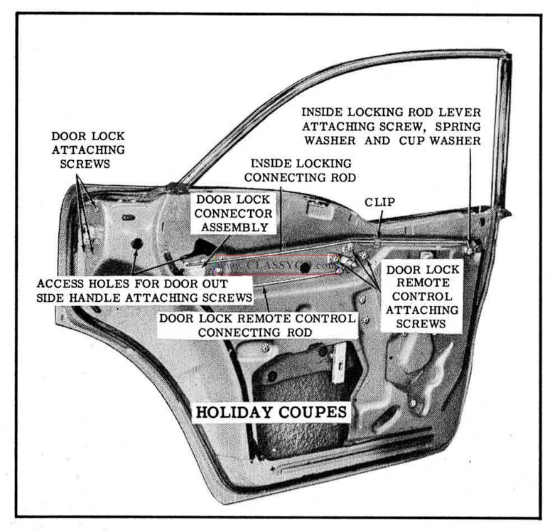
1957 Oldsmobile Rear Door Locking Mechanisms
REAR DOOR WINDOW REGULATOR (4 Door Holidays)
Remove and Install
- Lower rear door window. Remove door trim assembly and inner panel water deflector.
- On doors with electrically-operated window regulators disconnect wire harness connector from regulator motor.
CAUTION: DO NOT OPERATE REGULATOR MOTOR after the window assembly is disengaged from the regulator or after the regulator is removed from the door. Operation of the motor with the load removed may damage the unit.
- Using a screw driver, at location “A” (See Fig. 17 -61), disengage spring clip on end of regulator balance arm. At the same time insert another screw driver, at location “B”, and pry regulator balance arm from pin on window lower sash channel.
- Remove window lower sash channel cam attaching screws. Detach cam from window and from regulator lift arm and remove cam from door.
- Lift window to “up” position; engage female wedge plate with male wedge plate on door hinge pillar, then prop rear of window in “up” position.
- Remove inner panel cam attaching screw (See Fig. 17-61); detach cam from regulator balance arm and remove front door.
- Loosen center guide shoe jam nut (See Fig. 17-60); unscrew guide shoe from support and remove shoe from guide. Swing center guide upward to provide clearance for removing regulator.
- Remove regulator attaching screws. (See Fig. 17 -61) Position regulator balance arms in line with lift arm to facilitate removal of regulator assembly through access hole.
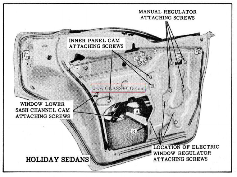
1957 Oldsmobile Rear Door Window Regulator Removal
To remove electric motor from regulator assembly see “REAR DOOR WINDOW REGULATOR ELECTRIC MOTOR ASSEMBLY – REMOVE AND INSTALL”.
- To install window regulator assembly, reverse removal procedure.
NOTE: Before installing window regulator make sure spring clip on regulator balance arm is properly installed. If clip is damaged, replace with new clip.
When installing center guide shoe into channel of center guide, make sure anti-rattle clip is also engaged in channel of guide.
REAR DOOR WINDOW REGULATOR ELECTRIC MOTOR ASSEMBLY (Holiday Sedans and 4 Door Sedans)
Remove and Install
- Remove electric window regulator assembly from door and clamp securely in a vise, as shown in illustration. (See Fig. 17-40)
NOTE: The position of the regulator clamped in the vise will vary with the type of regulator and position of the lift arm.
CAUTION: BE SURE TO PERFORM STEPS 2 AND 3 BEFORE ATTEMPTING TO REMOVE THE MOTOR FROM THE REGULATOR. The regulator lift arm, which is under tension from the counter-balance spring, can cause serious injury if the motor is removed with out locking the sector in position.
- Drill a 1/4 ” hole through sector and backplate at location “A ” indicated in Fig. 17-40.
NOTE: Location of hole in backplate will vary depending on position of sector. Do not locate hole less than 1/2″ away from edge of backplate or sector.
- Insert a 3/16 ” bolt through hole in backplate and sector and install nut to bolt. (Do not tighten nut.)
- Remove the 3 motor attaching bolts and remove motor assembly from regulator.
NOTE: Clean off steel chips from the regulator sector and motor pinion gear after drilling operation.
- To install, reverse removal procedure. Regulator motor rubber pad should be cemented to inner panel side of motor.
NOTE: Be sure to remove temporary nut and bolt from regulator after motor is installed.
REAR DOOR LOCKING MECHANISMS
All door locks are the rotary bolt type lock with the inter-lock feature. With the inter-lock feature it is very important that the lock extension engages properly in the striker notch and that, where necessary, striker emergency spacers of the proper thickness are used to obtain proper engagement as described under “DOOR LOCK STRIKER ADJUSTMENTS”.
DOOR LOCK SPRING CLIPS
A redesigned spring clip is used on door lock levers to secure the connecting rods to the lock levers. A slot in the spring clip provides easier disengagement of the clip, thereby facilitating easier detachment of the lock connecting rods from the lock.
To disengage spring clips, use a screw driver or other suitable tool to slide clip out of engagement. Fig. 17-41 shows a door lock spring clip engaged and disengaged.
REAR DOOR LOCK ASSEMBLY
Remove and Install
- Raise door window. Remove door trim assembly and inner panel water deflector.
- a. On 4 Door Sedans, through large access hole, disengage spring clips securing remote control and inside locking connecting rods to lock and detach connecting rods from lock. (See Fig. 17 -62)
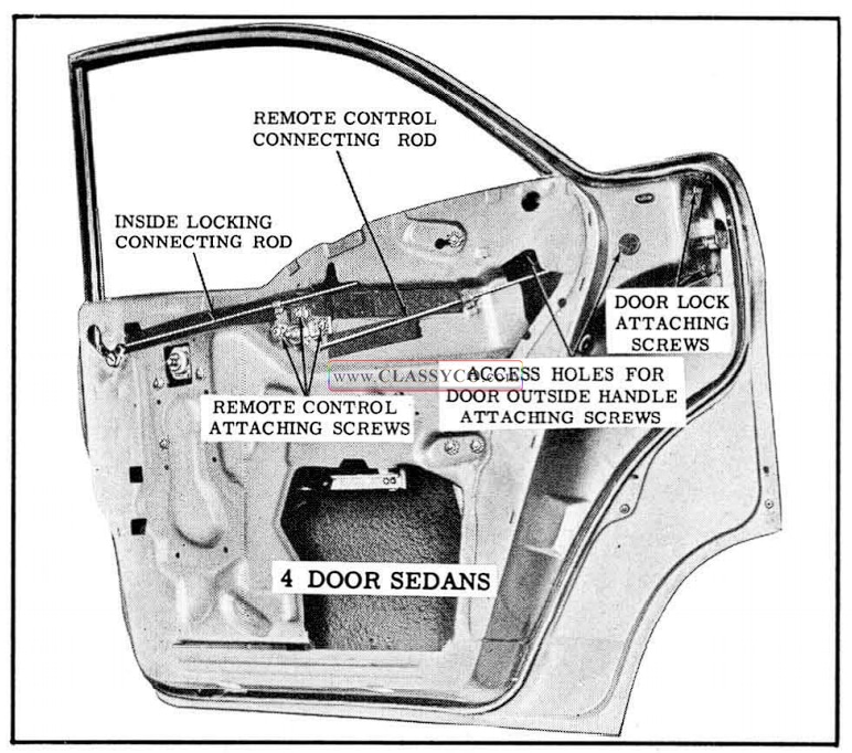
1957 Oldsmobile Rear Door Locking Mechanisms (2)
b. On 4 Door Holidays, through large access hole, disengage spring clips and detach lock connector-to-lock connecting rods from lock. (See Fig. 17-63)
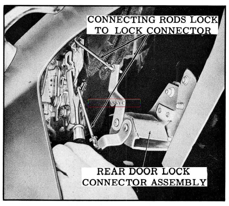
1957 Oldsmobile Rear Door Lock Removal
- Remove door lock attaching screws at door lock pillar. (See Fig.17-60 and 17 -62) Lower lock between door panels and remove through access hole.
- To install rear door lock, reverse removal procedure.
NOTE: Before installing door lock, apply a ribbon of body caulking compound (approximately 1/4″ in diameter) across face of lock frame above rotary bolt housing, as indicated in Fig. 17-64.
After installation of lock and before installation of door inner panel water deflector, adjust door outside handle push button shaft (turn in or out) to provide between 1/32″ and 1/8″ free travel of the push button. Check all operations of door lock.
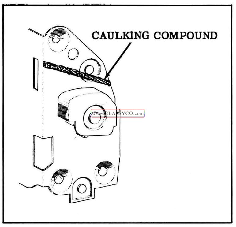
1957 Oldsmobile Door Lock Sealing
REAR DOOR LOCK REMOTE CONTROL ASSEMBLY AND CONNECTING ROD
Remove and Install
- Remove door trim assembly. Detach upper portion of door inner panel water deflector sufficiently to gain access to remote control attaching screws.
- Remove remote control attaching screws and remove remote control from connecting rod. (See Fig. 17-60 and 17 -62)
- a. To remove remote control connecting rod on 4 Door Holiday rear doors, detach rod from clip on inner panel; then detach rod from door lock connector. (See Fig. 17 -60)
b. To remove remote control connecting rod on 4 Door Sedan rear doors, disengage spring clip and detach rod from door lock and clip on inner panel (See Fig. 17 -62) - To install door lock remote control and connecting rod, reverse removal procedure.
NOTE: Adjust remote control rearward. sufficiently to take up slack in linkage.
REMOTE CONTROL ADJUSTMENTS
- Remove door trim assembly. Detach upper portion of door inner panel water deflector sufficiently to gain access to remote control attaching screws.
- Loosen remote control attaching screws. (See Fig. 17-60) Move remote control to forward position; then adjust remote control rearward sufficiently to take up slack in linkage.
NOTE: Check operation of door lock before resealing inner panel water deflector.
REAR DOOR INSIDE LOCKING ROD, LEVER, AND CONNECTING ROD-(4 Door Holidays)
Remove and Install
- Remove door trim assembly. Detach upper portion of inner panel water deflector sufficiently to gain access to inside locking rod, lever, and connecting rod.
- Remove inside lock in rod lever attaching screw (See Fig. 17 -60), and remove lever spring washer and cup washer. Detach inside locking connecting rod from clip on inner panel; then detach lever from inside locking connecting rod and remove lever and inside locking rod from door.
- Detach inside locking connecting rod from door lock connector and remove from door.
- To install inside locking rod, lever, and connecting rod, reverse removal procedure.
NOTE: Check all operations of door lock before installing inner panel water deflector, door trim assembly, and inside hardware.
REAR DOOR OUTSIDE HANDLE
Remove and Install
- Raise door window. Remove door trim assembly and detach upper portion of inner panel water deflector sufficiently to gain access to access hole for door outside handle attaching screws.
- Through access holes for door outside handle attaching screws, (See Figs. 17-60 and 17 -62) remove handle attaching screws; then remove handle and handle gaskets.
- To install rear door outside handle, reverse removal procedure, making sure front and rear gaskets are installed between handle and door outer panel.
NOTE: Adjust (turn in or out) the outside handle push button shaft to provide between 1/32″ and 1/8″ free travel of push button. Check all operations of door lock before installing door inner panel water deflector, door trim assembly, and inside hardware.
REAR DOOR OUTSIDE HANDLE
Disassembly and Assembly
- Remove rear door outside handle.
- Remove spring retainer, stop washer retainer, stop washer, spring, push button and shaft, and sealing washer.
- To assembly rear door outside handle, reverse disassembly procedure. Fig. 17 -65 shows the handle assembled.
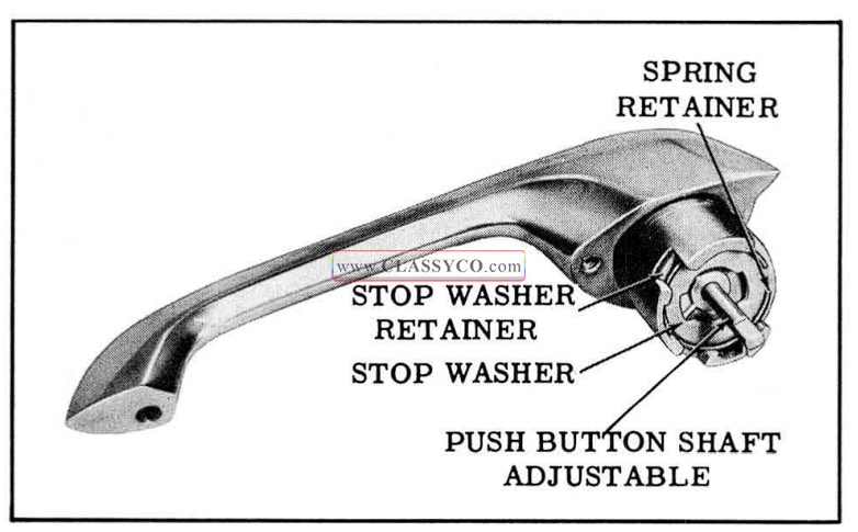
1957 Oldsmobile Rear Door Outside Handle Assembly
NOTE: When installing the handle assembly to the door, adjust the push button shaft to provide between 1/32″ and 1/8″ free travel of the push button.
Check all operations of door lock before installing door inner panel water deflector, door trim assembly, and inside hardware.
REAR DOOR LOCK FREE-WHEELING ADJUSTMENT
When the inside locking rod is in the down position a n d the lock is set in free-wheeling, it prevents the door from being opened by the operation of the inside handle.
The tool required to perform the free-wheeling adjustment can be made from a piece of rod ap proximately 1/8″ in diameter. To make tool, cut rod to approximately 7 ” length, then bend 3/8″ of rod at one end to form a right angle. The rear door lock may be adjusted “in ” or “out” of free wheeling as follows:
- Lower door window; pull inside locking rod knob to “up” position and remove rear door lock upper attaching screw.
- Insert adjusting tool through screw hole. (See Fig. 17 -66)
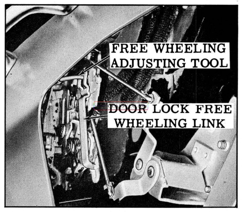
1957 Oldsmobile Rear Door Lock Free Wheeling Adjustment
- While observing through the window opening, with the aid of a light, engage hooked end of adjusting tool in cut -out of free-wheeling link, as shown in Fig. 17 -66. Pull link REAR WARD to set lock “OUT” of free – wheeling and push link FOR WAR D to set lock “IN ” freewheeling.
NOTE: Check all operations of door lock after making a freewheeling adjustment.
CENTER PILLAR TRIM-(4 Door Holidays)
The center pillar tri m material is cemented to the center pillar. The material is covered a long the front and rear edges by pinchweld finishing moldings, and over the top by a pinch weld finishing cap. Each molding is secured to the carpet support by 1 screw, while the finishing cap is secured to the top of the assembly by 2 screws. Prior to installation the underside of the finishing cap is sealed at the outboard portion of the cap.
CENTER PILLAR FINISHING CAP
Remove and Install
- Remove 2 screws from top of cap and remove cap from center pillar.
- To install, first apply sealer to underside of cap as shown in Fig. 17 -67; then position cap on center pillar and install 2 attaching screws.
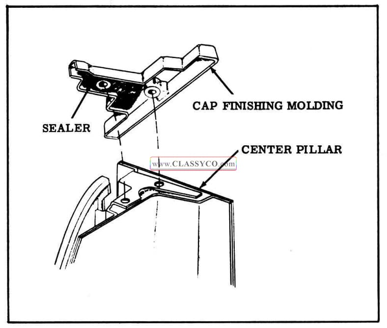
1957 Oldsmobile Sealing Center Pillar Cap Finishing Molding
CENTER PILLAR FRONT AND REAR PINCHWELD FINISHING MOLDINGS
Remove and Install
- Remove center pillar finishing cap.
- Turn back carpeting at base of pinch weld and remove screw securing end of finishing molding to carpet support. Then carefully remove molding from pinch weld flange.
- To install molding, position molding to pinchweld flange and slide molding over flange.
- Install molding attaching screw at lower end of molding, replace carpet, and install center pillar finishing cap.
CENTER PILLAR TRIM ASSEMBLY
Remove and Install
- Remove center pillar finishing cap and front and rear pinch weld finishing moldings.
- Starting at sides of trim assembly carefully break cement bond between trim assembly and center pillar and remove trim assembly.
- To install trim assembly, clean cementing surface on center pillar to insure a smooth cementing surface.
- Apply an approved trim cement to back of trim assembly. Position foundation portion of trim assembly along crown of center pillar to floor pan brace and cement trim assembly in place.
NOTE: Make certain edges of trim assembly are properly cemented around pinchweld flanges to allow installation of pinchweld finishing moldings
- Install pinchweld finishing moldings and center pillar finishing cap.
CENTER PILLAR TRIM-(4 Door Sedans)
The center pillar trim panel assembly is re moved and installed in the same manner as on previous styles. The panel assembly is secured to the center pillar inner panel by ratchet nails.
Remove and Install
- With a flat-bladed tool, carefully pry center pillar trim panel assembly to disengage ratchet nails from center pillar and remove assembly.
- To install, position center pillar trim panel assembly to center pillar inner panel and drive nails into fasteners with a rubber mallet.
NOTE: Prior to installation check nails. Replacement nails are available as a service part.
REAR QUARTER ASSEMBLY
REAR QUARTER BELT FINISHING MOLDING (2 Door Sedans, Holiday Coupes)
Remove and Install
- Remove rear seat cushion and seat back.
- Remove belt finishing molding attaching screws and remove molding.
- To install, reverse removal procedure.
REAR QUARTER BELT FINISHING MOLDING (Convertible)
Remove and Install
- Lower folding top.
- Remove molding attaching screws and remove molding.
- To install, reverse removal procedure.
REAR QUARTER TRIM ASSEMBLY (2 Door Sedans)
Remove and Install
- Remove rear seat cushion and back.
- Remove rear quarter belt finishing molding.
- Remove window regulator handle.
- Remove arm rest assembly.
- Remove drive nail from rear of trim panel.
- Loosen trim assembly nails from body lock pillar nailing strip and remove trim assembly.
- To install, reverse removal procedure.
REAR QUARTER TRIM ASSEMBLY (Convertible)
Remove and Install
- Remove rear quarter belt finishing molding.
- Remove folding top compartment side trim panel.
NOTE: On styles with manually-operated windows, remove window regulator handle and anti-friction washer.
- Swing rear of quarter trim assembly forward. Remove tacks at front and remove assembly.
- To install, reverse removal procedure.
REAR QUARTER TRIM ASSEMBLY (Holiday Coupe)
Remove and Install
- Remove rear seat cushion and seat back.
- Remove belt finishing molding.
NOTE: On styles with manually-operated windows, remove rear quarter window regulator handle and anti-friction washer.
- Remove arm rest assembly.
- Remove drive nail at rear of trim assembly and swing assembly forward to gain access to front attaching tacks.
- Remove front attaching tacks and remove trim assembly.
- To install, reverse removal procedure.
REAR QUARTER ARM REST-(2 Door Sedans) Remove and Install
- Remove arm rest attaching screws and remove arm rest.
- To install, reverse removal procedure.
REAR QUARTER ARM REST ASSEMBLY (Holiday Coupes)
Remove and Install
- Remove rear seat cushion and seat back.
- Remove arm rest attaching screws at front and rear of assembly.
- Disconnect electrical leads as required and remove arm rest.
- To install, reverse removal procedure.
FOLDING TOP COMPARTMENT SIDE TRIM PANEL-(Convertible)
Remove and Install
- Remove rear seat cushion and seat back.
- Remove attaching screws from front and rear of side trim panel.
- Raise trim panel and move it inboard.
- Disconnect electrical leads as required and remove side trim panel.
- To install, reverse removal procedure.
REAR QUARTER WINDOW SWITCH (Holiday Coupes and Convertible)
Remove and Install
- Remove rear quarter arm rest assembly on Holiday Coupes. On convertible styles, remove folding top compartment side trim panel.
- Disconnect switch terminal block from switch assembly.
- Depress spring clips on each side of switch and remove switch and escutcheon as an assembly.
- To remove switch from escutcheon, depress switch retaining springs at ends of switch.
- To install, reverse removal procedure. (See Fig. 17-68)
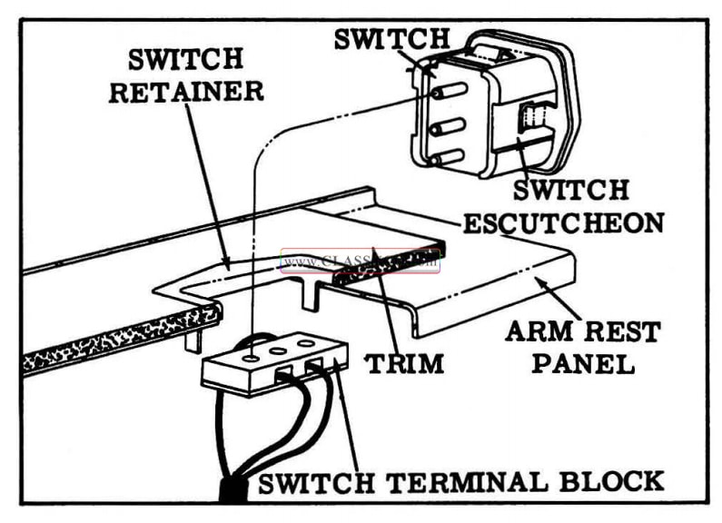
1957 Oldsmobile Rear Quarter Window Switch
REAR QUARTER WINDOW-(2 Door Sedans) Remove and Install
- Remove rear quarter arm rest and trim assembly.
- Remove access hole cover.
- With window raised, remove lower sash channel attaching screws through upper access holes, and disengage lower sash channel from cam channel.
- Carefully lower and rotate window and remove.
- To install, reverse removal procedure. (See Fig. 17 -69)
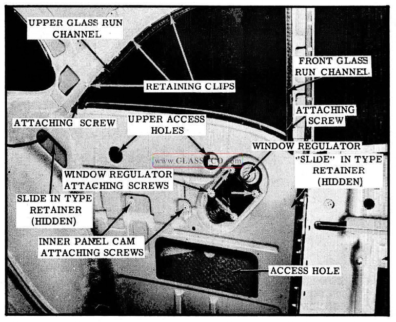
1957 Oldsmobile Rear Quarter Window Installation 2 Door Sedan
REAR QUARTER WINDOW, MANUAL AND ELECTRIC-(Holiday Coupes)
Remove and Install
- Remove rear quarter arm rest and trim assembly and belt finishing molding.
- Remove access hole cover.
- With window in “up” position, remove rear guide attaching screws and remove rear guide.
- Carefully lower window to disengage regulator lift arm from window lower sash channel.
- Disconnect battery positive cable.
- Disengage window front roller from front guide and remove window from body.
- To install, reverse removal procedure. (See Fig. 17-70)
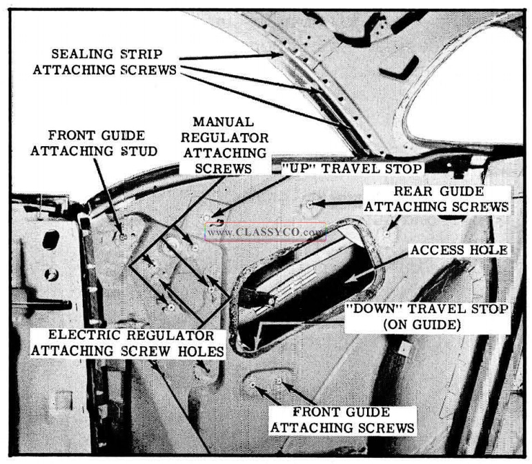
1957 Oldsmobile Rear Quarter Window Installation-Holiday Coupe
Adjustment
- Remove rear quarter arm rest and trim assembly.
- To adjust rear quarter window “fore or aft”, loosen front and rear guide attaching screws, adjust quarter window as desired and tighten guide attaching screws.
- To adjust rear quarter window “in or out” at lock pillar, loosen front guide upper attaching nut, turn adjusting stud in or out as desired and tighten attaching nut.
- To adjust rear quarter window “up” travel, when upper travel limits are reached, loosen “up” stop attaching screw. Adjust stop as desired and tighten attaching screw.
- Remove access hole cover. To adjust rear quarter window “down” travel when lower travel limits are reached, loosen “down” stop attaching screw at lower area of front guide; Adjust “down” stop as desired, and tighten attaching screws. (See Fig. 17-70)
REAR QUARTER WINDOW, MANUAL AND ELECTRIC-(Convertible)
Remove and Install
- Remove rear seat cushion and seat back, and lower folding top.
- Regulate window to half-down position. On styles with power windows, disconnect batter y positive cable to prevent accidental operation of quarter window.
- Remove rear quarter belt finishing molding, folding top compartment side trim panel, and inside handle on manual styles.
- Swing rear quarter trim panel from rear quarter inner panel to gain access to pivot bolt and remove pivot bolt.
- Remove access hole cover.
- Disengage window male hinge from female hinge plate by raising front of window. Then raise window to disconnect lower sash channel cam from window regulator and remove window.
- To install, reverse removal procedure.
CAUTION: Do not operate regulator motor after window is disengaged from regulator. Operation. of motor with load removed may damage unit. (See Fig. 17-71)
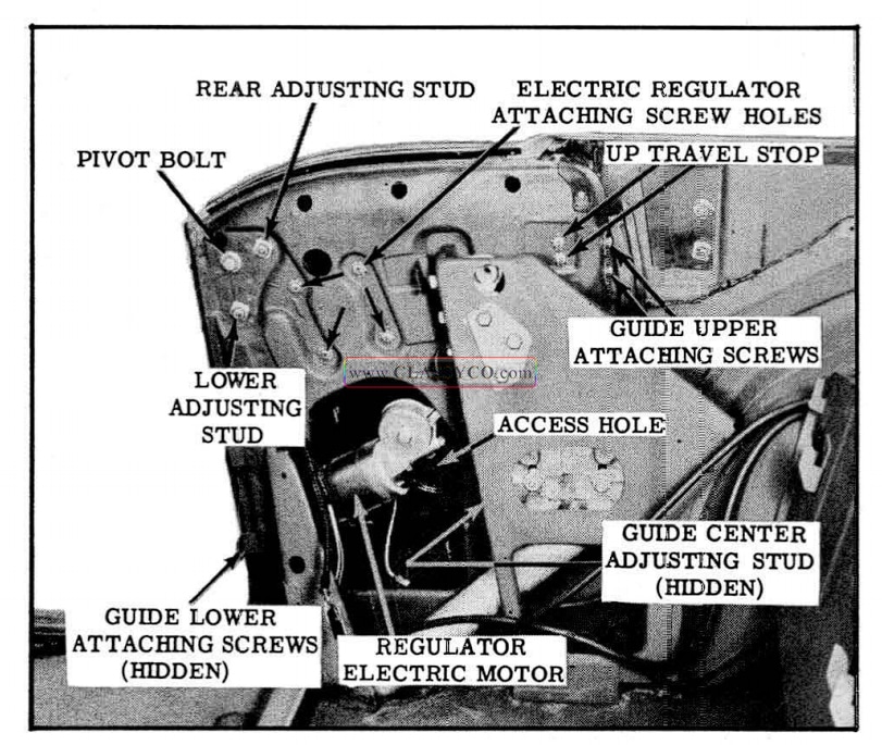
1957 Oldsmobile Rear Quarter Window lnstallartion – Convertible
Adjustment
- Remove folding top compartment side trim panel and turn trim panel away from inner panel to gain access to pivot bolt and adjusting studs.
- To adjust rear quarter window “up or down ” or “fore or aft”, loosen pivot bolt and adjusting stud nuts. Position window where desired and tighten pivot bolt and adjusting stud nuts.
- To adjust top of quarter window ”in or out” when raised, loosen pivot bolt and adjusting nuts. Turn lower adjusting stud in or out until the desired adjustment is attained and tighten bolt and nuts.
- To adjust rear of quarter window “in or out” when lowered, loosen pivot bolt and adjusting nut. Turn rear adjusting stud in or out until the desired adjustment is attained and tighten bolt and nuts.
- To adjust quarter window “up” travel when upper travel limits are reached, loosen “up” stop attaching screws. Move stop up or down as desired and tighten stop attaching screws.
NOTE: In connection with preceding adjustments, it may be necessary to adjust rear quarter window guide. To adjust guide: loosen guide upper, center and/or lower attachments; adjust guide to desired location and tighten guide attachments. (See Fig. 17-71)
REAR QUARTER WINDOW REGULATOR, MANUAL AND ELECTRIC-(Holiday Coupes)
Remove and Install
- Remove rear quarter arm rest and trim assembly and belt finish molding.
- Remove access hole cover.
- On electric regulators, disconnect motor leads from wire harness. Disconnect front guide at lower attachment. Remove regulator attaching screws, disconnect regulator from lower sash channel cam, and remove regulator through access hole.
- On manual regulators, remove rear quarter window and disconnect front guide at upper attachment. Remove regulator attaching screws and remove regulator through access hole.
- To install, reverse removal procedure. (See Fig. 17 -70)
NOTE: The procedure for removing the electric motor from the rear quarter window regulator is the same as outlined for the front door window electric regulator.
REAR QUARTER WINDOW REGULATOR, MANUAL AND ELECTRIC-(Convertible)
Remove and Install
- Remove rear quarter window.
- On styles with electric regulators, disconnect motor leads from wire harness.
- Remove regulator attaching screws and remove regulator through access hole.
- To install, reverse removal procedure. (See Fig. 17-71)
NOTE: The procedure for removing the electric motor from the rear quarter window regulator is the same as outlined for the front door window regulator.
REAR QUARTER WINDOW REGULATOR (2 Door Sedans)
Remove and Install
- Remove rear quarter trim and arm rest assembly.
- Remove access hole cover.
- Remove regulator cam to lower sash channel attaching screws.
- Prop glass in full up position.
- Remove rear quarter inner panel cam.
- Remove rear quarter window regulator attaching screws and remove regulator and regulator cover plate.
- To install, reverse removal procedure. (See Fig. 17 -69) Check for proper installation of run channel in “slide-in” type retainer at lower end.
REAR QUARTER WINDOW FRONT GUIDE (Holiday Coupes)
Remove and Install
- Remove rear quarter window.
- Remove rear quarter window front guide upper attaching nut and lower attaching screws and carefully remove front guide from body through access hole.
- To install, reverse removal procedure. (See Fig. 17-70)
REAR QUARTER WINDOW REAR GUIDE (Holiday Coupes)
Remove and Install
- Remove rear quarter arm rest and trim assembly and belt finish molding.
- Remove access hole cover.
- With rear quarter window in full up position, remove rear quarter window rear guide attaching screws and remove rear guide.
- To install, reverse removal procedure. (See Fig. 17-70)
REAR QUARTER WINDOW GUIDE (Convertible)
Remove and Install
- Remove rear quarter window.
- Remove guide attaching screws at upper and lower attaching points. Lower guide and remove through access hole.
- To install, reverse removal procedure. (See Fig. 17-71)
REAR QUARTER WINDOW GLASS RUN CHANNEL-UPPER AND FRONT (2 Door Sedans)
Remove and Install
- Remove rear quarter belt finishing molding and garnish molding.
- Lower rear quarter window and remove lower attaching screw from upper glass run channel.
- Use a flat bladed tool to disconnect upper glass run channel retaining clips.
- Pull upper glass run channel forward to disconnect channel from lower attachment and remove from body.
- Remove lower attaching screw from front glass run channel and disconnect channel retaining clips.
- Pull front glass run channel upward to disconnect channel from lower attachment and remove from body.
- To install, reverse removal procedure. (See Fig. 17-69)
REAR QUARTER WINDOW SEALING STRIP (Holiday Coupes)
Remove and Install
- Remove rear quarter belt finishing molding.
- Remove sealing strip attaching screws.
- Carefully loosen front end of sealing strip downward with flat bladed tool and pull sealing strip forward to remove from body.
- To install, reverse removal procedure. Seal quarter window sealing strip by applying 3/16″ diameter ribbon of heavy-bodied sealer to top surface of sealing strip along outboard side of attaching holes prior to installation. At front end, seal is to be diverted inboard along front edge.
Adjustments
The rear quarter window sealing strip attaching holes are over-sized to permit “in and out” and “fore and aft” adjustment. To adjust, loosen attaching screws and adjust as required; then tighten screws. (See Fig. 17-70)
REAR QUARTER INNER PANEL SEALING PROCEDURE
Whenever any of the rear quarter inner panel seals are disturbed during service repair operations, it is very important that the affected areas be sealed properly before installation of trim parts.
2 DOOR SEDANS
Each numbered step in the sealing procedure below refers to the corresponding numbered arrow in the illustration. (See Fig. 17-72)
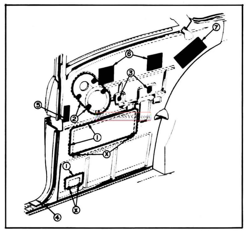
1957 Oldsmobile Rear Quarter Inner Panel Sealing – 2 Door Sedan
- Apply medium-bodied sealer along top and side joints of access hole cover to inner panel. Give special attention to lower corner offsets indicated by arrows marked “X”.
- Apply medium-bodied sealer along entire joint of regulator cover plate to inner panel and over heads of cover plate attaching screws to effect a watertight assembly.
- Apply body caulking compound to inner panel cam attaching holes.
- Apply body caulking compound to opening at joint of rear quarter outer panel and lower forward corner of rear quarter inner panel.
- 6. and 7. Apply waterproof body tape over access holes as shown.
HOLIDAY COUPES
Each numbered step in the sealing procedure below refers to the corresponding numbered arrow in the illustration. (See Fig. 17-73)
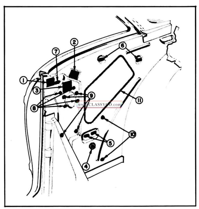
1957 Oldsmobile Rear Quarter Inner Panel Sealing – Holiday Coupe
1, 2 and 3. Apply waterproof body tape over access holes as shown. On manual window styles, apply weatherstrip cement over ex posed surface of regulator spindle hole sealing washer to seal pores of sponge rubber and joint between inner panel and washer.
- On electric window styles, apply medium bodied sealer around grommet and around electric wire at grommet to seal between grommet and inner panel and between wire and grommet. On manual window styles, seal this opening with waterproof body tape.
- Apply body caulking compound to seal window guide attaching holes.
- Apply body caulking compound to seal window guide rear attaching holes.
- Apply body caulking compound to seal window guide front attaching slot.
- Apply body caulking compound to seal manual window regulator attaching holes.
- Apply body caulking compound to seal electric window regulator attaching holes.
- Apply body caulking compound to seal electric wiring clip attaching holes.
- After assembly of access hole cover apply medium-bodied sealer completely around joint of cover and inner panel to effect a watertight seal.
CONVERTIBLE
Each numbered step in the sealing procedure below refers to the corresponding numbered arrow in the illustration. (See Fig. 17 -74)
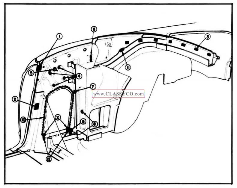
1957 Oldsmobile Rear Quarter Inner Panel Sealing – Convertible
- and 2. Apply waterproof body tape over access holes as shown.
- Use weatherstrip cement to cement rear belt rail trim stick fillers to body. Seal around trim stick attaching holes with cement before installing fillers.
- Apply body caulking compound to seal window regulator attaching holes.
- On manual window styles, apply weatherstrip cement to exposed surface of regulator spindle hole sealing washer. Cement is required to seal pores of sponge rubber and joint between inner panel and washer.
On electric window styles, apply waterproof body tape over window regulator spindle hole.
- Apply body caulking compound to seal rear quarter window upper stop attaching slots.
- Apply body caulking compound to seal electric window regulator attaching holes.
- Apply body caulking compound to seal window guide and wiring clip attaching holes.
- On manual window styles, apply medium-bodied sealer to seal joint between sealing plug and inner panel.
On electric window styles, apply medium bodied sealer to seal joints between grommet and inner panel and between wire and grommet.
- Apply medium-bodied sealer to seal joints of access hole cover and inner panel below off set at lower corners.
- Apply medium-bodied sealer along top and side joints of access hole cover to inner panel. Use care to seal offset at lower corners indicated by arrows marked “X”.
- Prior to installation of trim stick support assembly, apply body caulking compound over attaching holes in gutter.
HEADLINING
On 1957 styles the headlining may be held in contour by concealed listing wires or by a combination of concealed listing wires and exposed roof bows. In addition the headlining is secured at the windshield and back window by cement and tacks; along the side roof rail by tacks or a pronged retainer. In the rear quarter area the headlining may be secured by cement or a pronged retainer. Following are the removal and installation procedures covering both the use of concealed listing w1res only and the use of listing wires and exposed roof bows.
HEADLINING ASSEMBLY WITH CONCEALED LISTING WIRES-(88, S88 2 Door Sedans; 88 4 Door Holiday, All 4 Door Sedans)
Remove
- Remove the following hardware and trim assemblies;
a. Rear seat cushion and back.
b. Rear view mirror and support.
c. Sun visor assemblies.
d. Windshield and back window garnish moldings.
e. Dome lamp.
f. Coat hooks.
g. Finishing moldings where present. - Carefully remove all tacks or staples securing headlining at windshield, back window, and at rear quarter window on 2 Door Sedans.
- Where present, carefully disengage headlining from metal prongs at rear quarter.
- Carefully detach cemented edges of headlining from back glass and windshield areas, and at rear quarter area on Holiday Coupes.
- Carefully detach headlining from prongs of metal retainers alongside roof rails.
- Working from front to rear of body, detach headlining listing wires from both right and left side roof rails, gathering or rolling head lining and listing wires to keep headlining clean.
NOTE: Detach listing wire from metal prongs on center roof bow prior to removing listing wire.
- Remove headlining from body and place on a clean bench. If necessary, listing wires may be removed from headlining as a bench operation.
Install
- Install listing wires into headlining listing pockets. Typical listing wire installation is shown at “1” in views “F” and “G”. (See Fig. 17-75)
- Lift entire headlining assembly into body. Starting at rear and working forward, install listing wires to side roof rails. To install listing wires, tilt wire to rear and insert into holes as indicated by “5” in View “C”; then swing wire to upright position and into notch in. side roof rail shown at “2” in View “C” (See Fig. 17-75)
NOTE: At center roof bow, hook listing wire over tabs and secure wire by bending up tabs.
- Center and align headlining relative to wind shield, back window, side roof rails, dome light, and on 2 Door Sedans to the rear quarter window. Then cement and stay-tack headlining material to tacking strips at back window, shown at “3” View “E”, windshield, as shown at “3” in View “B” and on 2 Door Sedan at rear quarter window. (See Fig. 17-75)
- Working from front to rea r, re move all ‘ ‘full ness” and “draws” from headlining material and permanently tack headlining to tacking strips.
NOTE: Make certain sun visor support openings in headlining are aligned with sun visor attaching screw holes.
- Using a headlining inserting tool or similar wide bladed tool, carefully tuck edges of head lining under retainers a long side roof rails as shown at “3” in View “C”. (See Fig. 17-75)
- Secure headlining to prongs in rear quarter area as shown at “4” in View “O” or cement headlining in rear quarter area as required.
- Install all previously removed hardware and trim parts.
1957 Oldsmobile Headlining Assembly with Concealed Listing Wires
HEADLINING ASSEMBLY WITH CONCEALED LISTING WIRES AND EXPOSED ROOF BOWS (S88-98 Holiday Coupes and 4 Door Holidays)
Remove
- Remove the following hardware and trim assemblies:
a. Rear seat cushion and seat back.
b. Rear view mirror and support.
c. Sun visor assemblies.
d. Windshield upper and side garnish moldings.
e. Back window garnish moldings.
f. Side roof rail lamp assemblies or dome lamp assembly.
g. Coat hooks.
h. Side roof rail molding assemblies, where present. - Carefully remove all tacks or staples securing headlining.
- On 4 Door Holidays, at both right and left rear quarter trim panels, remove drive nails securing rear edge of panel and swing panel frontward to expose ends of headlining.
- Carefully detach cemented edges of headlining from back glass and windshield area.
- Loosen screws securing exposed roof bows to side roof rails.
- Working from front to rear of body, detach headlining listing wires and exposed bows from both right and left side roof rails, gathering or rolling headlining, listing wires, and bows to keep material clean.
- Remove headlining from body and place on a clean bench. Listing wires and exposed bows may be removed from headlining material as a bench operation, if necessary.
Install
- Install listing wires in headlining pockets as shown at “2” in View “F” and exposed bows to cardboard foundation strips as shown at “3” in View “G”. Use extreme care when inserting cardboard foundation strips into grooves of exposed bows to prevent damage to headlining material. (See Fig. 17-76)
- Check to see that barrier strips as indicated at “1” in View “G” are securely cemented to deadener over areas where exposed bows will be located; and, if necessary, recement barrier strips using an approved trim cement. (See Fig. 17-76)
- Lift entire headlining assembly into body. Then, starting at rear and working forward, install listing wires and exposed roof bows to side roof rails.
NOTE: Do not tighten roof bow attaching screws. To install listing wires, tilt wire rearward and insert into holes in side roof rail; then swing wire to upright position and into notch in side roof rail as shown at “4” in View “C”. (See Fig. 17 -76)
- Center and align headlining relative to wind shield, back window, side roof rails and, if present, dome lamp opening. Then cement and stay -tack headlining material to tacking strips at back window, shown at “5” in View “E”, and windshield, shown at “5” in View “8”. Stay-tack headlining along side roof rails as shown at “5” in View “C”. (See Fig. 17-76).
- Working from front to rear, remove all “fullness” and “draws” from headlining material and permanently tack headlining to tacking strips.
NOTE: Make certain sun visor support openings in headlining are aligned with sun visor attaching screw holes.
- Adjust roof bows for proper tension on headlining to “fill-out” the material; then tighten bow attaching screws.
- Cement headlining at rear quarter as shown at “6” in View “D”. (See Fig. 17-76)
- Install all previously removed hardware and trim parts.
1957 Oldsmobile Headlining Assembly with Exposed Bows and Concealed Listing Wire
FLOOR MATS
The following points must be observed when installing or aligning floor mats to insure proper floor mat fit and appearance. All alignment operations should be completed before permanently locating mat under sill plates and accelerator rod grommet.
- Check to see that retainer on floor pan is straight up and down. (NOT bent inboard or outboard)
- Remove all excess sealer around retainer area.
- Check to insure that retainer tabs are free of sealer and that entire tab is bent up.
NOTE: If the retainer tabs are broken, a screw should be installed through the retainer to hold the kick pad.
- After above alignment procedure, it may be necessary to relocate the attaching screw in the fiber tab that attaches to the floor pan. When installing this screw, be sure kick pad is held outboard as far as possible.
- Position the upper floor mat edge UNDER the dash insulator mat and be sure floor mat is aligned to fit contour of both cow1 kick pads.
- All wrinkles must be smoothed out by hand over transmission “hump” in floor pan.
- Floor mat must be carefully positioned under accelerator rod, steering column, clutch, and brake pedal grommets. BE SURE ACCELERATOR ROD GROMMET IS COMPLETELY “SNAPPED” INTO RETAINER. If necessary, trim the insulating material on the bottom of the mat a slight amount around the accelerator hole to prevent the retainer from popping off.
- If car is equipped with power brakes, the “bellows” type dust seal must be positioned over retaining flange on power cylinder. THIS IS ESSENTIAL TO PREVENT FOREIGN MATERIAL FROM ENTERING THE POWER CYLINDER. The rubber grommet should then be positioned over the rubber bellows so that the grommet will be held firmly against the mat. Also, the power brake bracket extends down over the lip on the dash mat insulation that retains the upper edge of the floor mat. It will be necessary to slit the lip on either side of the bracket position and place the mat over lip in order for it to fit without wrinkling.
- The sill plate must be removed, the floor mat layed out, and sill plate positioned over the floor mat. Using a suitable punch or ice-pick, punch holes through the floor mat, then install the sill plate attaching screws.
NOTE: The rear mat will also be retained by the sill plate and the front mat should rest ON TOP of the rear mat.
FRONT SEAT ASSEMBLIES AND SEAT ADJUSTERS
REMOVE AND INSTALL
FRONT SEAT ASSEMBLY WITH MANUAL SEAT ADJUSTER
- Operate seat midway between extreme forward and rearward positions.
- Remove seat side panels.
- Loosen sill plates, turn back floor carpet and remove 2 seat adjuster to floor pan bolts from rear of each adjuster.
- On styles with seat back lighter, disconnect lighter wire from feed wire and detach lighter wire from clip on floor pan.
- Pull entire seat assembly rearward to dis engage seat adjuster front legs from attaching brackets and remove seat assembly from body.
- To install, reverse removal procedure.
FRONT SEAT ADJUSTER
- Remove seat assembly from body and place upside down on clean surface.
- Remove adjuster-to-seat bottom frame front and rear attaching bolts.
- With seat adjuster detached from seat bottom frame, the locking rod can be disengaged from seat adjuster.
NOTE: If a new locking rod is installed, remove the slack from rod and its attaching parts by using a suitable tool and crimping rod near right seat adjuster. (SeeFig.17-77) This operation is performed to insure a proper locking and unlocking action of right seat adjuster when operating control handle on left seat adjuster.
- To install, reverse removal procedure.
NOTE: When attaching seat adjuster to seat bottom frame, be sure that right and left sliding mechanisms are in same relative position.
1957 Oldsmobile Locking Rod Installation
FRONT SEAT ASSEMBLY-WITH ELECTRIC HORIZONTAL SEAT ADJUSTER
- Operate seat to extreme forward position.
- Remove seat side panels.
NOTE: When removing left seat side panel detach terminal block from switch before completely removing side panel.
- Under front of seat, disconnect switch control wire harness from adjuster feed wire harness and detach control harness from clip on floor pan.
NOTE: On styles with seat back lighter, disconnect lighter wire from feed wire and detach from clip on floor pan.
- Loosen sill plates and turn back carpeting to expose rear seat adjuster-to-floor pan attaching bolts and remove bolts.
- Pull entire seat assembly rearward to dis engage front legs from brackets, and remove seat assembly from body.
- To install, reverse removal procedure.
NOTE: Make certain ground wire is secured under seat adjuster floor pan bolt. Check operation of seat to extreme limits of horizontal positions.
IMPORTANT: When installing seat assembly in body, carefully align seat adjuster attaching holes with attaching holes in floor pan to prevent possible binding of seat adjuster linkage. Seat adjusters should be parallel when properly aligned.
ELECTRIC HORIZONTAL FRONT SEAT ADJUSTER REGULATOR AND MOTOR ASSEMBLY
- Remove front seat assembly including seat adjusters and regulator assembly from body and place assembly upside down on a clean surface.
- Remove tensioner spring from right seat adjuster.
- Detach regulator motor wires from control harness.
- Using a screw driver, or other suitable tool pry open seat adjuster regulator rear support spring retainer sufficiently to disengage jack screw nut from support. (See Fig. 17 -78)
- Remove seat adjuster motor and regulator support retainer. (See Fig. 17 -78)
- Remove regulator assembly front support pin and remove assembly from seat.
- To install, reverse removal procedure.
NOTE: After installation of seat assembly, check operation of seat to extreme forward and rearward positions.
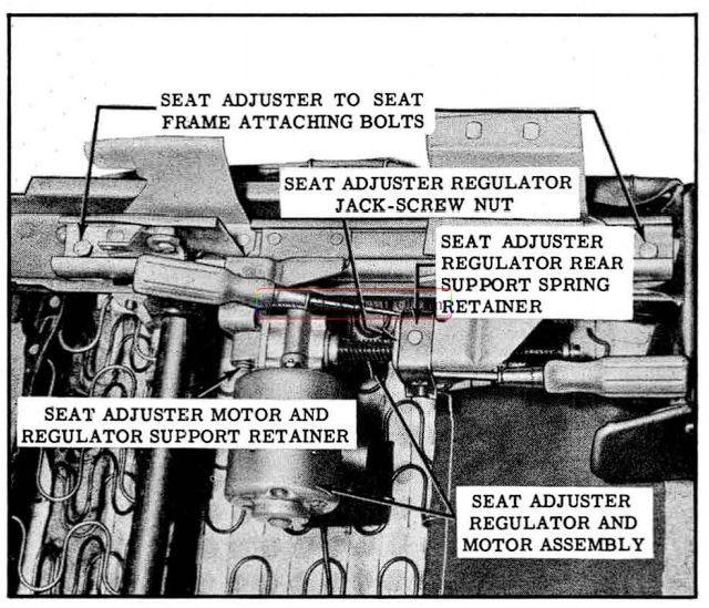
1957 Oldsmobile Electric Horizontal Seat Adjuster (Left)
ELECTRIC HORIZONTAL SEAT ADJUSTER EQUALIZING ROD
- Remove seat assembly (including seat adjusters and regulator assembly) from body and place upside down on a clean surf ace.
- Remove tensioner spring from right seat adjuster and detach jack screw nut from support on left sea t adjuster.
NOTE: If left seat adjuster is being removed, motor and regulator assembly must be removed.
- Position seat adjusters midway between seat adjuster-to-seat frame attaching bolts at front and rear of seat frame, and remove attaching bolts. (See Fig. 17 -78)
- Lift adjuster slightly, then carefully work adjuster outboard to disengage adjuster from equalizing rod and remove from seat frame.
- Equalizing rod may now be removed by disengaging opposite end of rod from support.
- To install, reverse removal procedure.
FRONT SEAT ASSEMBLY-WITH FOUR-WAY OR SIX-WAY SEAT ADJUSTERS
The 4 way seat adjusters are basically the same in design and operation as the 6 way seat adjusters. The rear vertical torque tube (center tube), spinning nut (center nut) and linkage which operate the rear of the seat up and down on 6 way seat adjusters are not used on the 4 way seat adjusters. The rear of the 4 way seat adjusters is operated up and down in unison with the front of the adjusters by means of a connecting link to the front vertical linkage. The 4 way seat adjusters are serviced in the same manner as the 6 way seat adjusters. (See Figs. 17-79 and 17-80)
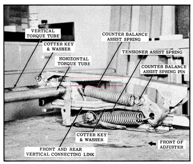
1957 Oldsmobile 4 Way Front Seat Adjuster (Right)
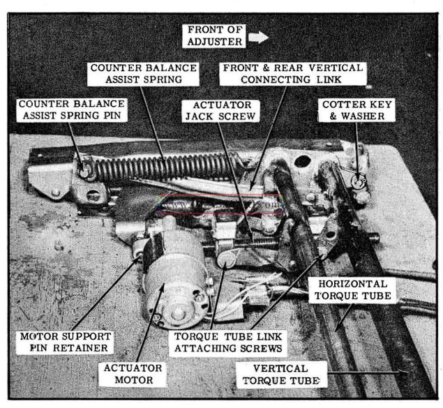
1957 Oldsmobile 4 Way Seat Adjuster (Left)
- Operate seat to raised position and midway between forward and rearward horizontal positions.
- Loosen sill plates and pull back carpeting to expose seat adjuster-to-floor pan attaching bolts.
- Under front of seat, disconnect adjuster control wire harness from adjuster feed wire harness and detach control wire harness from clip on floor pan.
NOTE: On styles with seat back lighter disconnect lighter wire from feed wire connector and detach from clip on floor pan.
- Remove seat adjuster-to-floor pan rear attaching bolts.
- Pull seat assembly rearward to disengage front legs of adjuster from brackets and remove seat assembly including adjusters, and actuator assembly from body.
- To install, reverse removal procedure.
Make sure ground wire is secured under seat adjuster floor pan bolt.
IMPORTANT: When installing seat assembly to body, carefully align seat adjuster attaching holes with attaching holes in floor pan to prevent possible binding of seat adjuster linkages. Seat adjusters should be parallel when properly aligned.
NOTE: After installation of seat assembly check all operations of seat to extreme limit of each position.
FRONT SEAT ASSEMBLY (Less Seat Adjusters and Regulator Assembly)
- Operate seat to fully raised position and mid way between full forward and rearward horizontal positions.
- Remove both right and left sear side pane ls and sea t adjuster jack screw protector cover at front of seat.
- Under front of seat, disconnect control wire harness from adjuster feed wire harness and detach control wire harness from clip on floor pan. Where present, disconnect lighter wire from feed wire.
- At both adjusters remove front and rear seat adjuster-to-seat frame attaching bolts.
- Tilt seat assembly rearward and remove control wire harness from spring clips and retainer along front of seat bottom frame.
- Lift seat assembly (less seat adjusters and actuator assembly) from body.
- To install, reverse removal procedure.
NOTE: After installation of seat assembly check all operations of seat to extreme limit of each position.
FRONT SEAT ADJUSTER (Right or Left)
- Remove seat assembly (including seat adjusters and actuator assembly) from body and place upside down on a clean surface.
- Connect power to control harness feed wire and ground seat frame. On 4-way seats, operate seat adjuster so that seat would be in full up and extreme forward position. On 6-way seats, operate seat adjuster so that front of seat would be down, rear of seat up and seat in extreme forward position.
NOTE: Springs can be removed with adjusters in any position; however, with adjusters positioned as described, springs are under the least tension.
- Remove counter balance assist spring from both seat adjusters and tensioner assist spring from right seat adjuster. (See Figs. 17-81 and 17-82).
- Operate seat adjusters so that both front and rear seat adjuster-to-seat frame attaching bolts (Pigs. 17-81 and 17 -82) are accessible for removal, then disconnect ground wire and control harness feed wire from power source.
- Support equalizing rods on side from which adjuster is being removed to maintain their level position. If removing left adjuster re move retainer securing actuator to support pin. (See Fig. 17-82).
- Remove cotter keys and washers securing torque tube links to adjuster. (See Figs. 17-81 and 17 -82)
- Remove counter balance assist spring pin. (See Figs. 17-81 and 17-82)
- Remove adjuster-to-seat frame attaching bolts.
- Lift adjuster slightly; carefully work adjuster outboard to disengage adjuster from equalizing rods and connecting links. If removing left adjuster carefully disengage actuator unit from support pin. DO NOT OPERATE REGUL ATOR WITH ADJUSTER REMOVED.
- To install seat adjuster, reverse removal procedure.
IMPORTANT: When installing seat assembly in body, carefully align seat assembly so that seat adjuster attaching holes are in line with attaching holes on floor pan to pr event possible binding of seat adjuster linkage. After installation of seat assembly check all operations of seat to extreme limit of each position.
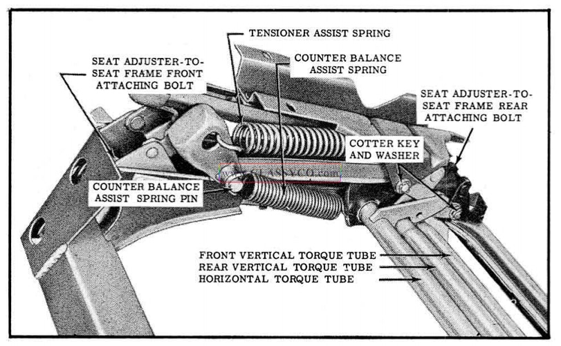
1957 Oldsmobile 6 Way Adjuster (Right)
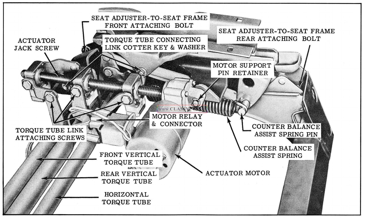
1957 Oldsmobile 6 Way Seat Adjuster (Left)
SEAT ADJUSTER TORQUE TUBES
Any one or all of the 3 torque tubes may be removed in the following manner:
- Remove right seat adjuster.
NOTE: Before removing adjuster, make certain seat is positioned so that torque tube link-to-spinning nut attaching screws (See Fig. 17 -82) are accessible for removal.
- At left end of torque tube being removed, remove cotter key and washer securing torque tube link to seat adjuster and 2 screws securing torque tube links to spinning nut.
- Carefully disengage torque linkage from left seat adjuster and from actuator assembly and remove from seat.
- To install torque tubes, reverse removal procedure.
IMPORTANT: When installing seat assembly in body, carefully align seat assembly so that seat adjuster attaching holes are in line with attaching holes in floor pan to prevent possible binding of seat adjuster linkage. After installation of seat assembly check all operations of seat to extreme limit of each position.
FRONT SEAT ADJUSTER ACTUATOR ASSEMBLY
- Remove front seat assembly (including seat adjusters and actuator assembly) from body and place upside down on a clean surface.
- Remove left seat side panel.
- Connect power to control harness feed wire and ground seat frame. On six-way seats, operate seat adjusters so that front of seat would be down, rear of seat up, and seat in full forward position. On four-way seat, operate seat adjusters so that seat would be in full up and extreme forward position.
- Remove counter balance assist spring from both seat adjusters and tensioner assist spring from right seat adjuster. (See Fig. 17-81)
NOTE: Springs can be removed with adjusters in any position; however, with adjusters positioned as described, springs are under the least tension.
- Operate seat adjuster so that all torque tube link-to-spinning nut attaching shoulder screws are accessible for removal, then disconnect ground wire and control harness feed wire from power source.
NOTE: Torque tube link attaching screws can be removed with adjusters in any position; however, with adjusters positioned as de scribed, screws are easier to remove.
- Disconnect the spinning nut solenoid feed wires at connectors and disconnect control harness wires from connector at motor relay. (See Fig. 17-83)
- Remove torque tube link attaching screws securing torque tube links to spinning nuts. (See Fig. 17-82)
- Remove retainer securing actuator to motor support pin, (See Fig. 17-82) then raise actuator jack screw sufficiently to clear torque tube links and remove actuator assembly from motor support pin.
- To install seat adjuster actuator assembly, reverse removal procedure. Connect relay and solenoid wires as indicated in Fig. 17-83. After installation of seat assembly check all operations of seat to extreme limit of each position.
NOTE: If installing new regulator assembly, transfer spinning nuts from old assembly to new assembly.
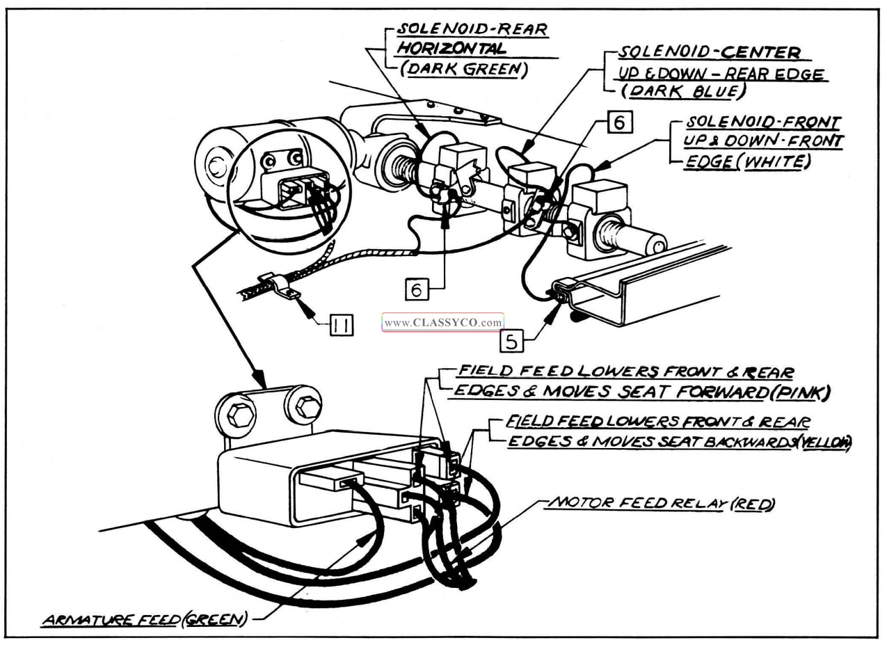
1957 Oldsmobile 6 Way Seat Adjuster Wiring
FRONT SEAT ADJUSTER ACTUATOR SPINNING NUT ASSEMBLY
- Remove seat adjuster actuator assembly.
- As a bench operation carefully drive spinning nut stop pins, shown in Fig. 17-84, out of jack screw.
- Insert a drift punch or a suitable tool into spinning nut frame mounting hole “A”, shown in Fig. 17 -84; rotate spinning nut frame slowly until drift punch engages in locking notch of spinning nut, then unscrew complete spinning nut assembly from jack screw.
- To install spinning nut assemblies, reverse removal procedure.
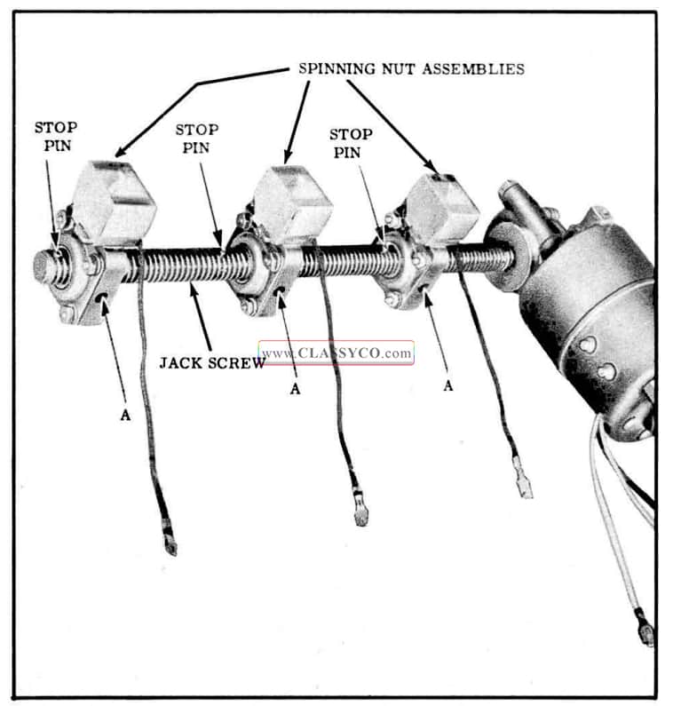
1957 Oldsmobile 6 Way Seat Adjuster Actuator Assembly
IMPORTANT: When installing spinning nut stop pins, install pins so that center of protruding end of pin is located between threads of jack screw. Leave 1/16″ of pin protruding above jack screw threads, as indicated in Fig. 17-85.
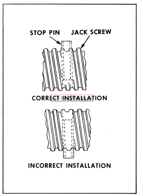
1957 Oldsmobile Jack Screw Stop Pin
FRONT SEAT BACK ROBE CORDS
(Except 98 4 Door Holiday and 4 Door Sedan)
- Inside ash tray, remove 2 screws securing ash tray to seat back frame. Detach ash tray from seat back by raising and pulling outward.
- Remove robe cord and robe cord escutcheon attaching screws, (Fig. 17-86) and remove robe cord and escutcheon from support.
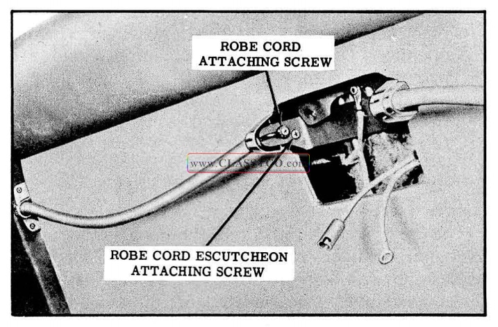
1957 Oldsmobile Robe Cord Installation
- At outer end of robe cord, remove robe cord escutcheon. Move robe cord wire loop rearward and remove through slot in robe cord support. (See Fig. 17-87) Slot extends down ward at left side of seat and upward at right side of seat.
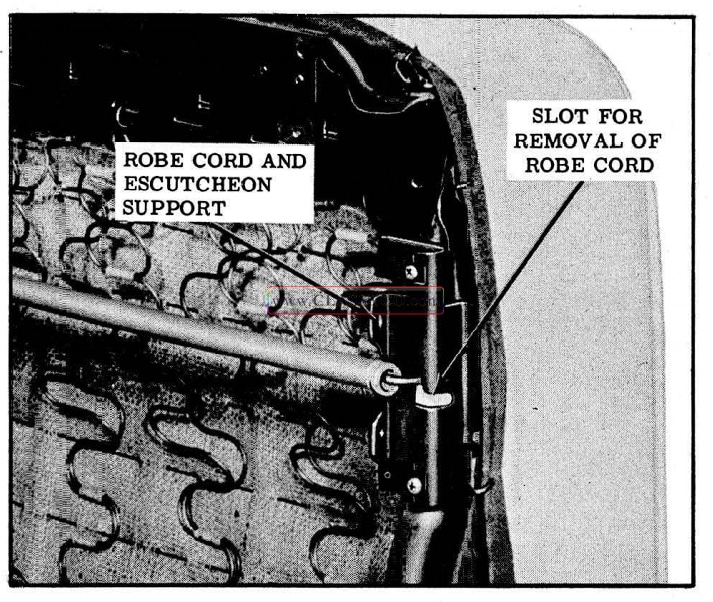
1957 Oldsmobile Robe Cord Attachment
BACK WINDOW ASSEMBLY
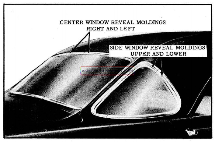
1957 Oldsmobile Back Window Reveal Moldings
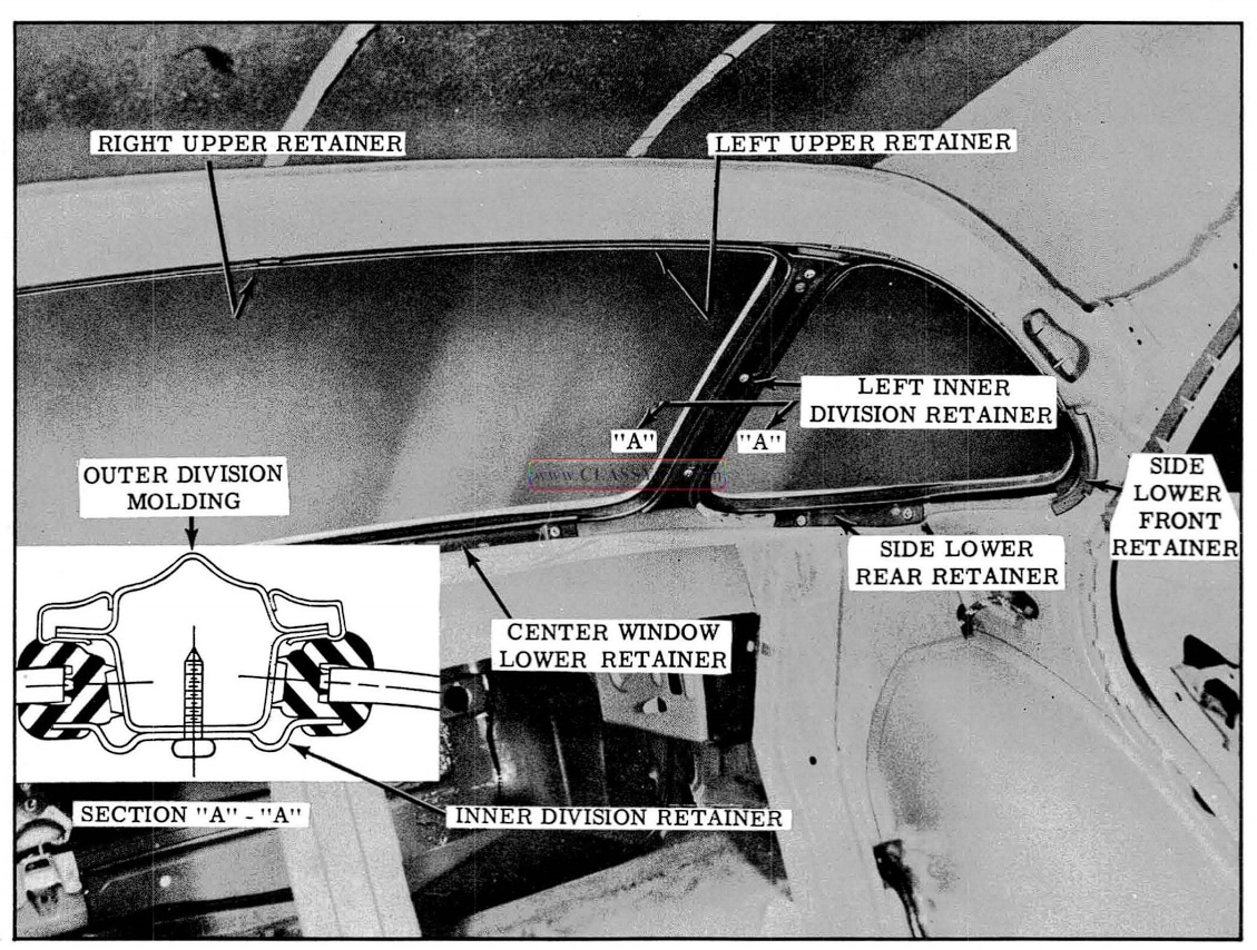
1957 Oldsmobile Back Window Retainers
The back window area is entirely new in design consisting of a center and 2 side glass assemblies. Each assembly, includes a glass and a one-piece rubber channel, and is installed from inside the body into a separate body opening: The assemblies are secured against the pinchweld flange by retainers which are positioned under the inner lip of the rubber channels. The 2 newly designed reveal moldings are installed around each window opening. These “U ” shaped moldings are positioned over the pinchweld flange as shown in Fig. 17-90. The garnish moldings consist of an upper, side, lower, and inner division moldings.
GARNISH MOLDINGS AND BACK WINDOW ASSEMBLIES
Remove
- Place necessary protective covering over interior trim.
- On inside of body remove screws securing back window garnish moldings and remove moldings from body.
- Remove the tacks or staples securing head lining along top and sides of rear window openings and detach headlining sufficiently in rear quarter areas to gain access to all retainer attaching screws.
- At bottom of center window remove screws securing center window lower retainer and remove retainer.
- At each side window remove screws securing side, lower rear, and side lower front retainers; then remove retainers from rubber channel.
- Along top of center window and side windows remove screws securing both right and left upper retainers. Remove retainers from rubber channel.
- At each division channel, remove screws securing division retainer.
- From outside of car, insert suitable flat bladed tool between reveal moldings and channel to break seal.
- Have helper outside of body push each side window assembly and the center window assembly inward, then carefully remove each assembly from body and place on protected bench.
- Remove rubber channel from each glass.
NOTE: To remove any 1 back glass assembly remove only those parts which affect that glass assembly.
Install
- Remove sealer from rabbet of pinchweld flange to insure a clean sealing surface.
- Check each side window drain gutter and drain hose opening for any obstructions and clean out if necessary.
- Using a pressure type gun, apply a bead of medium bodied sealer in corner of rabbet adjacent to pinchweld around each window opening as shown in Fig. 17-90.
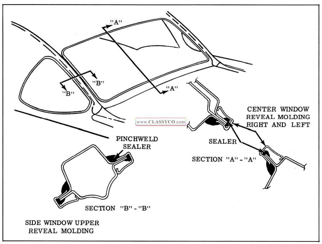
1957 Oldsmobile Back Window Sealing
- Install rubber channel to each glass and firmly press each window assembly into position in body opening to seat assembly and insure proper seal.
NOTE: When installing center window assembly, have helper support glass in window opening until the division retainers are installed.
- Install division retainers and all previously removed parts. Clean off excess sealer and remove protective coverings.
NOTE: When installing retainers make certain retainers are properly positioned under lip of rubber channel(s).
BACK WINDOW REVEAL MOLDINGS
Remove
- Remove back window assembly from affected window opening.
- On side windows, use a suitable tool and carefully disengage formed escutcheon at each end of lower side reveal molding from upper side reveal molding and remove molding from pinch weld flange. Then remove upper side reveal molding.
- At center window use a suitable tool and carefully disengage formed escutcheon at each end of right hand center reveal molding from left molding and carefully remove molding from pinch weld flange. Then remove left hand side reveal molding.
Install
- Clean off pinchweld flange and inside of reveal molding to insure a clean sealing surface.
- Using pressure type gun flow bead of medium bodied sealer in channel of reveal moldings as shown in Fig. 17 -90. Then position moldings over pinchweld with inner edge of channel against pinchweld. (See Section “A-A “, Fig. 17 -90)
- On inside of body apply a bead of medium bodied sealer in corner of rabbet adjacent to pinchweld around entire perimeter of window opening. Install window assembly and all previously removed parts.
- Clean off excess sealer and remove protective covering.
REAR COMPARTMENT
The rear compartment lid hinges, guide, lid lock and cylinder assembly are similar to those used on previous styles. The following new features have been incorporated for the 1957 styles:
- The rear compartment weatherstrip is now secured in the compartment gutter rather than on the compartment lid.
- The Convertible Style incorporates new link type lid hinges to provide the required lid travel.
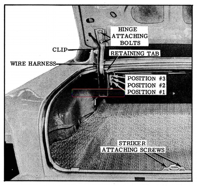
1957 Oldsmobile Rear Compartment
REAR COMPARTMENT LID
The rear compartment lid is secured to the body by 2 hinges which incorporate torque rods to assist in opening the compartment lid and holding it in the “up” position when opened.
Remove and Install
- Open lid and place protective covering along edges of rear compartment opening to prevent damage to painted surface.
- Disengage wire harness from clips on hinge and rear compartment lid inner panel and remove wire harness from lid.
- Scribe location of hinge straps on lid inner panel.
- Remove 2 bolts shown in Fig. 17-91 securing lid to each hinge strap and remove rear compartment lid.
- To install, position lid within scribe marks and reverse removal procedure.
Adjustments
- To adjust compartment lid forward or rearward, or from side to side in body opening, loosen both hinge strap attaching bolts and adjust lid as required; then tighten bolts.
- To adjust compartment lid at hinge area up or down, install shims between lid inner panel and hinge straps as follows:
a. To raise front edge of lid at hinge area, place shim between lid inner panel and forward portion of one or both hinge straps.
b. To lower front edge of lid at hinge area, place shim between lid inner panel and rearward portion of one or both hinge straps. - To check lid lock bolt engagement with striker see “REAR COMPARTMENT LID LOCK STRIKER ENGAGEMENT CHECK”.
- To adjust rear compartment lid guide, loosen attaching screws and adjust guide as required; then tighten screws.
REAR COMPARTMENT LID HINGE
Remove
- Place protective covering over body around upper portion of rear compartment opening and provide support for lid on side where the hinge is to be removed.
- Remove rear compartment trim at hinge area. If left hinge is being removed disengage wire harness from clip on left hinge.
- Scribe location of hinge str ap on lid inner panel and remove bolts securing hinge strap to lid.
- With a suitable length of pipe disengage torque rod from notched retainer on inboard face of opposite hinge box.
NOTE: Mark retainer notch before removing torque rod to insure rod is installed in same position.
- Disengage opposite end of torque rod from lower movable portion of hinge strap and remove rod.
- On all styles except convertibles, bend back tab on inboard face of hinge box at retaining pin location, remove pin and then remove hinge from box.
- On convertible styles, bend back tab on in boar d face of hinge box at each of 2 retaining pin locations, remove pins, and then remove hinge from box.
Install
- Position hinge in box and install hinge pin(s). Bend over retaining tab(s) to secure hinge pin(s).
- Position hinge strap within scribe marks on lid inner panel and install attaching bolts.
- Install “U”-shaped end of torque rod to hinge box making certain outer end of rod is engaged in hole in outboard face of hinge box.
- Engage torque rod to lower movable portion of hinge and engage other end of rod to connect retaining notch on inboard face of opposite hinge box.
- Check alignment of rear compartment lid and make any necessary adjustments.
- Replace wire harness if left hinge was removed. Replace all previously removed trim.
REAR COMPARTMENT TORQUE ROD ADJUSTMENT
The torque rods on the rear compartment lid hinge assemblies can be adjusted to obtain the desired effort required to open and close the lid. With, the torque rod set in Position #1, (See Fig. 17 -92) a decrease in the effort required to open the lid can be had by adjusting the torque rod to Positions #2 or #3. A corresponding increase in the effort required to close the lid results from this adjustment. With the torque rod set in Position #3, a decrease in the effort required to close the lid can be had by adj sting the torque rod to Positions #2 or #1. A corresponding increase in the effort required to open the lid results from his adjustment.
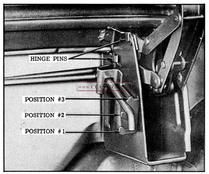
1957 Oldsmobile Rear Compartment Hinge – Convertible
REAR COMPARTMENT LID LOCK
The rear compartment lid lock cylinder, lock and protector cover are located in the rear compartment lid. The rear compartment lid lock striker is located at the rear end panel.
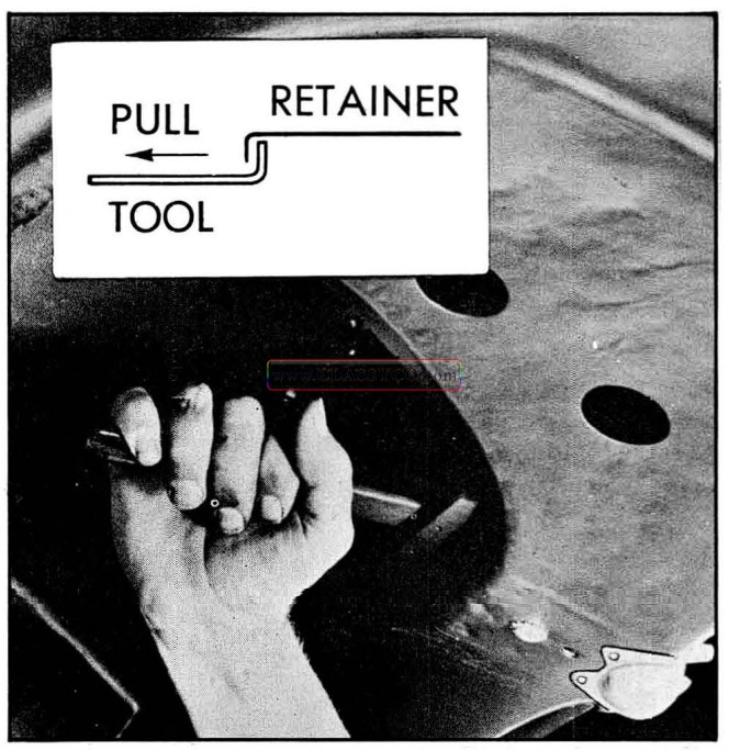
1957 Oldsmobile Rear Compartment Lid Lock Cylinder Removal
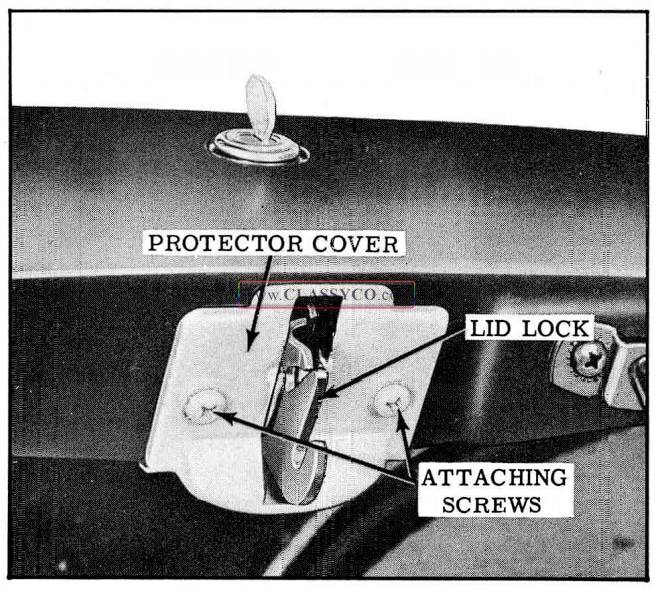
1957 Oldsmobile Rear Compartment Lid Lock and Protector Cover
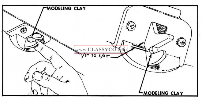
1957 Oldsmobile Rear Compartment Lock Engagement Check
REAR COMPARTMENT LID LOCK CYLINDER
Remove and Install
The key-operated lock cylinder is held to the rear compartment lid outer panel by a sliding retainer located between the lid outer and inner panels.
- Through opening in rear compartment lid inner panel, insert suitable hooked tool to pull the lock cylinder retainer away from lock cylinder.
- Remove lock cylinder and gasket from outer panel of rear compartment lid.
- To install, reverse removal procedure after weather sealing lock cylinder gasket to lid outer panel.
REAR COMPARTMENT LID LOCK AND PROTECTOR COVER
Remove and Install
- Remove rear compartment lid lock cylinder.
- Remove 2 screws securing protective cover to lid inner panel.
- Remove 3 screws securing lock and protective cover to lid inner panel and remove cover and lock.
- To install, reverse removal procedure. Apply medium-bodied sealer to surface of lid lock which contacts lid inner panel.
REAR COMPARTMENT LID LOCK STRIKER
Remove and Install
- Scribe location of striker and remove 2 attaching bolts; then remove striker. (See Fig. 17- 91)
- To install, position striker within scribe marks and reverse removal procedure.
Adjustments
- To adjust striker up or down, loosen attaching bolts, adjust striker as required; then tighten bolts.
- To adjust striker forward, loosen attaching bolts and install emergency spacer between striker and support; then tighten bolts.
REAR COMPARTMENT LID LOCK BOLTS AND STRIKER ENGAGEMENT CHECK
To check the amount of engagement of the rear compartment lid lock bolt with the lock striker, use the following procedure:
- Insert a small quantity of modeling clay at bottom of bolt slot and close lid with a moderate slam.
- Open lid and check amount of engagement of lock bolt with striker as indicated by compression of the clay. With a ruler measure the distance between the base of the “U” in clay to base of “U” in lock bolt. This dimension should be 1/8″ to 5/32″.
- Adjust striker as required and if necessary use a spacer or shim for extreme cases of lid lock striker adjustment. Tighten all attaching screws.
REAR COMPARTMENT WEATHERSTRIP
The weatherseal at the rear compartment is provided by a one-piece weather strip which is secured to the body by the compartment opening gutter. An additional sea l is obtained by application of weatherstrip cement to the rear compartment gutter at the weld joint as shown in Section “C-C” of Fig. 17-96 prior to installation of the weatherstrip.
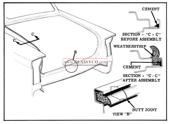
1957 Oldsmobile Rear Compartment Weatherstrip
Remove
- Separate “butt ” ends of weatherstrip at bottom of compartment opening. With flat-bladed tool carefully disengage weatherstrip from its cemented foundation in the gutter across the bottom, up the sides, and across the top. Re move the weatherstrip
Install
- Check gutter around rear compartment opening to make cert a in surface is clean.
- Using a pressure-type gun, flow a bead of weatherstrip cement along weld joint at lower inner corner of the rear compartment gutter around entire perimeter of gutter as shown in “C-C ” Fig. 17-96.
- Center weatherstrip at area between lid hinges, using color identification mark at center of weatherstrip as guide.
- Using a flat-bladed tool, such as putty knife with rounded corners or a headlining inserting tool, insert weatherstrip into gutter across top down sides and across buttom of rear compartment.
- Trim ends of weatherstrip to form “butt ” joint. Brush weatherstrip cement on both ends of weatherstrip and secure ends together as shown in view “B”

1957 Oldsmobile Trim Attachment at Front Roof Rail
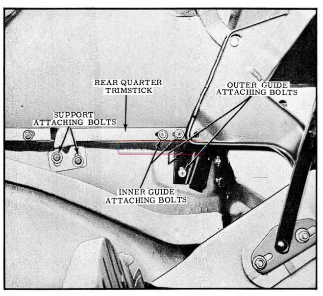
1957 Oldsmobile Rear Quarter Trimstick and Support Assembly
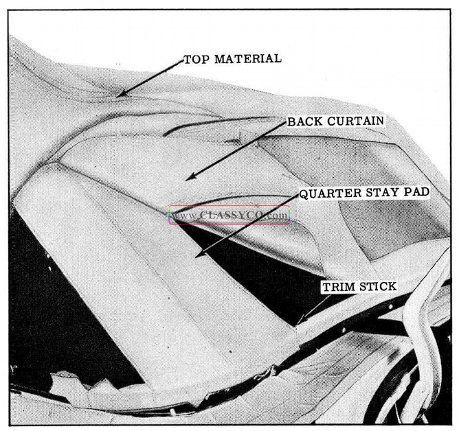
1957 Oldsmobile Convertible Top Rear End
FOLDING TOP ASSEMBLY
The folding top trim on the 1957 Convertible Styles is attached in a manner similar to that used on past models except for the “floating” trim stick at each rear quarter. Due to the new trim stick design, the removal and installation procedure of the top trim in the quarter area is slightly different from the procedure used on past models.
Remove
- Place protective covers on all exposed panels which may be contacted during procedure.
- Remove following trim and hardware items:
- Rear seat cushion and back.
- Folding top compartment side trim (arm rests).
- Side roof rail rear weatherstrip, then loosen top flaps from rail.
- At the front of body, raise front roof rail, remove retainers and front weatherstrip, and detach top material from front roof rail.
- Detach folding top compartment bag from rear seat back panel and attach it to rear roof bow, thus exposing rear trim stick attaching screws and rear quarter trim stick assemblies.
- At each rear quarter area remove bolts and washers securing rear quarter trim stick and support assembly to rear quarter inner panel.
- Remove rear trim stick attaching screws; then lift trim assembly with attached quarter and rear trim sticks on top of rear compartment front panel. Remove nuts and washer securing front inner guide to trim sticks and remove inner guide.
- Remove screw securing escutcheon clip at each end of wire-on-binding on rear bow. Then remove wire-on-binding from rear bow and detach top material, side stay pads, back curtain and quarter stay pads from trim sticks and rear bow; then carefully lower rear bow. The trim sticks, with attached compartment bag, can now be removed from body and placed on clean bench.
- Loosen front end of side roof rail front weatherstrip sufficiently to detach top material flap which is cemented to rail.
- Remove side stay pads attached to front roof rail with tacks and to front and center bows with screws; then lock front roof rail to wind shield header.
Install
- Position rear bow for proper installation by installing spacer sticks as shown in Fig. 17-100.
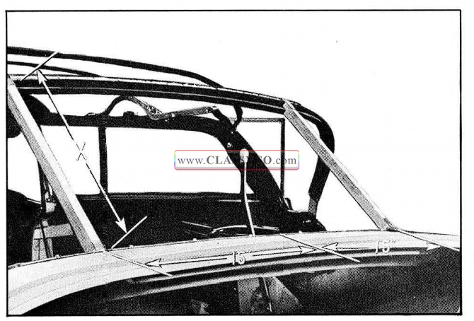
1957 Oldsmobile Rear Bow Positioning
NOTE: The sticks are placed 30″ apart, each being 15″ from the centerline of body. The stick length “X” is approximately 181/2″, and is measured from chrome belt molding to rear rolled edge on tacking strip.
- As a bench operation, tack rear quarter stay pads to large trim stick, as shown in Fig. 17-101.
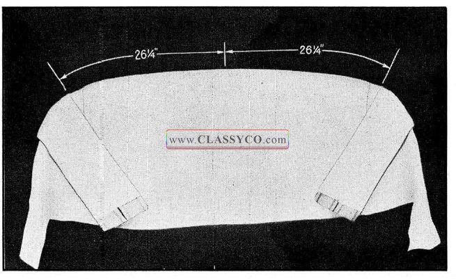
1957 Oldsmobile Tacking Rear Quarter Stay Pads
NOTE: The inner edges of the pads are 26 1/ 4 ” from center of trim stick. Low er edges of pads are set flush with lower edge of trim stick for positive location.
- Center and tack back curtain to trim stick as shown in Fig. 17-102. The short er low er edge of curtain should be set flush with low er edge of trim stick as shown in Fig. 17 -102. Tack curtain to a point opposite outer edges of window and leave outer ends of curtain loose. Tacks should be placed close to each side of ever y screw hole in trim stick. Then pierce back curtain for each screw.
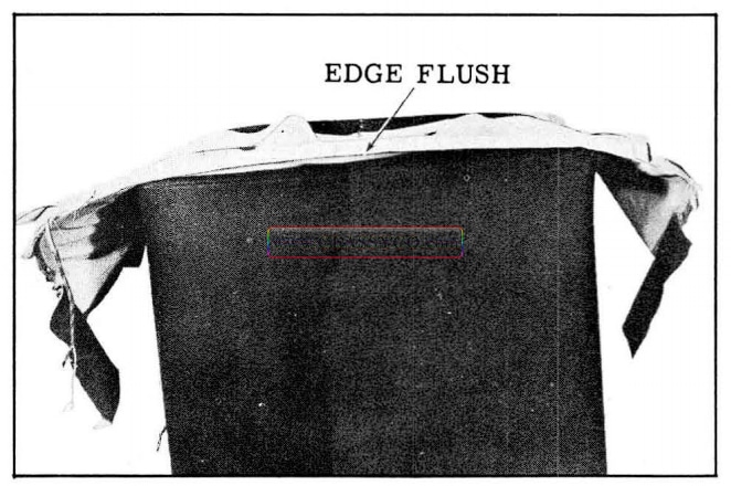
1957 Oldsmobile Tacking Back Curtain
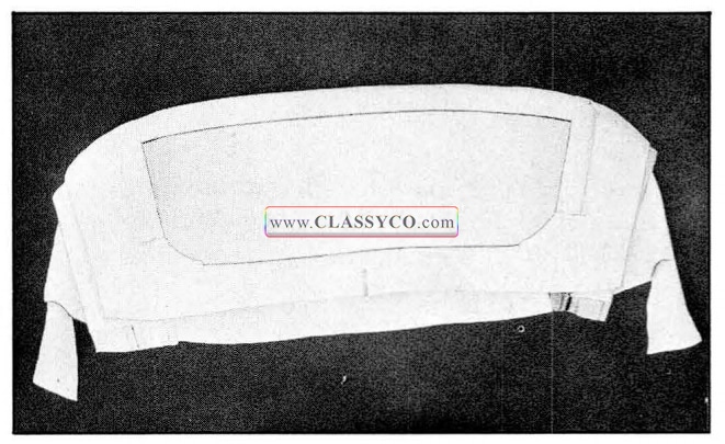
1957 Oldsmobile Back Curtain Assembly
- Inspect rubber trim stick fillers cemented to body below pinchweld as shown in Fig. 17-104. Recement if necessary.
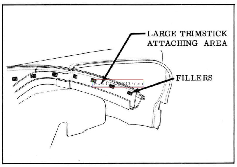
1957 Oldsmobile Trimstick Fillers
- Install center trim stick, with pads and curtain attached, in body. Secure back curtain with one tack in rear bow to prevent damage to plastic sheet. Attach the trim stick, with screws at each end, at the sharp bends and at center. Make sure that each screw is driven completely in to represent finished conditions.
- Tack quarter stay pads to rear bow with inner edges located at the offset in rear bow as shown in Fig. 17-105. Trim off excess material at rear bow.
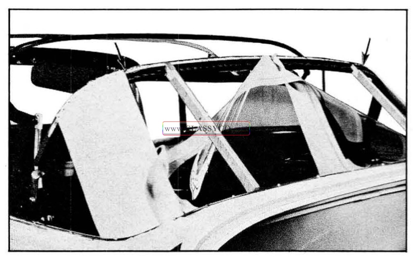
1957 Oldsmobile Pads and Curtain Attachment to Large Trim Stick
- Install side stay pads in the conventional manner. Dimension “Y” in Fig. 17-106 is approximately 17 3/8″ and is measured from the center of each bow at inner edge of the pad.
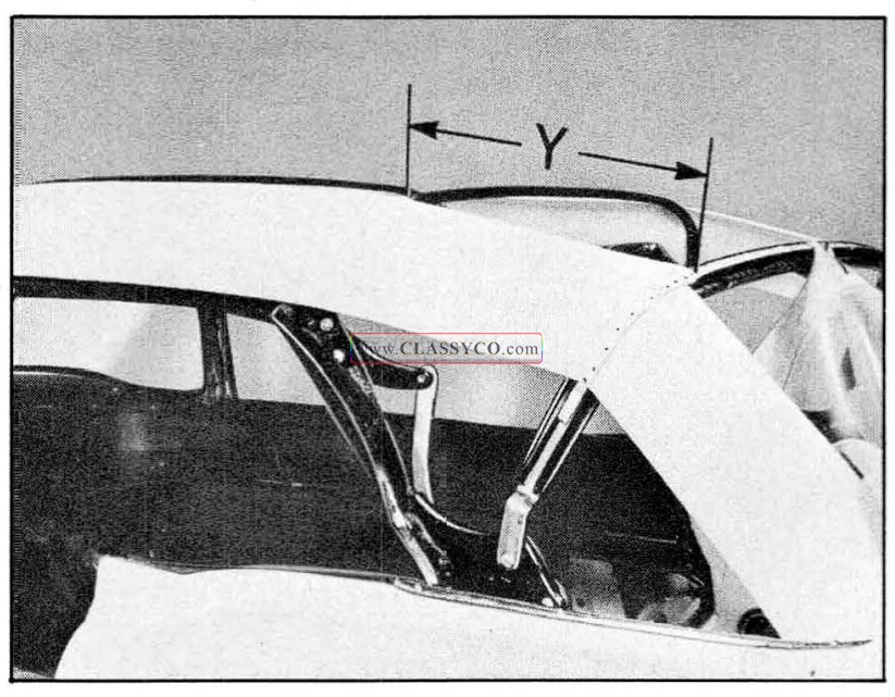
1957 Oldsmobile Positioning of Bows
- Remove spacer sticks when side pads have been installed.
- Tack back curtain to rear bow as shown in Fig. 17-107. Make sure all fullness has been drawn from curtain before trimming off excess at rear bow.
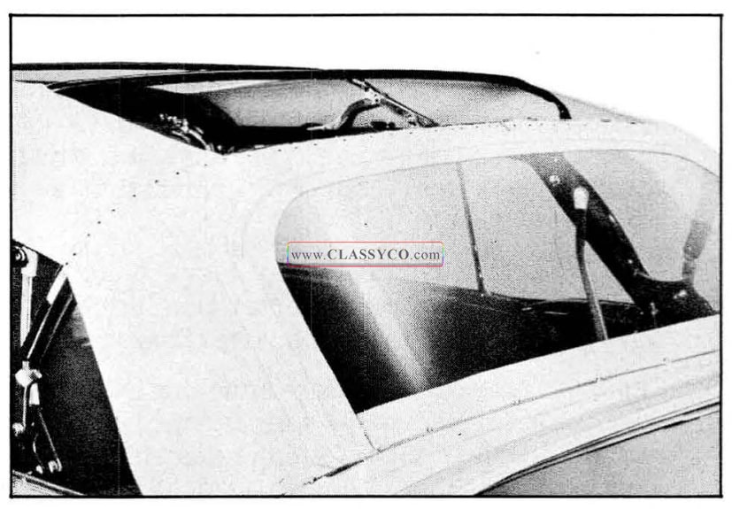
1957 Oldsmobile Tacking Back Curtain (2)
NOTE: It may be necessary to install additional trim stick screws to check the fit of the curtain along belt line.
- As a bench operation, open top material seams as indicated in Fig. 17-108, and carefully apply an approved convertible top fabric sealer along entire length of the seams with a small, pressure-type gun. Note that sealer is applied at two locations along each seam as indicated by two arrows.
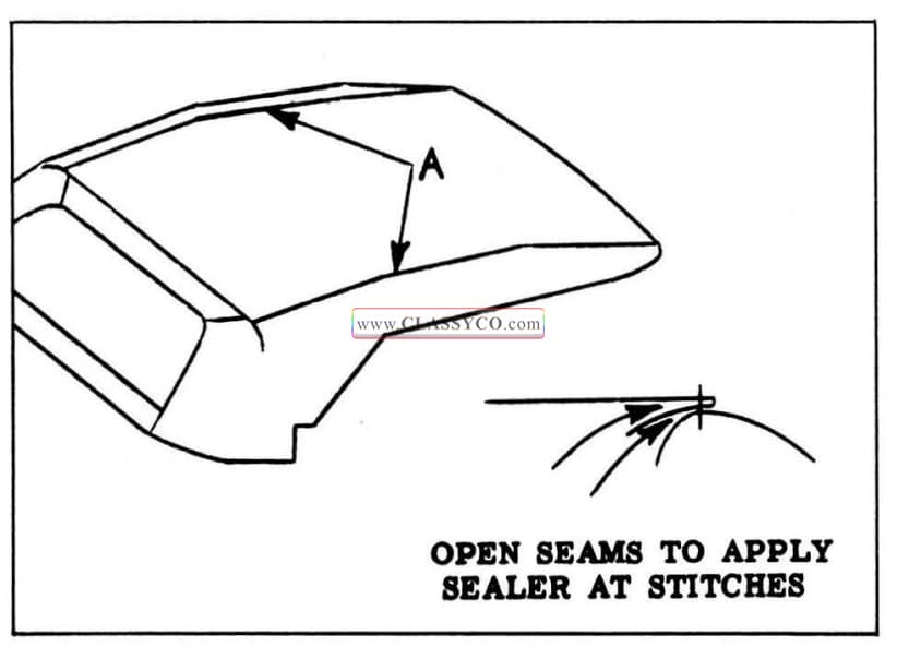
1957 Oldsmobile Convertible Top Sealing
- Position top trim on frame work and center assembly both fore and aft and side to side. Positively locate top by engaging the weather flaps at back curtain and by cementing the quarter flaps to side roof rails. {See Fig. 17-109)
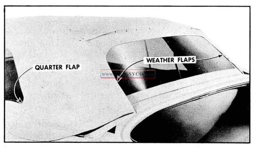
1957 Oldsmobile Installation of Weather Flaps and Quarter Flaps
- Stay-tack top to the rear bow and align and stay-tack the seams on outer ends of rear bow. (See Fig. 17-109)
- At front roof rail, pull top material forward (do not stretch excessively tight) and cement front flaps to the side roof rail. (See Fig. 17-110)
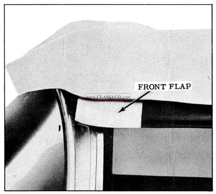
1957 Oldsmobile Cementing Front Flaps
- Remove outer center trim stick screws and install top material into body.
NOTE: Trim stick screws beneath the back window must hold trim stick in position during following operation.
- Inside body draw down outer ends of back curtain and top material. When it has been determined that back curtain and top material are fitting properly together and to chrome belt molding, mark curtain and top as shown in Fig. 17-111 and install enough trim stick screws to maintain position.
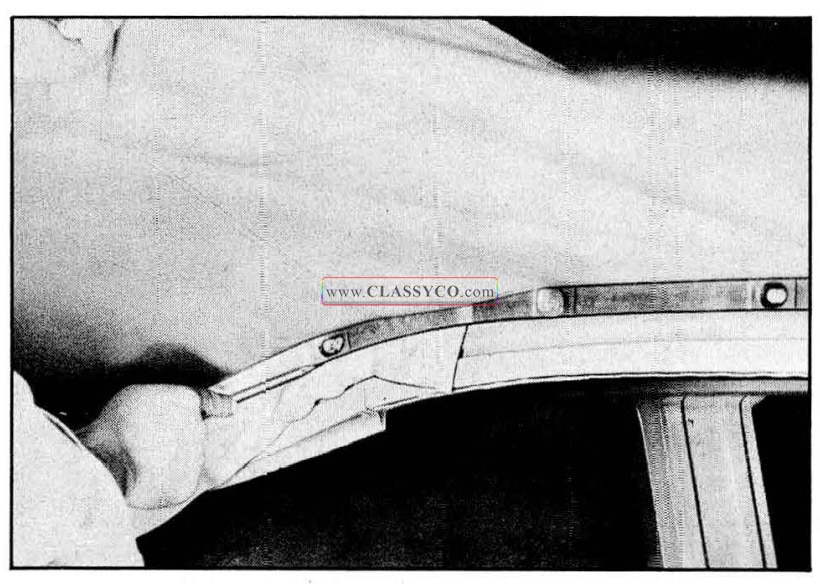
1957 Oldsmobile Positioning Back Curtain
- At the front of body, draw top material forward across front roof rail, which must be locked to windshield header. When most of fullness is removed, mark underside of top material opposite front edge of rail.
- Unlock roof rail and apply trim cement to low er side of rail and to top material which will contact this portion of rail. (See Fig. 17 -97)
- Align and cement the top material to the front roof rail. Lock top and check fit of top material. Make any necessary alterations to the position of the top material at this time.
- Unlock the top and tack the material to rail. (See Fig. 17-97)
- Install front roof rail front weatherstrip and retainers and lock front roof rail.
- Recheck final marked position of back curtain outer ends and top material at rear trim stick. Draw top material to desired tension (not “drum” tight) and tack material to rear bow as shown in Fig. 17-112. Trim off excess material.
NOTE: The tacks outboard of seams should be restricted to a distance not to exceed 6″, which is the length wire-on binding extends past seam.
IMPORTANT: This tacked joint must be sealed with an approved convertible top fabric sealer. Sealer should be applied from outside, as indicated at “A”, and from underside, as indicated at “B”. Sealer should be applied so that it will flow around tacks for proper seal.
- Detach trim stick and tack outer ends of back curtain and top material to stick as shown in Fig. 17 -113. Use marked line as locating reference.
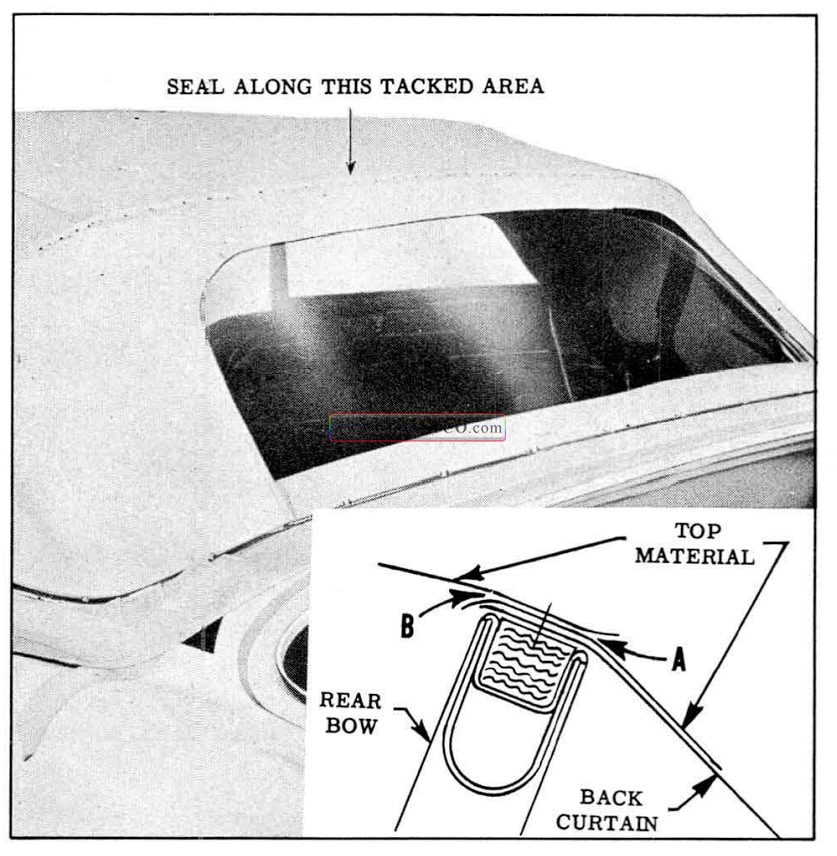
1957 Oldsmobile Sealing at Rear Bow
IMPORTANT: Apply a waterproof sealing tape over tacked edges of back curtain and top material so that after back curtain and top material are trimmed, tape can be wrapped around to cover inside of trim stick. The in set in Fig. 17-113 shows final installation of sealing tape after top installation has been checked and top material trimmed.
- Install trim stick with all screws, and install wire-on binding and clip escutcheons.
- Inside of body, draw quarter section of top material to desired position with short trim stick held in place by hand. Then mark top material in same manner as was done at rear trim stick. (See Fig. 17-111)
- Remove screws at end of rear trim stick to loosen top material in rear quarter area. Then place small trim stick in position along previous marking, roll stick to expose tacking sur f ace, and tack top material to trim stick.
NOTE: Make certain front inner guide attaching holes are at forward end of trim stick.
- Cut holes in top material to conform to holes in t rim stick for front inner guide. Apply sealing tape to tacking surface of small trim stick.
- Position front inner guide on outboard edge of small trim stick and secure in place by 2 nuts and washers. (See Fig. 17-98)
- Insert end of inner guide into outer guide channel and install 2 bolts securing trim stick and support assembly to rear quarter inner panel. Check alignment of top in quarter area and make any necessary adjustments. Install previously removed screws from end of large trim stick. (See Fig. 17 -98)
- When completed, folding top should be free of wrinkles and draws. Check operation and locking action of the top. Following this operation check, trim off excess material below trim sticks.
CAUTION: Do not cut sealing tape during trimming operation.
- Wrap sealing tape around trimmed edges of top material and apply to inside of trim sticks. (See inset in Fig. 17 -113)
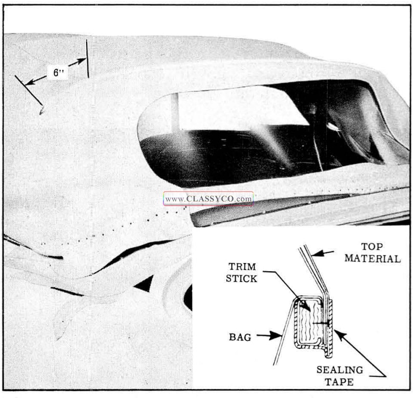
1957 Oldsmobile Top Attachment at Rear Trim Stick
- Install all previously removed trim and hardware and clean any soilage from top material, back curtain or pads.
EXTERNAL TOP INSTALLATION ONLY
Remove and Install
To install the external top material only, remove the material without disturbing the back curtain or stay pads. Then reinstall the replacement top trim as outlined in the installation of the entire top starting with step 10.
BACK CURTAIN ASSEMBLY ONLY
Remove and Install
To install a replacement back curtain, it is necessary to detach the top material from the rear belt Him stick and from the rear bow. By making reference marks on the folding top trim and on the sealing tape along the belt molding, the top material can be returned to its original position with a minimum of refitting.
HYDRO-LECTRIC SYSTEM
The convertible top Hydro-Lectric System is the same as used on past styles except for the installation of the motor and pump assembly. On past styles, the motor and pump unit was installed in a vertical position behind the left side of the rear seat back. On 1957 convertibles, the unit is installed in a horizontal position behind the center of the rear seat back.
Fig. 17-114 shows an exploded view of the motor and pump assembly. The parts indicated by letters are as follows:
A. Motor and Pump End Plate Assembly
B. Sealing Ring
C. Outer Pump Rotor
D. Inner Pump Rotor
E. Rotor Drive Ball
G. Fluid Control Valve Balls
H. Pump Cover Plate Assembly
I. Pump Cover Plate Attaching Screws and Washers
J. Reservoir Tube and Bracket Assembly
K. Reservoir Tube End Plate and Sealing Ring
L. Filler Plug and Sealing Ring
M. Reservoir Bolt, Washer and Sealing Ring Assembly
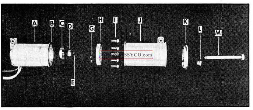
1957 Oldsmobile Motor and Pump Assembly
MOTOR AND PUMP ASSEMBLY
Remove
- Operate folding top to full “up” position.
- Disconnect positive battery cable.
- Place protective covering over rear seat back and cushion.
- Working inside body, detach front edge of folding top compartment bag from rear seat back panel.
- Working on inside of body over the rear seat back, remove pump and motor shield attaching screws and remove shield.
- Remove clips securing the wire harness.
- Disconnect motor leads from the wire harness and remove clips securing hydraulic hose to rear seat back panel.
- To facilitate removal apply a rubber lubricant to pump attaching grommets; then carefully disengage grommets from floor pan. (See Fig. 17-115)
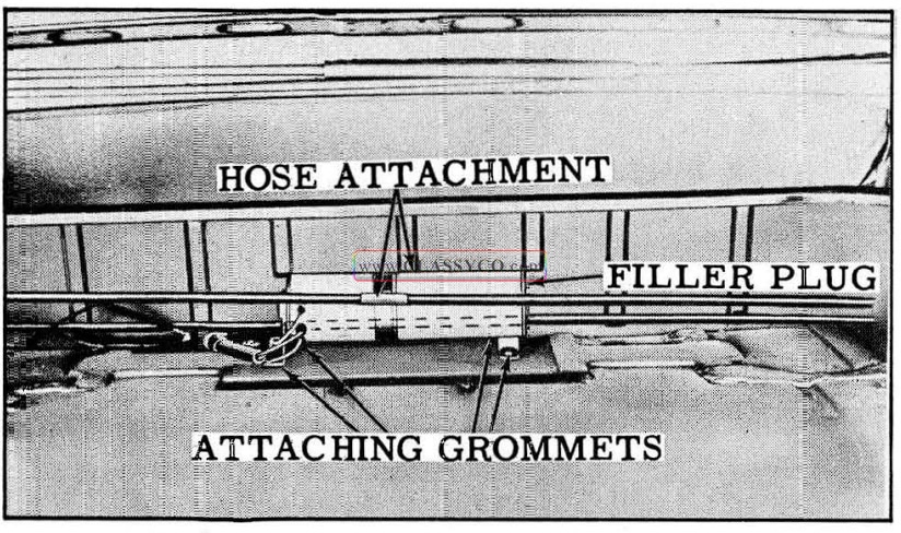
1957 Oldsmobile Motor and Pump Assembly (2)
- Place absorbent rags below hose connections and end of reservoir.
- With a straight-bladed screw driver, vent reservoir by removing the filler plugs; then reinstall plug.
NOTE: Venting reservoir is necessary in this “sealed-in” unit to equalize the air pressure in reservoir to that of atmosphere. This operation prevents possibility of hydraulic fluid being forced und er pressure from dis connected lines and causing damage to trim or body finish.
- Disconnect hydraulic lines from sides of motor and pump assembly, and cap open fittings to prevent leakage of fluid. Use a cloth to absorb any leaking fluid, then remove unit from r ear compartment.
Install
- If a replacement unit is being installed, fill reservoir unit with specified Delco #11 hydraulic fluid (G.M. Hydraulic Brake Fluid Super #11). See “Checking Fluid in Reservoir” for proper fluid level.
- Connect hydraulic hoses, engage attaching grommets in panel and connect wiring.
- Remove reservoir filler plug and place absorbent rags under filler opening.
- Connect battery and operate top through its up and down cycle with filler plug removed from reservoir.
- Check connections for leaks and check fluid level in reservoir. See “Checking Fluid in Reservoir” for proper level.
- install previously removed parts.
DISASSEMBLY AND ASSEMBLY OF RESERVOIR TUBE FROM MOTOR AND PUMP ASSEMBLY
Disassembly
- Remove motor and pump assembly from body.
- Scribe a line across the pump end plate, reservoir tube, and reservoir tube end plate as shown in Fig. 17-116 to insure correct assembly of parts.
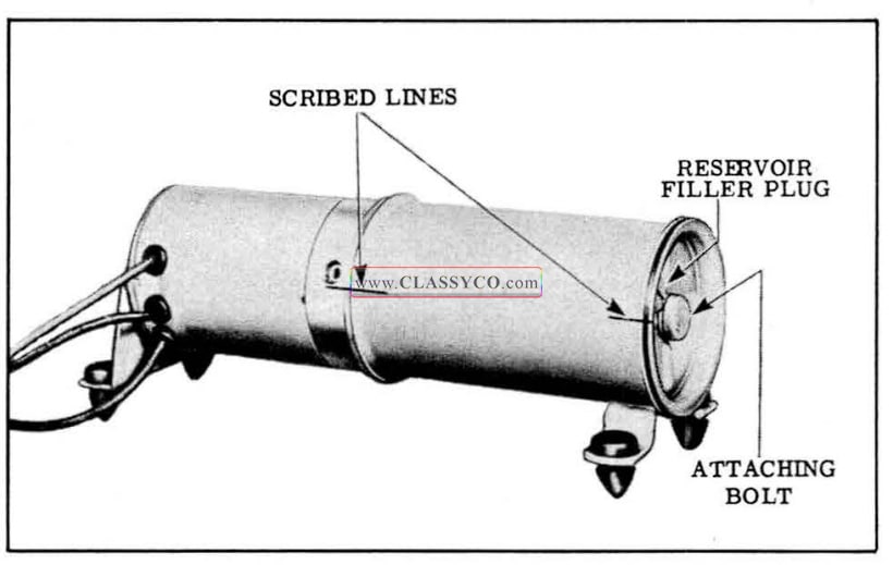
1957 Oldsmobile Motor and Pump Assembly (3)
- With a straight-bladed screw driver, remove reservoir filler plug. Note sealing ring around plug.
- Drain fluid from reservoir into a clean container.
- With suitable tool remove bolt from end of assembly and remove reservoir end plate and tube. Note sealing rings around bolt, reservoir end plate, and between end of reservoir tube and pump assembly.
Assembly
- Position sealing ring on pump and assemble reservoir tube to pump according to scribe marks.
NOTE: Bracket assembly on tube should be located at outer end when tube is assembled to pump.
- Position sealing ring on tube end plate and place end plat e on reservoir tube, lining up the scribe marks. Install and tighten attaching bolt.
- Place unit in horizontal position and fill with fluid until level of fluid is even with bottom of filler plug hole.
- Make sure that sealing ring is on the filler plug, before installing filler plug.
FOLDING TOP LIFT CYLINDER
Remove and Install
- Remove rear seat cushion and seat back.
- Remove folding top compartment side trim panel.
- Remove attaching nut, bolt, bushing, and washer from upper end of cylinder.
- Remove attaching screws from support in lower end of cylinder.
- Move cylinder to gain access to hydraulic hose connections.
- Disconnect and cap hydraulic connections on cylinder and on each hose.
CAUTION: Before disconnecting the hydraulic connections, place suitable wiping rags under the connections to absorb any drippage of hydraulic fluid. Also, disconnect the battery positive cable to prevent the accidental operation of the motor and pump while the hydraulic hoses are disconnected.
- Remove cotter pin, clevis pin, spacer, and support from lower end of cylinder and remove cylinder.
- To install cylinder, reverse removal procedure with following exceptions: To aid in connection of cylinder piston rod to folding top linkage, use power to raise piston rod to ex tended position. Operate top down and up several times, then check and correct level of hydraulic fluid in reservoir.
OPERATION OF THE FOLDING TOP
The principles of top operation are the same as on previous models. When the control switch is pushed upward, the battery feed wire is connected to the red motor lead and the motor and pump assembly operate to force the hydraulic fluid through the hoses to the lower ends of the double-acting cylinders. The fluid forces the piston rods in the cylinders upward, thus raising the top. The fluid in the top of the cylinders returns to the pump for recirculation to the bottom of the cylinders. When the control switch is pushed downward, the feed wire is connected to the dark green motor lead and the motor and pump assembly operate in a reversed direction to force the hydraulic fluid through the hoses to the top of the cylinders. The fluid forces the piston rods in the cylinders down ward, thus lowering the top. The fluid in the bottom of the cylinders returns to the pump for recirculation to the top of the cylinders.
OPERATION OF PUMP ASSEMBLY
The rotor type pump assembly is designed to deliver a maximum pressure in the range of 240 p.s.i. to 280 p.s.i. The operation of the pump assembly when raising the top is as follows:
A: Raising the Top
When the red motor lead is energized, the motor drive shaft turns the rotors clockwise as indicated by the large arrow in Fig. 17-117. The action of the pump rotors forces the fluid under pressure to the bottom of each cylinder forcing the piston up ward. This action causes the fluid above the piston in each cylinder to be forced into the pump, which recirculates the fluid to the bottom of the cylinders. The additional fluid required to fill the cylinder due to piston rod displacement is drawn from the reservoir as indicated.
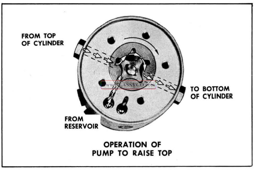
1957 Oldsmobile Raising the Top
B. Lowering the Top
When the green motor lead is energized, the motor drive shaft turns the rotors counter-clock wise as indicated by the large arrow in Fig. 17-118. The action of the pump rotors forces the fluid under pressure to the top of each cylinder. This action causes the fluid below the piston in each cylinder to be forced into the pump which recirculates the fluid to the top of each cylinder. The surplus hydraulic fluid due to piston rod displacement flows into the reservoir as shown.

1957 Oldsmobile Lowering the Top
MECHANICAL CHECKING PROCEDURES
If there is a failure in the Hydro-Lectric system and the cause is not evident, the mechanical operation of the top should first be checked. If the folding top assembly appears to have a binding action, disconnect the top lift cylinder piston rods from the top linkage and then manually raise and lower the top. The top should travel through its up and down cycle without any evidence of a binding action. If a binding action is noted when the top is being locked at the header, check the alignment of the door windows, ventilators and rear quarter windows with relation to the side roof rail weather strips. Make all necessary adjustments for correct top alignment. If a failure continues to exist after a check for mechanical failure has been completed, the Hydro-Lectric system should then be checked for electrical or hydraulic failures.
ELECTRICAL CHECKING PROCEDURES
If a failure in the Hydro-Lectric system continues to exist after the mechanical operation has been checked, the electrical system should then be checked. A failure in the electrical system may be caused by a low battery, breaks in the wiring, faulty connections, mechanical failure of an electrical component, or wires or components shorting to one another or to the body metal. Before beginning checking procedure check battery according to recommended procedure.
A. Checking For Current at the Folding Top Control Switch
- Disengage terminal block from rear of switch.
- Connect light tester to central terminal of switch terminal block.
- Ground light tester ground lead to the body metal.
- If light tester does not light, there is an open or short circuit between battery and switch.
B. Checking the Folding Top Control Switch
If there is current at the feed wire terminal of the terminal block the operation of the switch can be checked as follows:
- Place a #12 jumper wire on switch terminal block between center terminal (feed) and one of two motor wire terminals. If motor operates with jumper wire, but did not operate with switch, the switch is defective.
- Connect jumper wire between center terminal (feed) and other motor wire terminal on switch terminal block. If motor operates with jumper wire, but did not operate with switch, the switch is defective.
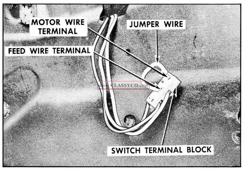
1957 Oldsmobile Checking Folding Top Control Switch
C. Checking Switch to Motor Lead Wires
If switch is found to be operating properly, the switch to motor lead wires can be checked as follows:
- Disconnect green switch-to-motor wire from motor lead in rear compartment.
- Connect a light tester to green switch-to-motor wire terminal.
- Ground light tester ground lead to body metal.
- Operate control switch downward. If tester does not light, there is an open or short circuit in wire.
- Disconnect red switch-to-motor wire from motor lead.
- Connect light tester to red switch-to-motor wire terminal.
- Operate control switch upward. If tester does not light, there is an open or short circ u it in wire.
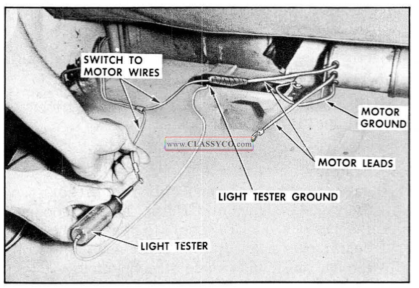
1957 Oldsmobile Checking Motor Lead Wires
D. Checking the Motor Unit
If a light test er indicates current at the motor lead terminals of the switch to motor wires but the motor unit does not operate from the switch, a final check of the motor unit can be made as follows:
- Check connection of motor ground wire to body metal.
- Connect a #12 gauge jumper from battery pos1t1ve pole to motor lead terminal that connects to green switch-to-motor wire. The motor should operate to lower top.
- Connect jumper wire to motor lead terminal that connects to red switch-to-motor wire. The motor should operate to raise top.
- If motor fails to operate on either or both of these checks, it should be repaired or replaced.
- If motor operates with jumper wire but will not operate from switch-to-motor wires, the trouble may be caused by reduced current resulting from damaged wiring or poor connections.
HYDRAULIC CHECKING PROCEDURE
Failures in the hydraulic system can be caused by lack of hydraulic fluid, leaks in hydraulic system, obstructions or kinks in hydraulic hoses, or faulty operation of a cylinder or pump. A pressure gauge can be used to check the pressure of the pump. See “Checking the Pressure of the Pump”.
A. Checking Hydraulic Fluid Level in Reservoir
- Operate top to raised position.
- At the rear compartment, remove pump and motor shield.
- Place absorbent rags below reservoir at filler plug.
- With a straight-bladed screw driver, remove filler plug. Fluid level should be at the lower edge of filler plug hole.
- If fluid is low, add Delco #11 hydraulic fluid (G.M. Hydraulic Brake Fluid Super #11) to bring to specified level.
- Install filler plug and pump and motor shield.
B. Checking Operation of Lift Cylinders
- Remove rear seat cushion and folding top compartment side panel assembly.
- Operate folding top control switch and observe the lift cylinders during “up” and “down” cycles for these conditions:
a. If movement of cylinder rods is not coordinated, or sluggish when the motor is actuated, check hydraulic hoses from motor and pump to cylinder for kinks.
b. If one cylinder rod moves slower than the other, cylinder having slower moving rod is defective and should be replaced. - If both cylinder rods move slowly or do not move at all, check the pressure of the pump. See “Checking the Pressure of the Pump’’.
C. Checking Pressure of the Pump
- Remove motor and pump assembly from rear compartment.
- Install plug in one port, and pressure gauge in port to be checked, as indicated in Fig. 17-121.
- Actuate motor with an applied terminal voltage within range of 9.5 volts to 11.0 volts. Pressure gauge should show a pressure be tween 240 p.s.i. and 280 p.s.i.
- Check pressure in other port.
NOTE: A difference in pressure readings may exist between the pressure port for top of cylinders and pressure port for bottom of cylinders. This condition is acceptable if both readings are within the limit of 240 p.s.i. and 280 p.s.i.
- If the pressure is not within specified limits, unit is defective and should be repaired or replaced, as required.
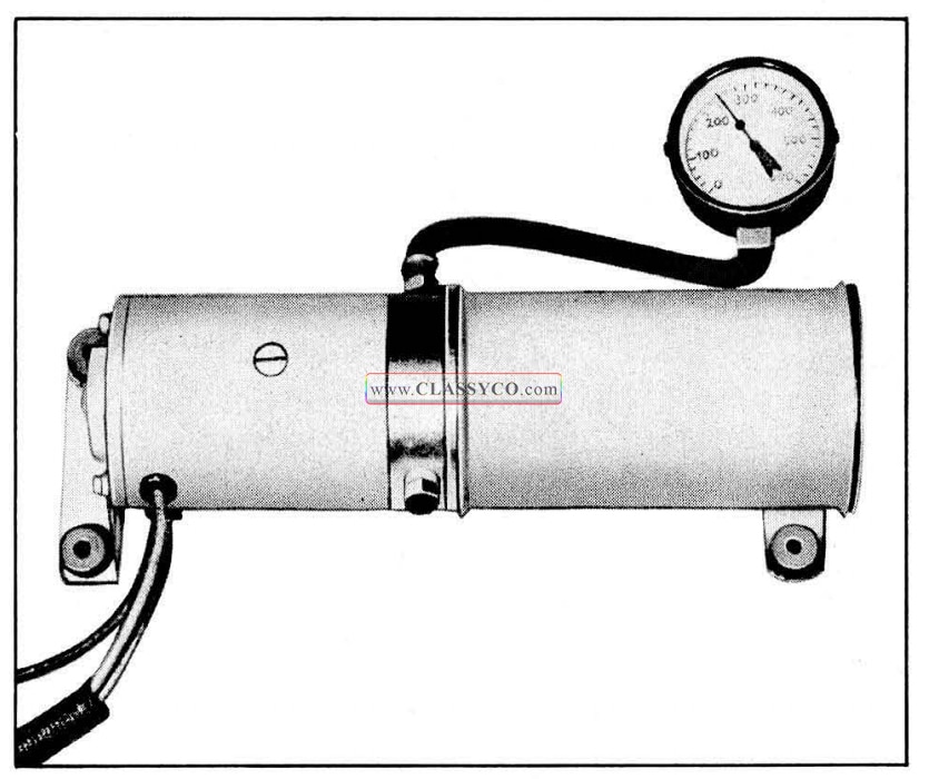
1957 Oldsmobile Checking Pump Pressure
WEATHERSTRIP AND ADJUSTMENTS
The following new features have been incorporated into the 1957 convertible styles:
- There are 2 locking handles used to secure the front roof rail to the windshield header.
- A newly designed folding top male hinge se cures the linkage to the body at the rear quarter area.
- “Floating” trim sticks, designed to pivot with the movement of the top as it is lowered or raised, are used to secure the top fabric at the rear quarter area. The rear end of the trim stick is attached to a support which, in turn, is secured to the rear quarter inner panel, while the forward end of the trim stick is positioned in a guide.
The removal and installation of the folding top trim assembly and weatherstrips are similar to the procedures used on past styles. Due to the new design of the folding top male hinge, the adjustment of the top linkage is new.
SIDE ROOF RAIL WEATHERSTRIPS
The sealing along each folding top side roof rail is accomplished by a front, center and rear section of weatherstrip. These weatherstrips are attached to the side roof rails with nuts on the integral studs of the weatherstrip section. In addition, the ends of the weatherstrip sections are secured to the side roof rail with screws.
The procedure below outlines the removal and installation of all 3 sections of weatherstrip. Each section may be removed and installed separately if desired.
Remove
- Lower top halfway.
- Remove weatherstrip attaching screw s at ends of each section of weatherstrip
- Remove screw securing end of front roof rail weatherstrip retainer. Then with a flat-bladed tool, carefully break cement bond between front roof rail rear weatherstrip and side roof rail front weatherstrip.
- Remove weatherstrip attaching nuts and washers and remove weatherstrips.
Install
- Clean off cement from front and side roof rails to insure clean cementing surf ace.
- Apply an approved weatherstrip cement to for ward portion of side roof rail front weather strip and to end of front roof rail rear weatherstrip to form “butt” joint with front roof rail weatherstrip.
- Apply a ribbon of body caulking compound along entire length of attaching surf ace on each side roof rail weatherstrip section just outboard of the integral studs and reverse removal procedure. (See Fig. 17-122) Clean off excess cement and sealer.
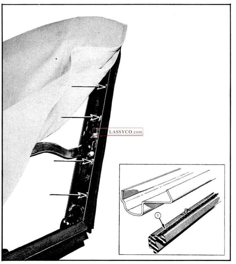
1957 Oldsmobile Side Roof Rail Weatherstrip (3)
Adjustments
- The side roof rail weatherstrip sections may be adjusted inboard or outboard. To adjust, remove attaching screws, loosen attaching nuts, and position as desired. Tighten nuts and reinstall attaching screws. If necessary, drill new hole for weatherstrip front attaching screw.
- The side roof rail weatherstrips may also be adjusted downward. To perform this adjustment, loosen weatherstrip as required and insert waterproof card board shim between weatherstrip and side roof rail, tighten weatherstrip attaching nuts and reinstall attaching screw s.
FRONT ROOF RAIL WEATHERSTRIPS
Two weatherstrips of different types are used along the front roof rail. The front weatherstrip is a trim cover ed 1/ 2″ diameter round rubber which is tacked to the front roof rail trim stick. The rear weatherstrip is a door weatherstrip-type section and is secured to the front roof rail by weatherstrip cement and by the r ear edge of a 2 piece metal retainer.
To remove either weatherstrip, lower the folding top and remove the 2 piece metal retainer; then remove tacks securing front weatherstrip or break cement bond securing rear weatherstrip. To install weatherstrip, reverse removal procedure. When installing rear weatherstrip, follow cementing instructions outlined for the door weatherstrip.
FOLDING TOP ADJUSTMENTS
The folding top linkage consists of three sections of right and l eft side roof rails and a front roof rail connected together by bolts, hinges, and a series of connecting links and bows. The top linkage is attached to the body at the rear quarter area by a male hinge bolted to an adjustable support. The front roof rail is locked at the windshield header by two cam locks which a e an integral pan of the two locking handles.
The following information outlines and illustrates procedures which ma y be used to correct misaligned folding top linkage. To correct some top variations, only a single adjustment is required; other top variations require a combination of adjustments. ln conjunction with adjustment of the folding top, it may be necessary to adjust the door, door glass, rear quarter glass, or the side roof rail weather strips. After any adjustments are made, the folding top should be checked at the rear quarter area f or proper fit. ln some cases, the folding top rear quarter trim stick front outer guide and the trim stick and support assembly may be adjusted slightly to obtain proper fit of top material at the rear quarter area.
ADJUSTMENT OF TOP AT FRONT ROOF RAIL CORNER BRACE
If the top, when in a raised position, is too far forward or does not move forward enough to allow the guide studs on the front roof rail to enter the holes in the striker assemblies, proceed as follows:
- Unlatch top and raise it above windshield header. Remove side roof rail weatherstrip front attaching screw.
- Loosen corner brace attaching bolts indicated in Fig. 17-123 and adjust front roof rail fore or aft as required. Repeat on opposite side if necessary.
NOTE: This adjustment is limited. If additional adjustment is required, it can be made at the folding top male hinge.
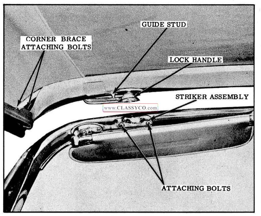
1957 Oldsmobile Front Roof Rail Locking Mechanism
ADJUSTMENT OF TOP AT LOCK HANDLE STRIKER AND FRONT ROOF RAIL GUIDES
If a difficult locking action, caused by misalignment of the front roof rail lock handle strikers, is encountered at the front roof rail, or if a closer fit of the front roof rail to the windshield head er is desired, proceed as follows:
- Unlatch top and raise it above windshield head er.
- Loosen striker attaching screws and adjust striker up or down or from side to side as required. If necessary, also loosen front roof rail guide attaching screws and adjust guide as required.
- If an additional upward adjustment of the front roof rail is desired, remove handle and install emergency washer into lock spindle cavity in handle, then install handle with emergency attaching screw.
ADJUSTMENTS OF TOP AT CONTROL LINK ADJUSTING PLATE
A. If there is a sag in the joint between the front and center side roof rail, proceed as follows:
- Remove folding top compartment side trim panel and loosen front bolt securing control link adjusting plate indicated in Fig. 17-124.
- Skip over serrations on support and pivot front portion of plate downward as required; then tighten bolt.
B. If the top linkage does not stack properly, proceed as follows:
- Loosen rear bolt securing control link adjusting plate; then pivot rear portion of adjusting plate over serrations as required to obtain desired stack height; then tighten bolt.
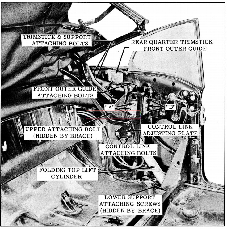
1957 Oldsmobile Convertible Top Adjustments
ADJUSTMENT OF TOP AT MALE HINGE SUPPORT
The male hinge is entirely new in design and method of attachment, thereby requiring new service procedures. The male hinge is secured to the support by 3 bolts at the front of the support and by 3 bolts at the side of the support. Prior to making an adjustment to raise the top linkage at the male hinge, loosen the 2 bolts securing the folding top rear quarter trim stick front outer guide to the rear quarter panel. This will prevent any possible damage to the top when it is raised after adjustment. After making an adjustment at the male hinge, check the folding top at the rear quarter area for proper fit and where necessary adjust the guide and the trim stick and support assembly.
A. If there is an excessive opening between the side roof rail rear weatherstrip and the rear quarter window, or if the front roof rail is too far forward or rearward, proceed as follows:
- Loosen 3 male hinge attaching bolts “A”. (See Fig. 17 -124)
- Move hinge fore or aft, as required, then tighten bolts.
- Lock front roof rail to windshield header, and check side roof rail alignment and stack position of top, and readjust if necessary.
- Lock front roof rail to windshield header and check fit of top material at rear quarter trim stick area and, if necessary, adjust trim stick. See “Adjustments of Rear Quarter Trim Stick and Support Assembly”. If adjustment is not necessary, tighten outer guide attaching screws.
B. If the side roof rail is too high or too low at the rear quarter window area, proceed as follows:
- Loosen bolts securing rear quarter trim stick front outer guide.
- Loosen attaching bolts “B”. In addition to bolts, support is secured firmly in place by serrations on contacting surfaces of support and brace.
- Adjust support up or down as required, then tighten bolts.
- Lock front roof rail to windshield header, and check side roof rail alignment. Read just if necessary.
- Check fit of top material at rear quarter trim stick area and, if necessary, adjust trim stick front guide. See “Adjustment of Rear Quarter Trim Stick and Support Assembly”.
ADJUSTMENTS OF REAR QUARTER TRIM STICK AND SUPPORT ASSEMBLY
In some cases, the rear quarter trim stick and support assembly may be adjusted slightly to remove wrinkles of the top material at the rear quarter area. To adjust the trim stick and support proceed as follows:
- Remove screws securing folding top compartment bag to seat back panel.
- Loosen support attaching bolts and outer guide attaching screws and adjust trim stick as required to obtain proper fit of top material; then tighten support attaching bolts.
- Lock front roof rail to windshield header; then position trim stick outer guide to contact top of inner guide and tighten outer guide attaching screws. (See Fig. 17-98)
- Install compartment bag attaching screws.
ELECTRIC WINDOW AND SEAT ADJUSTER CIRCUITS
The electrical circuit for 1957 styles is very similar to the circuit used in 1956 styles. The current for all of the electrical circuits is provided by a 12 volt battery. The power windows and electric horizontal seat adjuster are actuated by individual 12 volt, reversible direction, series wound motors. The 4-way power seat and the 6- way tilt type seat adjusters are powered by individual 12 volt reversible direction, shunt wound motors. Each of the electric motors is protected by a circuit breaker designed into the motor case. Other components of the electrical circuit are protected by a circuit breaker installed at the shroud panel.
In addition, the window circuit includes a relay assembly which prevents the operation of the window regulators and seat adjusters unless the ignition switch is turned on. On styles not equipped with power windows, a relay assembly is not included in the electrical seat circuit.
A new feature of the electric motors in the 1957 styles is the use of a newly designed socket and blade type connector which is attached directly to the motor case. The new connector provides a more positive electrical connection and facilitates the connecting of the wire harness leads to the motor leads.
1957 Oldsmobile Socket and Blade Type Connectors Electric Seat Motor
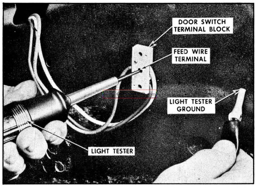
1957 Oldsmobile Checking Switch Feed Terminal
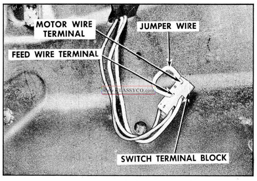
1957 Oldsmobile Checking Door Window Switch
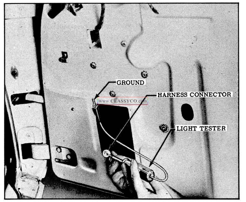
1957 Oldsmobile Checking for Current at Harness Connector
CHECKING WINDOW AND HORIZONTAL SEAT CIRCUIT
Failures in a circuit are usually caused by short circuits or open circuits. Open circuits are usually caused by breaks in the wiring, faulty connections, or mechanical failure in a component such as a switch or circuit breaker. Short circuits are usually caused by wires from different components of the circuit contacting one another or by a wire or component grounding to the metal of the body. See Fig. 17-133 for the circuit diagram of the power window and seat circuit.
A. Checking for Current at Door Window Switch.
- Connect light tester to center terminal of switch terminal block.
- Ground light test er ground lead to body metal.
- If tester does not light, there is no current at terminal block.
B. Checking Door Window Switch
- Place #12 jumper wire on switch terminal block between center terminal (feed) and one of two motor wire terminals. If motor operates with jumper wire, but did not operate with switch, switch is defective.
- Connect jumper wire between center terminal (feed) and other motor wire terminal on switch terminal block. If motor operates with jumper wire but did not operate with switch, switch is defective.
C. Checking the Wires Between Door Window Switch and Door Window Motor
- Place #12 gauge jumper wire on switch terminal block between center terminal (feed) and terminal of motor wire to be checked.
- Connect light tester to one of the terminals in harness socket as shown.
- Ground light tester ground lead to body metal.
- If tester does not light, there is no current at wire terminal contacting light tester.
D. Checking Door Window Motor
- Check ground of motor. Motor is grounded to door. inner panel through regulator frame attaching screws.
- Connect one end of a #12 gauge jumper wire to battery positive pole and other end to lowering cycle motor terminal. If motor fails to operate, motor unit is defective or mechanical stoppage exists in window system.
- Disconnect jumper wire from lowering cycle motor terminal and connect it to raising cycle motor terminal. If motor fails to operate, motor unit is defective or mechanical stoppage exists in the window system.
TYPICAL CONDITIONS
The following typical conditions and corrections have been listed as an aid for eliminating electrical failures in the electrically powered window regulator and horizontal seat adjusters. The right and left rear door or quarter window circuits are essentially the same as the right front door window circuit; therefore, all references to the right front door window circuit will also apply to the right or left rear door or quart er window circuits. It should be noted that multiple failures in the circuit may lead to a combination of conditions, each of which must be checked separately. See circuit diagram shown in Fig. 17-133.
A. Right door window will not operate from right door window switch but will operate from master switch. The trouble is located in the circuit between the feed wire terminal of the relay and the right door window motor lead terminals.
- Check feed wire from relay to right door window switch.
- Check operation of right door window switch.
- Check two motor wires from right door window switch to right door window motor leads.
B. Right door window will not operate from master switch, but will operate from right door window switch. The left door window will operate from master switch. The trouble is located in the circuit between the feed wire terminal of the master switch and the right door window motor lead terminals.
- Check operation of master switch.
- Check two motor wires from master switch to right door window motor lead terminals.
C. Right door window will not operate from master or right door window switches. The left door window operates from master switch. The trouble is located between the feed wire terminals of both switches and right door window motor.
- Check for mechanical stoppage in right door window.
- Check operation of master and right door window switches.
- Check motor wires from master and right door window switches to right door window motor leads.
- Check operation of right door window motor.
D. Right and left door windows will not operate from master switch, but right door window will operate from right door window switch. The trouble is located between the feed wire terminal on the relay and the master switch motor wire terminals.
- Check feed wire between relay and master switch.
- Check operation of master switch.
E. Left door window will not operate but right door window will operate from master and right door window switch.
The trouble is located between the feed wire terminal on the master switch and the left door window motor.
- Check for mechanical stoppage of left door window.
- Check operation of master switch.
- Check motor wires from master switch to left door window motor leads.
- Check operation of left door window motor.
F. Horizontal seat regulator will not operate, but door window operates.
The trouble is located between feed wire terminal of relay and the horizontal regulator motor.
- Check for mechanical stoppage of front seat assembly.
- Check feed wire between relay and seat adjuster switch.
- Check operation of seat adjuster switch.
- Check motor wires from seat adjuster switch to horizontal regulator motor leads.
- Check operation of horizontal regulator motor.
G. All electrically powered windows and horizontal seat regulators will not operate.
- Check battery.
- Check wire from ignition switch to relay.
- Check circuit from battery to circuit breaker.
- Check circuit breaker.
- Check wire from circuit breaker to relay.
- Check operation of relay.
- Check feed wire from relay to window and seat adjuster switches.
- Check operation of window and seat adjuster switches.
SIX-WAY SEAT CIRCUIT
TROUBLE SHOOTING PROCEDURES
The power-operated six-way tilt-type seat adjusters are operated by an actuator assembly which consists of a 12 volt reversible type motor with a built-in circuit breaker, a relay, gear box with jack screw and 3 spinning nut assemblies which include solenoids as shown in the illustrations. The motor assembly is controlled by a 3 button switch located on the left front seat side panel.
The seat circuit power feed wire is controlled by a relay assembly when the car is equipped with power windows. On these styles the ignition switch has to be turned to the “on” position to operate the seat adjusters.
The seat actuator includes a separate spinning nut assembly with a solenoid for each of the three basic movements of the seat: 1. Up and down front edge, 2. Up and down rear edge, 3. Fore and aft.
When the front button of the seat control switch is pushed up or down, current flows to the “up and down front edge solenoid”, actuating the solenoid and locking the spinning nut out of free wheeling. Simultaneously current flows to one of the motor field coils and to the relay assembly closing the contacts between the relay power source and the armature motor lead, thereby operating the seat adjuster motor. When either of the other 2 adjustments is desired and the switch is operated, the affected solenoid is actuated and the motor assembly operates in the same manner as outlined previously.
The power operated four-way seat adjusters and seat circuit is very similar to the power operated six-way tilt-type seat adjuster. The difference between the two types of adjusters is the number of spinning nut assemblies on the actuator jack screw and the connecting seat adjuster linkage. The four-way seat assembly is designed with 2 spinning nut assemblies; one spinning nut controls the horizontal adjustment of the seat, the other spinning nut controls the vertical movement of the seat; the six-way seat adjuster is designed with the 3 spinning nut assemblies as explained previously.
CHECKING PROCEDURES
It may be necessary to use only one or all of the procedures outlined to locate an electrical failure in the circuit, depending on the nature of the failure. If the location of the failure is evident, follow only the steps outlined to check the affected wire or component. If the location of the failure is not evident, follow the procedure as outlined. Before performing the checking procedures, check the seat adjusters and seat actuator assembly for mechanical failure. In addition, study the seat circuit diagrams located in this section to become familiar with the seat circuit.
NOTE: Fig. 17-129 shows the seat adjuster power unit with seat trim and springs removed.
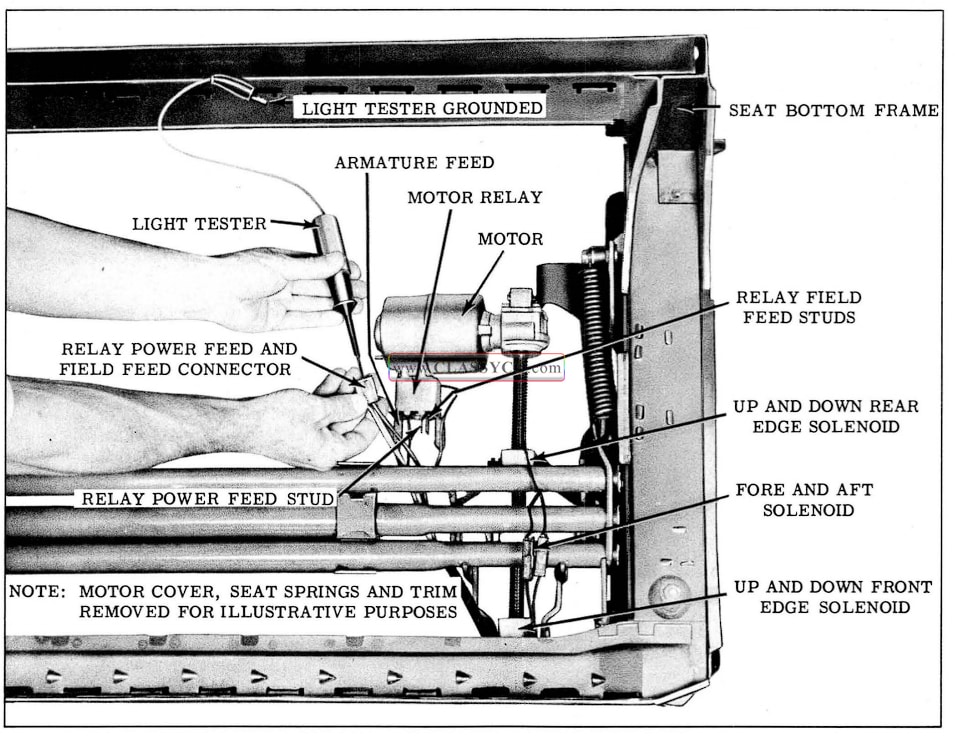
1957 Oldsmobile Testing Circuits of Six-Way Seat
A. Checking for Current at Circuit Breaker
- Connect one light tester lead to battery side of circuit breaker and ground other lead. If tester does not light, there is no current at battery side of circuit breaker.
- To check circuit breaker, disconnect switch feed wire from breaker, and with light tester check for current at switch side of circuit breaker. If tester does not light, there is no current flowing through circuit breaker.
B. Checking the Relay Assembly at the Shroud
- With light tester, check for current at circuit breaker side of relay. If tester does not light, there is an open or short circuit between circuit breaker and relay assembly.
- Turn ignition switch on and with light tester, check for current at seat control switch side of relay. If tester does not light, the relay is defective or there is a short or open circuit between ignition switch and relay assembly.
C. Checking for Current at the Seat Control Switch
- Connect one light tester lead to feed terminal switch block and ground other tester lead to body metal. See location #1 in Fig. 17-130 for the six-way seat, or in Fig. 17-131 for the four-way seat.
- If tester does not light, there is no current at switch block. Failure is caused by an open or short circuit between the switch block and power source.
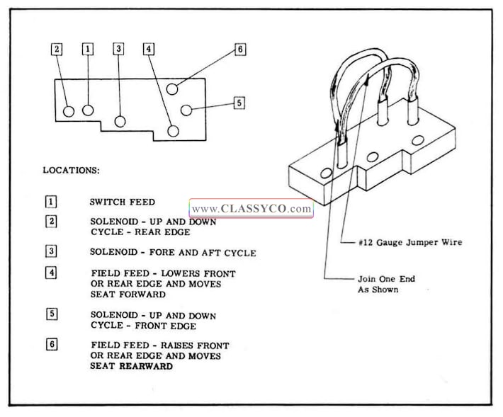
1957 Oldsmobile Six-Way Seat Switch Block
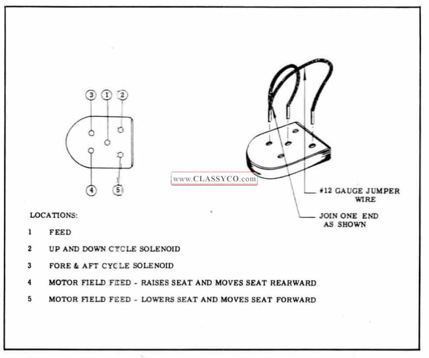
1957 Oldsmobile Four-Way Seat Switch Block
D. Checking for Current at Seat Adjuster Relay Feed
- Disengage feed connector from relay assembly.
- Insert one light tester lead into the re lay power feed connector slot and ground other light tester lead.
- If tester does not light, there is no current at end of feed wire. Failure is caused by an open or short circuit between the end of the wire and switch block.
NOTE: In the following operations, which specify the seat control switch to be actuated, a switch which has been checked for proper operation may be connected to the switch block. If a switch is not available, a three-way jumper wire can be made to perform the switch function. The procedure for making the jumper wire and the switch locations to be connected to obtain a specific movement of the seat are outlined in Figs. 17-130 and 17-131. If jumper is used, number the locations on the switch block as indicated in the illustrations.
E. Checking the Seat Control Switch
- Obtain switch or jumper wire and connect to switch block.
- Operate switch. If adjusters operate with new switch or jumper wire but did not operate with original switch, original switch is defective.
- Check all movements of seat adjuster.
F. Checking the Motor Field Feed Wires Between the Seat Control Switch and Motor Relay Assembly. (Fig. 17-132)
- Insert one light tester lead into field feed connector slot and ground other lead.
- Actuate seat switch to energize field wire being tested.
- If tester does not light, there is no current at end of wire. Failure is caused by an open or short circuit between end of wire and switch. Check other field wire in the same manner.
G. Checking the Relay Assembly (Fig. 17-132)
- Disconnect 3 motor leads from relay assembly.
- Connect one end of jumper wire to one of the field studs on the relay and ground the other end of the jumper wire.
- Connect one end of light tester to armature feed stud on relay and ground other light tester lead.
- Actuate seat control switch to energize the field stud which is not grounded. If tester does not light, the relay is defective.
H. Checking the Motor Assembly (Fig. 17-132)
- Disconnect armature feed and one of the motor field feeds from the relay assembly.
- Connect one end of a #12 gauge jumper wire to the battery positive pole and the other end to the armature feed and one of the field feeds.
- If motor does not operate, it is defective. Check the other motor field feed in the same manner. If motor does not operate it is defective.
NOTE: Certain component parts of the motor are available for service re placement as in the past.
I. Check the Wire Between the Solenoid and Switch (Fig. 17-132)
- Disconnect end of harness wire from connector of solenoid to be tested.
- Connect one-light tester lead to end of harness wire and ground other lead.
- Operate switch to energize wire being tested. If tester does not light, there is no current at end of harness wire. Failure is caused by an open or short circuit between end of wire and switch.
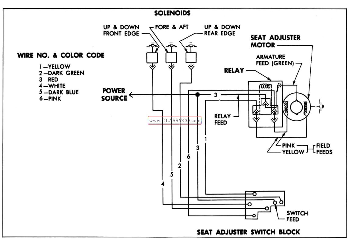
1957 Oldsmobile Six-Way Seat Circuit
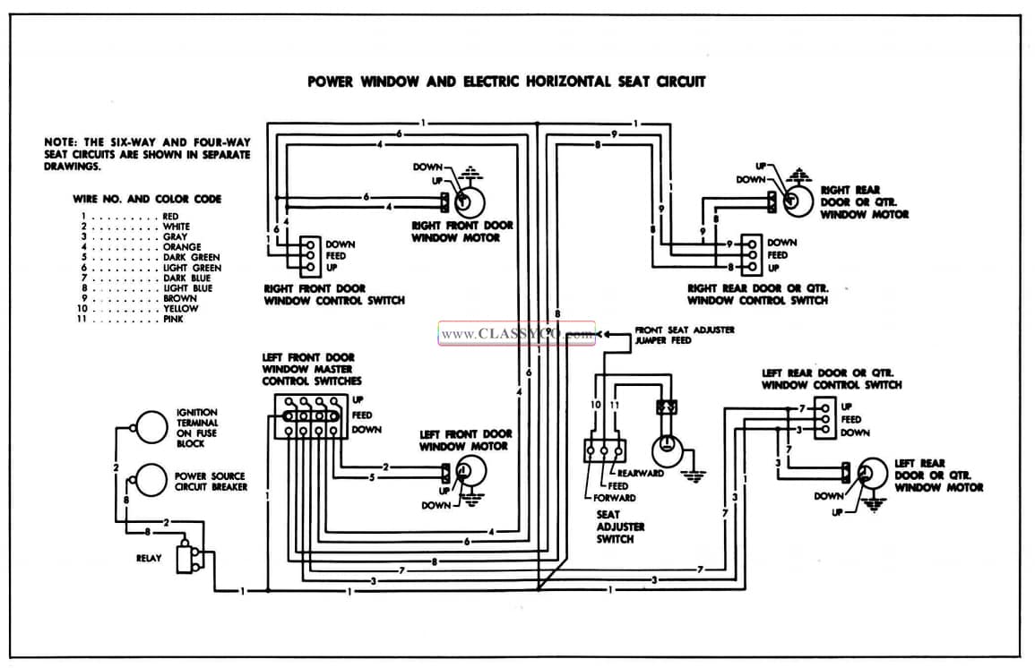
1957 Oldsmobile Power Window and Electric Horizontal Seat Circuit
J. Check the Solenoid
- Check installation of solenoid ground wire.
- Connect one end of a #12 gauge jumper wire to the battery positive pole and the other end to the solenoid lead being checked.
IMPORTANT: To prevent damaging the solenoid, do not energize solenoid with jumper wire for more than 1 minute.
- Operate switch to actuate adjuster motor and solenoid being checked.
- If adjusters do not function (spinning nut remains in free-wheeling), the solenoid is defective.
THREE-WAY JUMPER WIRE See Fig. 17-130 and 17-131
To make jumper wire, obtain 2 pieces of #12 gauge wire, each 4 1/2″ long. Join one end of each wire as shown in the drawing. The joined end can be inserted in the feed location in the switch block; one of the remaining ends can be inserted into one of the field locations in the switch block; the other end can be inserted into one of the solenoid locations.
IMPORTANT: To obtain a seat movement using a three-way jumper wire at the switch block, the switch feed location, one of the motor field wire locations, and one of the solenoid locations have to be connected simultaneously.
The switch locations to be connected to obtain a specific seat movement are outlined as follows:
(6-Way Seat)
A. To raise front edge of seat, place jumper in locations 1, 6 and 5.
B. To lower front edge of seat, place jumper in locations 1, 4 and 5.
C. To raise rear edge of seat, place jumper in locations 1, 6 and 2.
D. To lower rear edge of seat, place jumper in locations 1, 4 and 2.
E. To move seat forward, place jumper in locations 1, 4 and 3.
F. To move seat rearward, place jumper in locations 1, 6 and 3.
(4-Way Seat)
A. To raise seat, place jumper in locations 1, 2, and 4.
B. To lower seat, place jumper in locations 1, 2 and 5.
C. To move seat rearward, place jumper in locations 1, 3 and 4.
D. To move seat forward, place jumper in locations 1, 3 and 5.
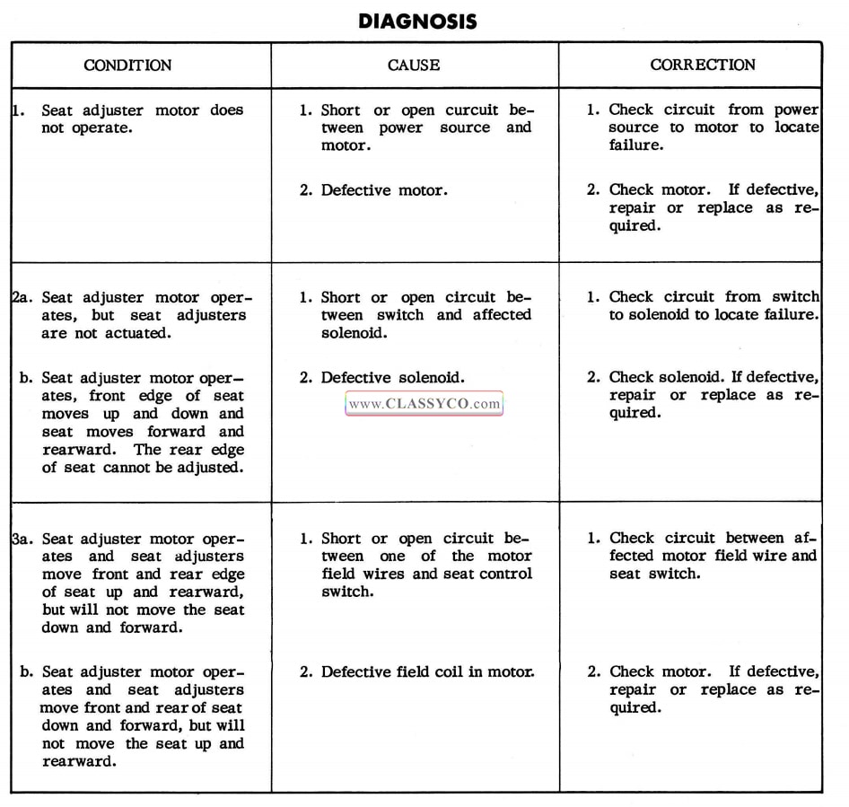
1957 Oldsmobile Body Diagnosis
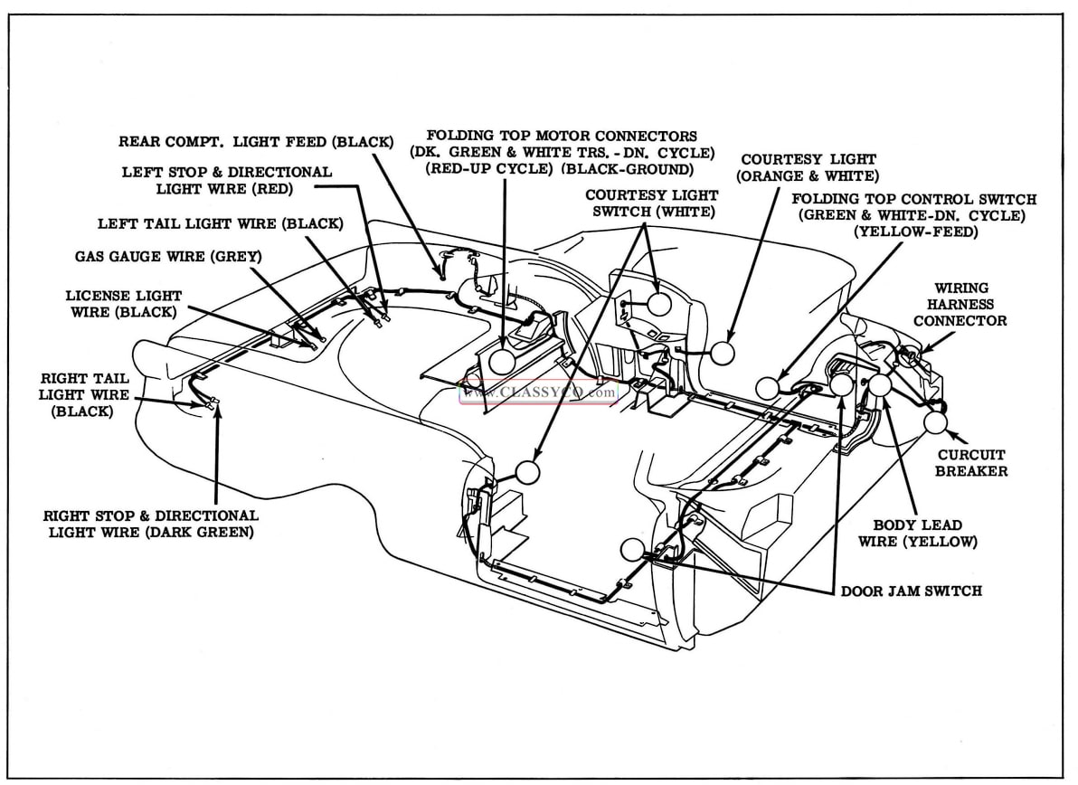
1957 Oldsmobile Body Wiring Installation-98 Convertible Shown
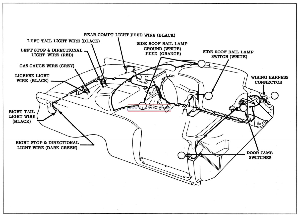
1957 Oldsmobile Body Wiring Installation-98 Holiday Coupe Shown
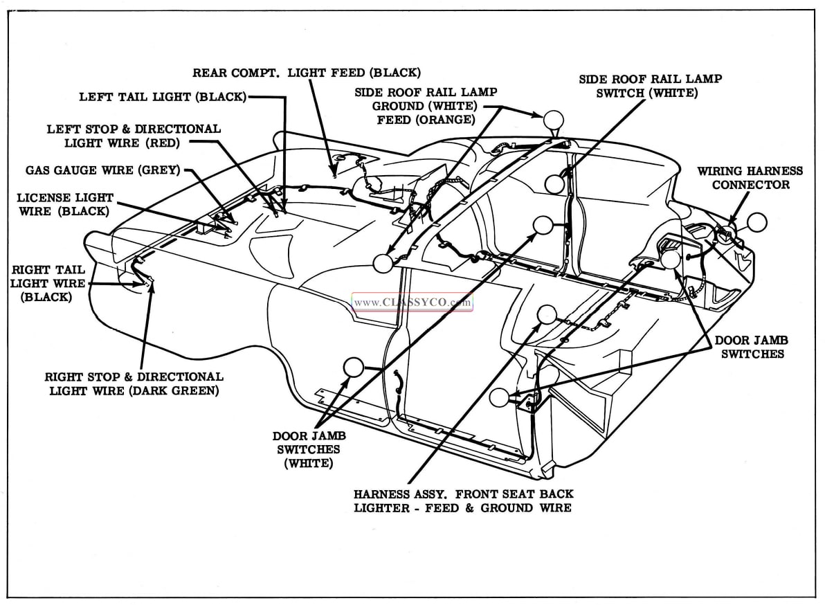
1957 Oldsmobile Body Wiring Installation-98 4 Door Sedan Shown
BODY LUBRICATION
The movable mechanical hardware parts of a Fisher Body are lubricated at the factory to insure proper and quiet operation. Because of the frequent use of some parts such as door locks and door lock strikers, it is important that these readily accessible parts be lubricated at least twice a year. Other body parts should be lubricated whenever access to the parts is available.
BODY PARTS WHICH SHOULD BE LUBRICATED AT LEAST TWICE A YEAR OR AS NECESSARY
FRONT DOOR HINGE HOLD-OPEN CLIPS
Wipe off dirt and apply a light coat of Lubriplate or its equivalent to hold-open clips indicated at “1” in Fig. 17-137.
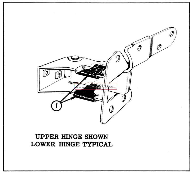
1957 Oldsmobile Front Door Hinge Hold-Open Clips
DOOR LOCKS
Wipe off dirt and apply a thin coat of stick type lubricant on surface of lock bolt housing indicated at “1” in Fig. 17 -138.
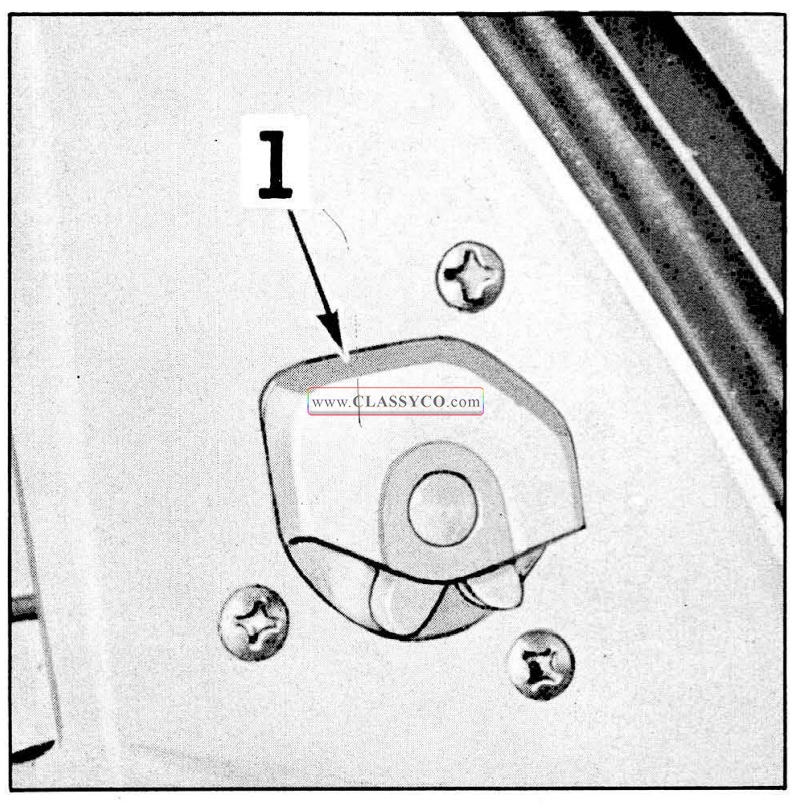
1957 Oldsmobile Door Lock Lubrication
DOOR LOCK STRIKER
Wipe off dirt and apply a thin coat of stick type lubricant to top surface of lock bolt striker teeth indicated at “1” in Fig. 17-139. After lubrication, close door several times and remove excess lubricant along the side edge of teeth.
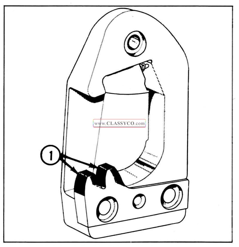
1957 Oldsmobile Door Lock Striker Lubrication
REAR DOOR HINGE AND HOLD-OPEN ASSEMBLY
Wipe off dirt and apply a light coat of Lubriplate to areas indicated by arrows at “1” in Fig. 17-140. Wipe off excess lubricant.
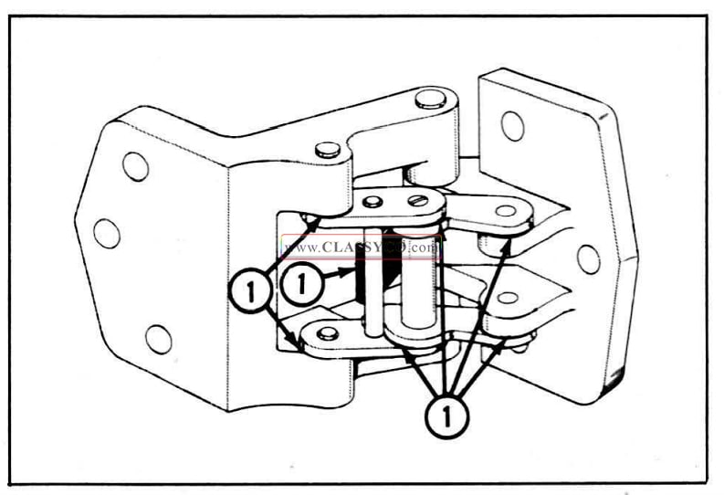
1957 Oldsmobile Rear Door Hinge and Hold-Open Assembly
REAR COMPARTMENT LID LOCK BOLT
Apply Lubriplate or its equivalent along area indicated at “1” in Fig. 17-141. Wipe off excess lubricant.
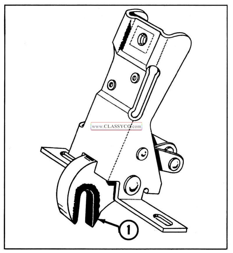
1957 Oldsmobile Rear Compartment Lid Lock Bolt Lubrication
FRONT SEAT SIDE PANELS – (Styles equipped with royalite or leather seat side panels and leather seat trim)
Apply a light coat of stick type lubricant along upper edge of front seat side panel indicated at “1” in section “8-B” in Fig. 17-142. Wipe off excess lubricant. The panel should be lubricated twice a year, or whenever an objectionable noise due to friction between the side panel and seat trim is present.
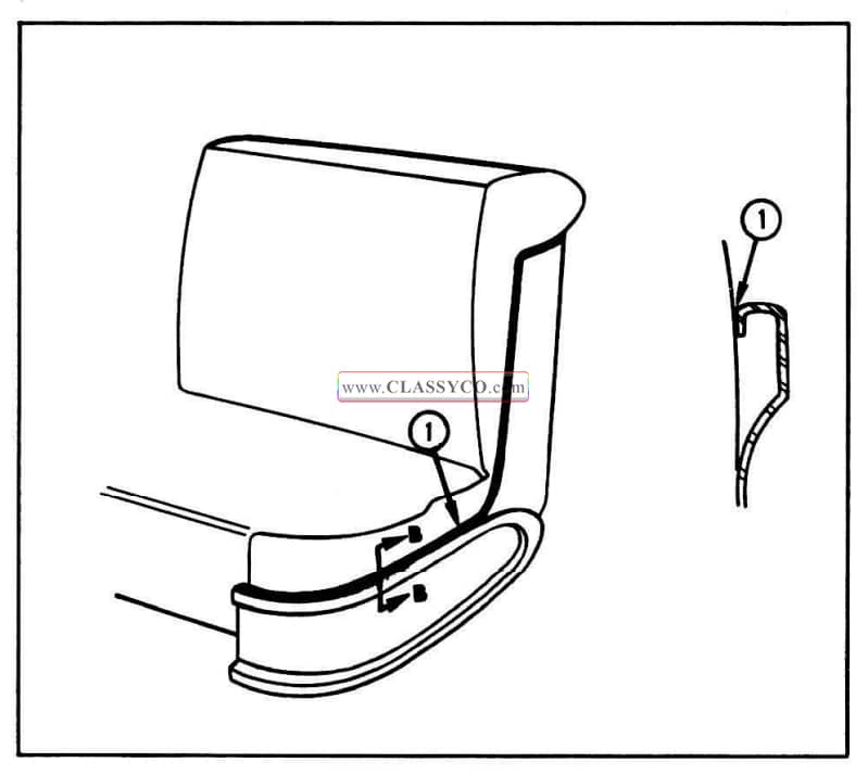
1957 Oldsmobile Front Seat Side Panel Lubrication
FOLDING TOP LINKAGE-(Convertible)
Apply a sparing amount of light machine oil to bearing points indicated by arrows in Fig. 17-143. Wipe off excess lubricant to prevent soiling trim.
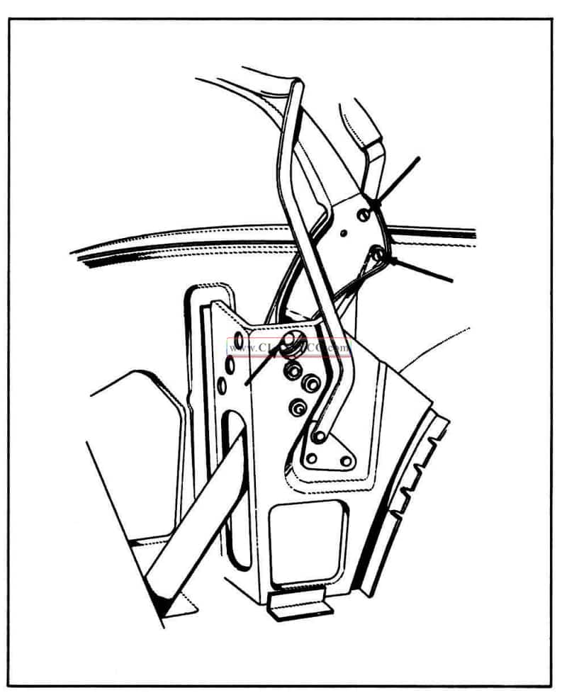
1957 Oldsmobile Folding Top Linkage
SIDE ROOF RAIL WEATHERSTRIP (4 Door Holiday Sedans)
Apply silicone rubber lubricant to surface of side roof rail weatherstrip indicated in Fig. 17-144. The weatherstrip section to be lubricated extends from approximately 2″ forward of the front door glass frame edge location and rearward for approximately 12″ as shown in Fig. 17-144.
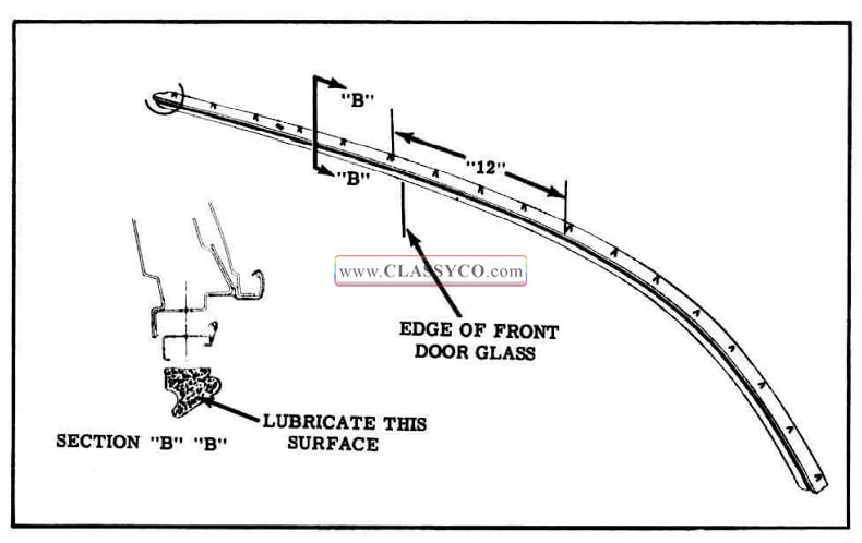
1957 Oldsmobile Side Roof Rail Weatherstrip Lubrication
SIDE ROOF RAIL MECHANICAL SEALING STRIP GASKET-(Holiday Coupes}
Apply light coat of silicone rubber lubricant to inner lip surface of gasket as indicated in Fig. 17-145. Lubricant is to be applied along entire length of gasket.
The gasket should be lubricated twice a year, or when the action of the movable outer sealing strip is retarded due to friction with the sealing lip of the gasket.
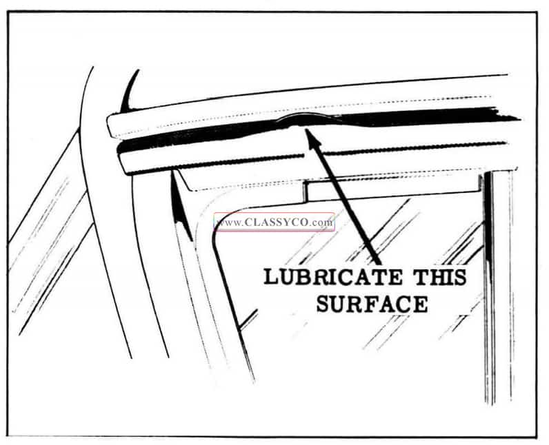
1957 Oldsmobile Lubrication of Side Roof Rail Mechanical Sealing Strip Gasket
DOOR BOTTOM DRAIN HOLE SEALING STRIP
Apply sparing amount of silicone rubber lubricant to surface of strip indicated at “1” in Fig. 17-146. This operation is performed to prevent lip of sealing strip from adhering to inner panel and plugging drain holes in bottom of door.
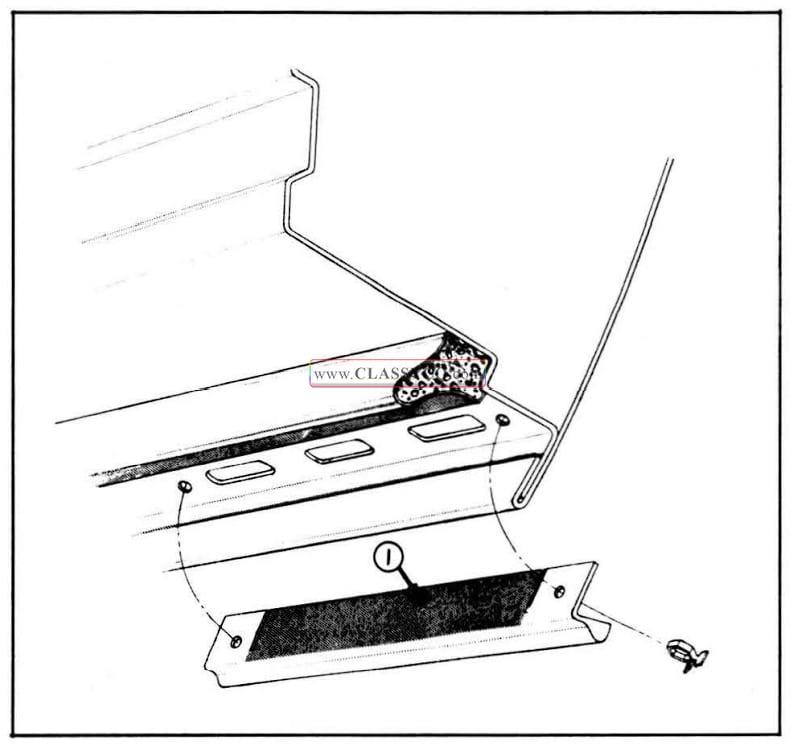
1957 Oldsmobile Lubrication of Door Bottom Drain Hole Sealing Strip
BODY PARTS WHICH SHOULD BE LUBRICATED WHEN ACCESS TO PARTS IS AVAILABLE
WINDSHIELD WIPER MOTOR AUXILIARY DRIVE AND WIPER TRANSMISSION PULLEYS
Apply Lubriplate or its equivalent to locations indicated at “1” in Fig. 17 -147.
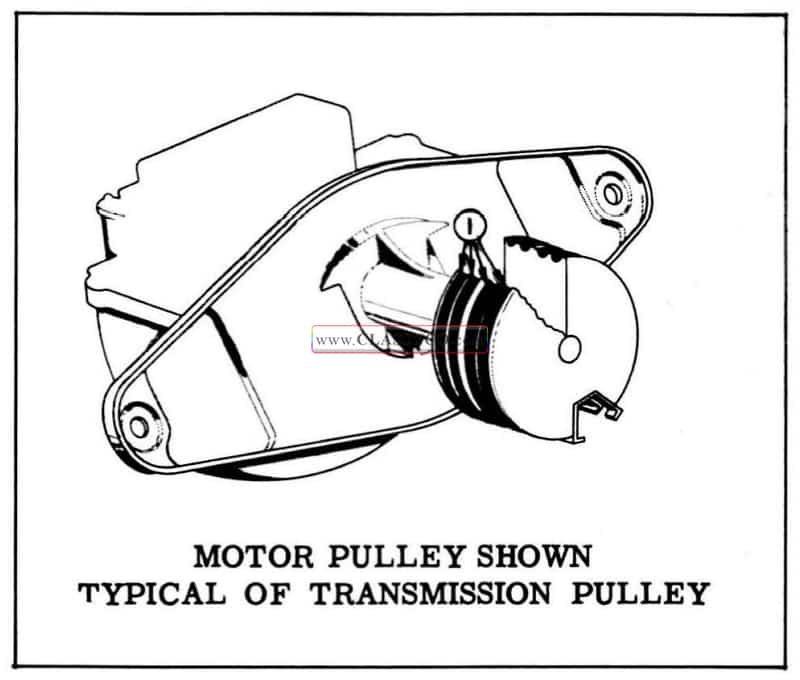
1957 Oldsmobile Lubrication of Windshield Wiper Auxiliary Drive Pulley
DOOR LOCK OUTSIDE HANDLE-(Holiday Coupes and Front Doors on 4 Door Holidays)
Apply light coat of Lubriplate or its equivalent to surface of lock cylinder shaft contacting the bell crank indicated at “1” in Fig. 17-148.
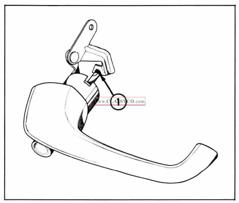
1957 Oldsmobile Lubrication of Door Lock Outside Handle
DOOR LOCK PARTS
Lubricate moving parts of door lock with Lubriplate or its equivalent.
FRONT AND REAR DOOR WINDOW REGULATOR SECTOR AND CHANNELS
Apply coat of Lubriplate or its equivalent to regulator sector indicated at “1”, and to sliding surface of window cam and guide channels indicated at “2 ” in Fig. 17-149.
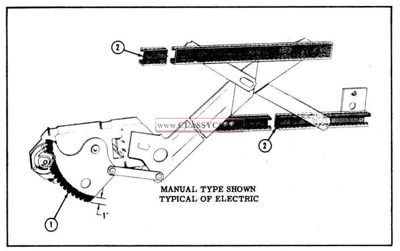
1957 Oldsmobile Lubrication of Front and Rear Door Window Regulator
SEAT REGULATOR JACK SCREW
Thoroughly wipe off old lubricant; then apply Lubriplate or its equivalent to jack screw. Operate seat adjuster to limit of all positions and wipe off excess lubricant.
EXTERIOR MOLDINGS
The exterior moldings are secured to the body by any one or a combination of attaching screws, bolt and clip assemblies, “snap-in” type clips, joint plates, and attaching studs.
Before removing a molding which must ‘be pried from a body panel or which must be slid along the paint finish, apply masking tape or some suitable protection to the body to prevent possible damage to the paint finish.
When installing moldings, apply medium-bodied sealer or body caulking compound to the body attaching holes.
NOTE: Figs. 17-150, 17-151, and 17-152, show the location and names of the moldings referred to in the following procedures for the 88 Series.
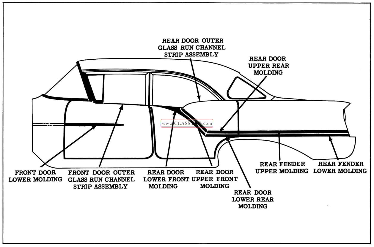
1957 Oldsmobile Body Exterior Moldings
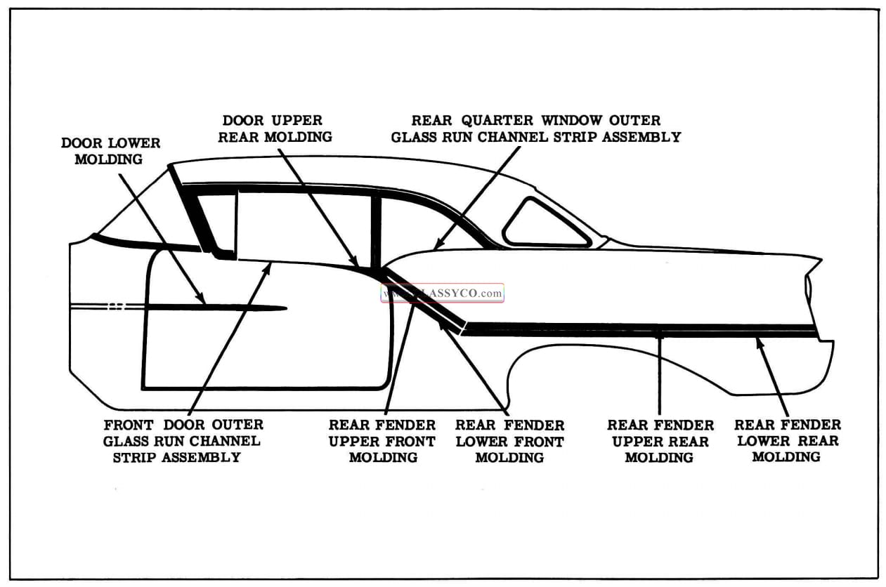
1957 Oldsmobile Body Exterior Moldings (2)
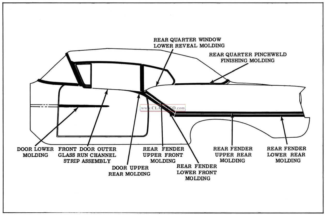
1957 Oldsmobile Body Exterior Moldings (3)
NOTE: Figs. 17-153, 17-154, and 17-155, show the location and names of the moldings referred to in the following procedures for the Super 88 and 98 Series.
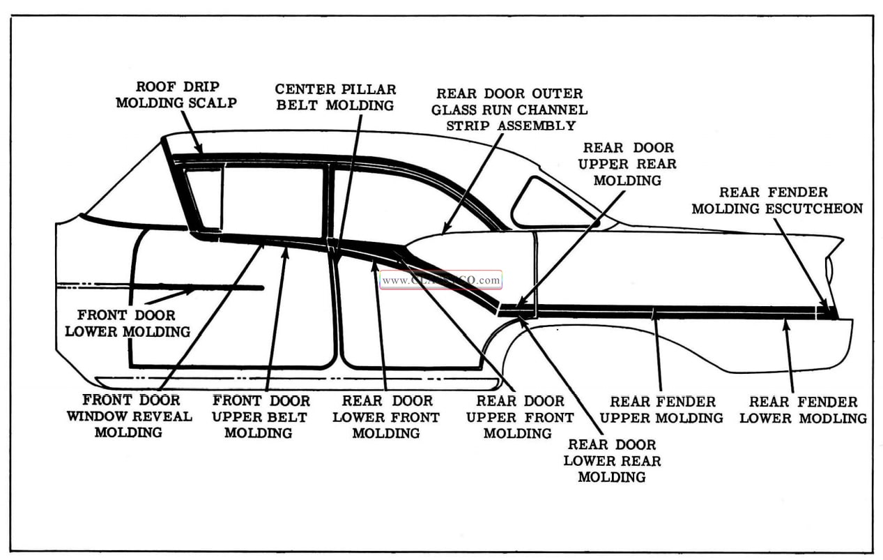
1957 Oldsmobile Body Exterior Moldings (4)
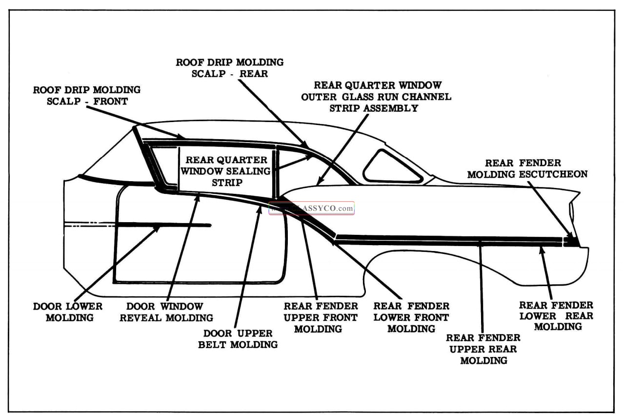
1957 Oldsmobile Body Exterior Moldings (5)
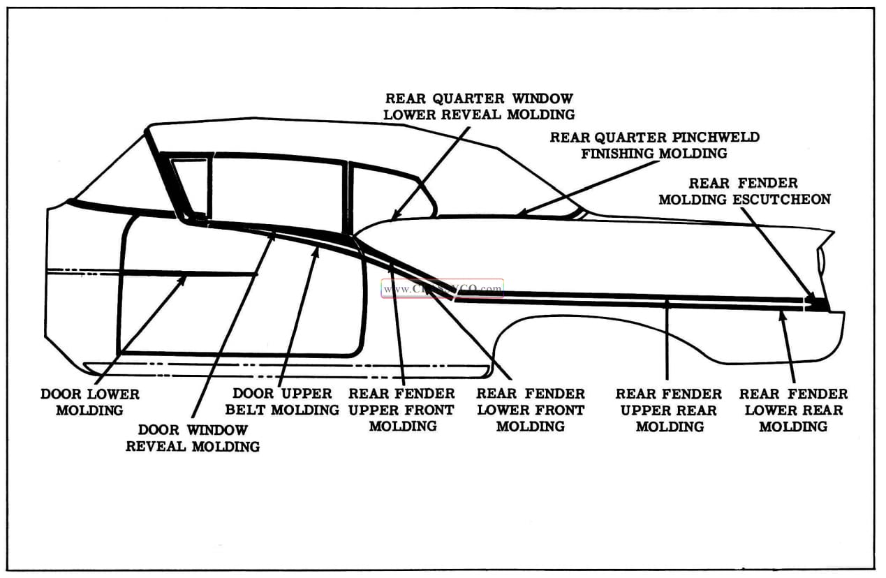
1957 Oldsmobile Body Exterior Moldings (6)
FRONT DOOR OUTER GLASS RUN CHANNEL STRIP ASSEMBLY-(AII 88 Series)
The assembly is secured to the door by means of attaching screws and integral “snap-in ” type clips.
Remove
- Remove the door trim assembly and the water deflector.
- Lower the window and disengage the window lower sash channel from the cam channel.
- Remove the attaching screws from each end of the strip assembly and, with a flat-bladed tool, disengage the assembly clips from the door.
- To install, reverse the removal procedure.
REAR DOOR OUTER GLASS RUN CHANNEL STRIP ASSEMBLY-(AII 4 Door Sedans and 4 Door Holidays)
The strip assembly is secured to the door by means of attaching screws.
Remove
- Remove the door window.
- Remove the attaching screws from the strip assembly and remove the assembly.
- To install the assembly, reverse the removal procedure.
REAR QUARTER WINDOW OUTER GLASS RUN CHANNEL STRIP ASSEMBLY-
(88 and S88 Two Door Sedans)
The strip assembly is secured to the body by “snap-in” type clips and an attaching screw at each end.
Remove
- Remove the rear quarter window.
- Remove the attaching screw at each end of the strip.
- With a flat-bladed tool, carefully disengage the strip assembly clips from the body and remove the assembly.
- To install the strip assembly, reverse the removal procedure.
REAR QUARTER WINDOW OUTER GLASS RUN CHANNEL STRIP ASSEMBLY
(All Holiday Coupes)
The strip assembly is composed of a long front and a short rear section. Both moldings are removed and installed as an integral unit because of the telescopic design. The strip assembly is secured to the body by means of “snap-in” type clips and by an attaching screw at each end of the assembly.
Remove
- Remove the rear quarter window.
- Remove the attaching screw at each end of the assembly.
- With a flat-bladed tool, carefully disengage the strip assembly front section clip from the body and remove the assembly.
Install
- Position and engage the strip assembly front section clips.
- Install the front attaching screws.
- Slide the strip assembly rear section to its rearmost position and install the attaching screw.
- Install all previously removed parts.
DOOR UPPER REAR MOLDING- (88 Two Door Sedan, 88 Holiday Coupe and S88 Convertible)
The molding is secured to the door by means of attaching screws and one attaching clip.
Remove
- Remove the door glass run channel strip assembly.
- Remove the attaching screw from the rear end of the molding at the hemming flange.
- Raise and rotate the top of the molding outboard from the door to disengage the molding clip from the door outer panel attaching hole and remove the molding.
Install
- Position the clip on the lower flange of the molding.
- Reverse the removal procedure.
REAR FENDER UPPER FRONT MOLDING (88 Two Door Sedan, 88 Holiday Coupe and S88 Convertible)
The molding is secured to the rear quarter outer panel by means of a joint plate, bolt and clip assemblies, and a stud and clip assembly.
Remove
- Remove the rear quarter trim assembly.
- Remove inner panel access hole cover.
- Remove the attaching nuts and washers from the front molding and loosen the adjacent nuts of the rear molding.
- To install the molding, replace the stud retaining clip, if necessary, and reverse the removal procedure.
NOTE: To remove the molding on convertible and Holiday coupes, slide the molding forward to disengage the molding from the joint plate at the rear.
To remove the molding on two door sedans, use a flat-bladed tool to disengage the molding front attaching stud from a retaining clip. Then slide the molding forward to disengage the molding from the joint plate at the rear.
REAR FENDER LOWER FRONT MOLDING (88 Two Door Sedan, 88 Holiday Coupe and S88 Convertible)
The molding is secured to the rear quarter outer panel by means of bolt and clip assemblies and a joint plate.
Remove
- Remove the rear quarter trim assembly.
- Remove inner panel access hole cover.
- Remove the attaching nuts and washers from the front molding and loosen the adjacent nuts of the rear molding.
- Slide molding forward to disengage the molding from the joint plate.
- To install the molding, reverse the removal procedure.
REAR DOOR UPPER FRONT MOLDING (88 4 Door Holiday and 88 4 Door Sedan)
The molding is secured to the door by means of a joint plate and bolt and clip assemblies.
Remove
- Remove the rear door trim assembly.
- Remove water deflector.
- Remove the attaching nuts from the molding and loosen the joint plate attaching nut.
- Slide moldings forward to disengage the molding from the joint plate.
- To install the molding, reverse the removal procedure.
REAR DOOR LOWER FRONT MOLDING (88 4 Door Holiday and 88 4 Door Sedan)
The molding is secured to the door by means of attaching screws and bolt and clip assemblies.
Remove
- Remove the rear door glass run channel strip assembly.
- Remove the attaching nuts from the molding and from the joint plate attaching bolt.
- Raise and slide molding forward.
- To install the molding, reverse the removal procedure.
REAR DOOR LOWER REAR MOLDING AND REAR DOOR UPPER REAR MOLDING
(88, S88 4 Door Holidays and 88, S88 4 Door Sedans)
Each molding is secured to the door by means of a joint plate bolt and clip assembly and a hemming flange attaching screw.
Remove
- Remove the rear door trim assembly.
- Remove the water deflector.
- Loosen the joint plate attaching nut and remove the hemming flange attaching screw.
- Slide molding rearward to disengage the molding from the joint plate.
- To install the molding, reverse the removal procedure.
REAR FENDER MOLDING ESCUTCHEON (All Super 88 and 98 Styles)
The escutcheon is secured to the body by a bolt and clip assembly. The rear fender moldings over lap the escutcheon and are secured to the body by a bolt and clip assembly at this location.
Remove
- Remove the attaching nut and washer and loosen the rear fender molding rear attaching nuts.
Install
- Position the escutcheon, install the attaching washer and nut and tighten the rear fender attaching nuts.
REAR FENDER LOWER MOLDING AND REAR FENDER UPPER MOLDING
(All 4 Door Holidays and 4 Door Sedans)
Each molding is secured to the body by means of bolt and clip assemblies at each end and by “snap in” type clips. The Super 88 and 98 Series make use of an escutcheon at the ends of the lower moldings.
To remove a rear fender molding on 88 Series:
- Remove the attaching nuts and washers from each end of the molding and using a flat-bladed tool, carefully disengage the molding with retaining clips from the body.
To remove rear fender molding on Super 88 or 98 Series:
- Remove the molding attaching nuts and carefully disengage the molding retaining clips from the body.
NOTE: To install rear fender molding, reverse the removal procedure.
REAR FENDER UPPER REAR MOLDING AND REAR FENDER LOWER REAR MOLDING
(88, S88 Two Door Sedans, All Holiday Coupes and Convertibles)
Each molding is secured to the body by means of a joint plate, a bolt and clip assembly and “snap in” type clips.
Remove
- Remove the rear quarter trim assembly.
- Remove the inner panel access hole cover.
- Remove the rear attaching nut and washer.
- Loosen the joint plate attaching nut at the front of the molding.
- Using a flat-bladed tool, carefully disengage the molding retaining clips from the body.
- Slide molding rearward to disengage the molding from the joint plate.
- To install the molding, reverse the removal procedure.
FRONT DOOR UPPER BELT MOLDING (All Super 88 and 98 Series)
The molding is secured to the door by means of a “slide-in” attachment at the front, by snap-in type clips and a hemming flange screw at the rear.
Remove
- Remove the molding attaching screw at the hemming flange.
- Use a flat-bladed tool to disengage the molding retaining clips from the door outer panel.
- Slide the lower molding rearward to disengage the molding from the reveal molding and remove the molding.
- To install the molding, replace the retaining clips where required and reverse the removal procedure.
FRONT DOOR WINDOW REVEAL MOLDING (All Super 88 and 98 Series)
The glass run channel strip assembly is an integral part of the molding. The molding is secured to the door by means of “slide-in” retaining clips along the lower area and attaching screws at the ends and upper area of the molding. In order to remove the front door window reveal molding, it is first necessary to remove the front door upper belt molding, and, on two door styles, the door outside handle.
Remove
- Remove the door trim assembly.
- Remove the water deflector.
- Lower the window and disengage the window lower sash channel from the cam channel.
- Remove the front door upper belt molding and, on two door styles, the front door outside handle.
- Remove the reveal molding attaching screws along the strip assembly at the front end of the molding and at the rear hemming flange.
- Remove the attaching screw and clip from the door outer panel at the lower front of the molding.
- Roll the upper section of the molding away from the door to disengage the molding clips from the door outer panel and remove the molding.
- To install the molding, position the molding clips on the molding and reverse the removal procedure.
REAR DOOR UPPER FRONT MOLDING (S88, 98 4 Door Holidays and S88, 98 4 Door Sedans)
The molding is secured to the door by the glass run channel strip assembly attaching screws, bolt and clip assemblies, and a joint plate.
Remove
- Remove the glass run channel strip assembly.
- Remove the attaching nuts and washers from the molding.
- On Super 88 series, remove the joint plate attaching nut and washer. On 98 series, remove the joint plate attaching screw access hole plug and remove the attaching screw.
- Raise and slide the molding forward to disengage the molding from the joint plate.
- To install the molding, reverse the removal procedure.
REAR DOOR UPPER REAR MOLDING AND REAR DOOR LOWER REAR MOLDING (98 4 Door Holiday and 98 4 Door Sedan)
Each molding is secured to the door by means of a joint plate and a hemming flange attaching screw.
Remove
- Remove the joint plate attaching screw.
- Remove the hemming flange attaching screw and slide the molding to the rear.
- To install the molding, reverse the removal procedure.
REAR DOOR LOWER FRONT MOLDING (98 4 Door Holiday and 98 4 Door Sedan)
The molding is secured to the door by means of a hemming flange attaching screw, a ”T” nut joint plate, and “snap-in” type clips.
Remove
- Remove the joint plate attaching screw.
- Remove the hemming flange attaching screw.
- With a flat-bladed tool, disengage the molding clips from the door outer panel.
- Slide molding forward to disengage the molding from the joint plate.
- To install the molding, replace the retaining clips where required and reverse the removal procedure.
REAR DOOR LOWER FRONT MOLDING (S88 4 Door Holiday and S88 4 Door Sedan)
The molding is secured to the door by means of a hemming flange attaching screw, a bolt and clip assembly joint plate, and “snap-in” type clips.
Remove
- Remove the door trim assembly.
- Remove the water deflector.
- Loosen the joint plate attaching nut.
- Remove the hemming flange attaching screw.
- With a flat-bladed tool, disengage the molding clips from the door outer panel.
- Slide molding forward to disengage the molding from the joint plate.
- To install the molding, replace the retaining clips where required and reverse the removal procedure.
REAR DOOR UPPER REAR MOLDING AND REAR DOOR LOWER REAR MOLDING (S88 4 Door Holiday and S88 4 Door Sedan)
Each molding is secured to the door by means of a bolt and clip assembly joint plate and a hemming flange attaching screw.
Remove
- Remove the door trim assembly.
- Remove inner panel access hole cover.
- Loosen the joint plate attaching nut.
- Remove the hemming flange attaching screw and slide the molding to the rear.
- To install the molding, reverse the removal procedure.
CENTER PILLAR BELT MOLDING (S88, 98 4 Door Holidays and S88, 98 4 Door Sedans)
The molding is secured to the center pillar filler strip by two screws.
Remove
- To remove the molding, open the doors and remove the attaching screws.
- To install the molding, position it properly and install the attaching screws.
REAR QUARTER WINDOW LOWER REVEAL MOLDING-(AII Convertibles)
The molding is secured to the return flange of the rear quarter outer panel by attaching screws. The rear attaching screws secure both the reveal molding and the rear quarter pinchweld finishing molding to the body.
Remove
- Remove the rear quarter window and the molding attaching screws.
- Raise the front end of the molding and slide forward to disengage it from the pinchweld finishing molding.
- To install the molding, reverse the removal procedure.
REAR QUARTER PINCHWELD FINISHING MOLDING, RIGHT AND LEFT-(AII Convertibles)
The rear quarter pinchweld finishing moldings are secured to the body by snap-on type clips and by attaching screws. The integral center escutcheon of the right molding overlaps the left molding. It is necessary to loosen the right molding before the left molding can be removed.
Remove
- Remove the rear quarter window to gain access to the molding front attaching screw and re move the screw.
- Detach the front end of the folding top compartment bag from the rear seat back panel.
- Remove the center trim stick attaching screws to gain access to the molding rear attaching screws.
- Remove the molding attaching screws.
- With a cushioned block and hammer carefully disengage the molding from the pinchweld flange and remove the molding.
- To install the molding, apply waterproof body tape over the pinchweld flange, and reverse the removal procedure.
ROOF DRIP MOLDING SCALP (S88, 98 4 Door Holidays)
The roof drip molding scalp is secured to the body by attaching screws. The side roof rail weatherstrip retainer and reveal molding overlap the scalp molding.
Remove
- Remove the side roof rail weatherstrip and retainer.
- Remove the scalp attaching screws.
- To install the scalp, reverse the removal procedure.
ROOF DRIP MOLDING SCALP (S88, 98 4 Door Sedans)
The roof drip molding scalp is secured to the body by attaching screws.
Remove
- Open the doors.
- Remove the scalp attaching screws and remove the scalp.
- To install the scalp, reverse the removal procedure.
ROOF DRIP MOLDING SCALP-FRONT (All Holiday Coupes)
The front scalp is secured to the body by attaching screws, the side roof rail weatherstrip retainer or mechanical sealing strip, and the rear quarter window sealing strip.
Remove
- Remove the weatherstrip retainer or mechanical sealing strip.
- Remove rear quarter window sealing strip.
- Remove the scalp attaching screws and remove the scalp.
- To install the scalp, reverse the removal procedure.
NOTE: Seal the scalp by applying a bead of medium-bodied sealer to the inner radius of the scalp prior to installation.
ROOF DRIP MOLDING SCALP-REAR (All Holiday Coupes)
The rear scalp is secured to the body by means of an attaching screw and by a “snap-in” type clip. The front scalp overlaps the rear scalp.
Remove
- Remove the front scalp molding.
- Remove the attaching screw from the lower front attachment of the molding.
- Using a flat-bladed tool, carefully disengage the retaining clip at the rear of the scalp from the body and remove the scalp.
- To install the scalp, replace the retaining clip, if necessary, and reverse the removal procedure.
NOTE: Seal the scalp by applying a bead of medium-bodied sealer along the inner radius of the scalp prior to installation.
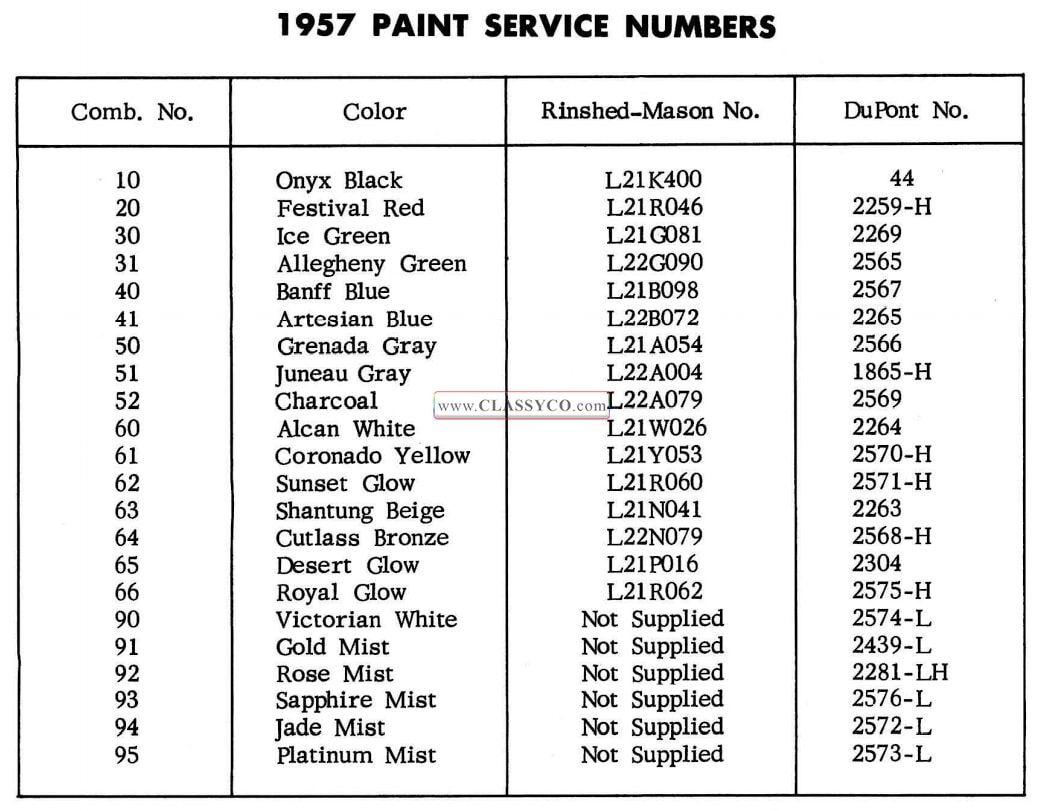
1957 Oldsmobile Paint Service Numbers
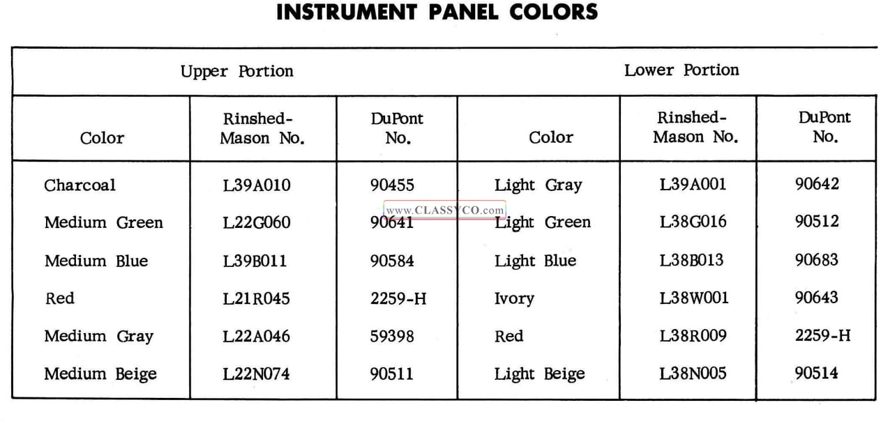
1957 Oldsmobile Instrument Panel Colors
FIESTA
The basic service requirements for the 1957 Fiesta are the same as its counterpart with the exception of the following parts; headliner, roof top chrome moldings, lift gate, tail gate, second seat, 1/4 panel, and flooring.
HEADLINER
Remove and Install
The headliner consists of five sections of perforated hardboard, retained by plastic retainer finishing moldings and aluminum side retainers. The plastic retainer finishing moldings snap on to retainers which are attached to the roof top crossbows. The side aluminum retainers are retained by screws to the side roof inner rail. To remove the front headliner section, the windshield upper garnish moldings, rear view mirror support and sun visors must be removed. To remove the rear section, the rear roof top header finish moldings must be removed.
- With a screw driver or suitable tool, pry one end of the plastic retainer finishing molding loose from its retainer. Then “peel” the plastic retainer finishing molding from its retainer. (See Fig. 17-156)
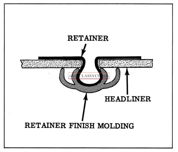
1957 Oldsmobile Headliner and Retainer
NOTE: Two retainer finishing moldings must be removed to remove any one panel, with the exception of the front and rear panels as mentioned above.
- Slide headliner section back sufficiently to clear finishing molding retainer, then lift sides out of side retainers and remove section.
- To install, reverse removal procedure.
NOTE: When reinstalling plastic retainer finishing moldings, slip one end of finishing molding into side retainer and snap finishing molding onto retainer.
ROOF TOP CHROME MOLDINGS (S88 DSW)
Remove and Install
The nine roof top chrome moldings are retained by “T” bolt type clip retainers which are self sealing. There are six “T” bolts retaining each molding.
- Remove the three rear sections of the headliner and side dome light escutcheons.
- Remove the nuts from the “T” bolts, then remove molding.
- To install, reverse removal procedure.
NOTE: When reinstalling moldings, use new dished washer and nut assemblies to in sure adequate sealer to seal the “T” bolt and opening.
LIFT GATE
The lift gate is of one piece construction with two dual pivot type hinges, two support rods and two torque rods for assist in opening or closing the lift gate.
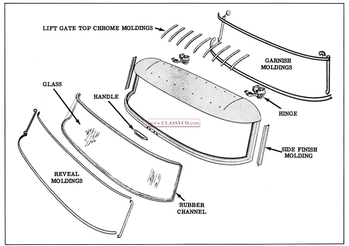
1957 Oldsmobile Lift Gate Assembly
TORQUE RODS
Remove and Install
With the lift gate in full open position proceed as follows:
- Remove the roof top rear header finish molding, secured by five screws.
- Remove the right and left rear header coiner finish moldings, each secured by three screws.
- Remove the rear headliner section.
- Loosen four bolts attaching each liftgate hinge to header.
- Remove torque rods retainer clip from center of header.
- With suitable tool, disengage torque rod ends from lift gate hinges.
CAUTION: Torque rods are under tension. Use extreme caution when disengaging from hinges. - Pry torque rod from under lift gate hinge and slide hooked end from retaining slot.
- To install, reverse removal procedure.
NOTE: Having loosened lift gate hinge, it will be necessary to adjust lift gate after reinstalling torque rods. Torque the lift gate hinge bolts 6 to 7 ft. lbs.
HINGES
Remove and Install
- Prop lift gate in full open position and lock both lift gate supports.
- Remove torque rods.
- Remove hinge attaching bolts.
- To install, reverse removal procedure.
NOTE: Align lift gate as outlined in ADJUSTMENTS procedure and torque hinge bolts 6 to 7 ft. lbs.
SUPPORTS
Remove and Install
- With lift gate in full open position and supports locked, either right or left support may be replaced by removing the four attaching bolts.
NOTE: Remove and replace only one support at a time.
- To install, reverse removal procedure.
GARNISH MOLDINGS
Remove and Install
- Remove right and left upper corner garnish moldings.
- Remove right and left side garnish moldings.
- Remove upper and lower garnish moldings.
- To install, reverse removal procedure.
WINDOW REVEAL MOLDINGS
The reveal moldings are retained by “T” bolt type clips.
Remove and Install
- Remove the garnish moldings.
- Remove nuts from reveal molding “T” bolts and remove moldings.
- To install, reverse removal procedure.
NOTE: To remove the upper or lower reveal moldings it is necessary to remove the right and left side reveal moldings due to the “overlap” of the side reveal moldings over the upper and lower reveal moldings.
SIDE FINISH MOLDING
The side finish molding (chrome S88) (painted 88) snaps on the side of the lift gate at the front edge and is retained by screws under the reveal moldings at the rear edge.
GLASS
Remove and Install
- Remove garnish moldings.
- Remove the reveal moldings.
- Lift glass and rubber channel from lift gate.
- To install, install rubber channel on glass. Apply medium body sealer around base of channel, then position lip of rubber channel over the flange. Apply weatherstrip cement between outside lip of rubber channel and glass, then reverse removal procedure.
LIFT GATE TOP CHROME MOLDINGS
Remove and Install
- Remove perforated hardboard headliner extension, secured by four screws.
- Remove nuts from molding “T” bolt retainer and remove molding. (See Fig. 17-158)
- To install, reverse removal procedure.
NOTE: When reinstalling moldings, use new dished washer and nut assemblies to insure adequate sealer to seal the ”T” bolt and opening.
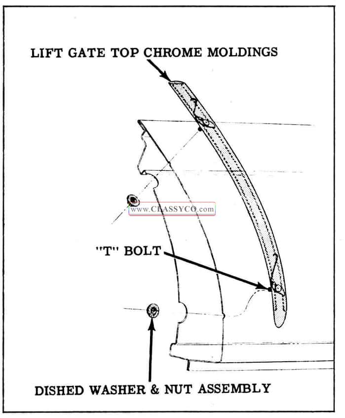
1957 Oldsmobile Molding Attachment
ADJUSTMENTS
Fore or Aft
- Remove roof top rear header finish molding.
- Loosen four hinge retaining bolts, which secure the hinge to the roof top rear header.
- Tap lightly with a rubber mallet or suitable tool, on the hinge plate to attain desired position.
- Tighten the hinge retaining bolts “finger tight”, then check lift gate alignment in opening.
NOTE: Proper seating of the weatherstrip is of primary importance.
- When desired alignment has been attained, torque the hinge retaining bolts 6 to 7 ft. lbs.
- Reinstall finish molding.
Up, Down or Sideways
- Loosen four hinge retaining bolts which secure the hinge to the lift gate.
- Using a rubber mallet or suitable tool, tap the sides, upper or lower ends of the lift gate to desired position.
- Tighten the hinge retaining bolts “finger tight” and check lift gate alignment in opening.
- When desired alignment is attained, torque the hinge bolts 6 to 7 ft. lbs.
NOTE: Upon completion of any lift gate adjustment, close tail gate and check for satisfactory engagement of the lift gate locks (See Fig. 17-159) to the lift gate locking plates. Check for proper weatherseal with paper.
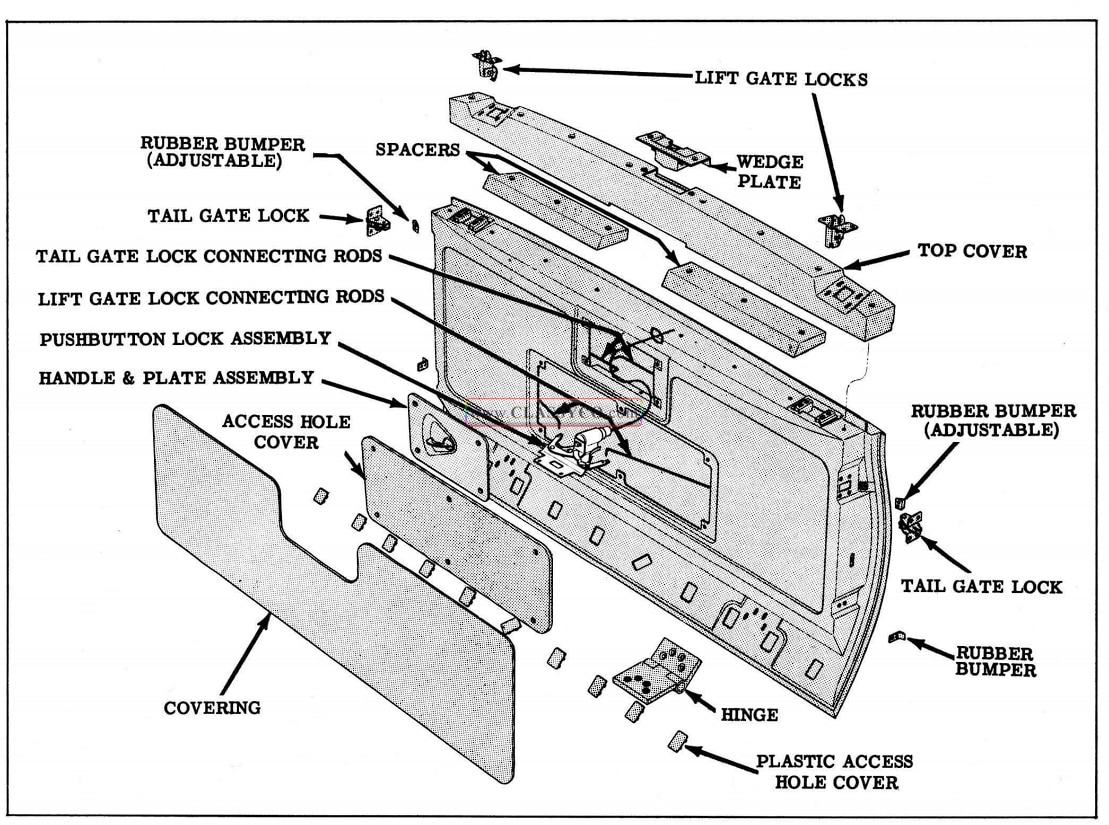
1957 Oldsmobile Tail Gate Assembly
TAIL GATE
The tail gate is of one piece construction with two standard hinges, two supports, a pushbutton lock cylinder which controls tail gate to lift gate locking, and an inside handle which controls the tail gate locks.
VINOLEUM COVER
The vinoleum is cemented to the tail gate with Armstrong Cork Co. #285 cement.
Remove and Install
- With a putty knife or suitable tool, pry the vinoleum from the tail gate panel.
- To install, clean panel thoroughly and install new vinoleum cover. Coat the back side of the covering as well as the panel with Armstrong Cork Co. #285 cement. Allow it to become tacky, then position the covering and press roll onto panel.
LOCK HANDLE AND PLATE ASSEMBLY
Remove and Install
- Remove the four screws which secure the lock handle and plate assembly to the tail gate.
- Lift the lock handle and plate assembly sufficiently to gain access to the lock connecting rods.
- Disengage the lock connecting rods from the handle by removing spring clips. Remove handle and plate assembly.
- To install, reverse removal procedure.
TAIL GATE LOCKS AND CONNECTING RODS
Remove and Install
- Remove lock handle and plate assembly.
- Remove four lock attaching screws on tail gate lock.
- Pull lock, with connecting rod attached, from tail gate.
- To install, reverse removal procedure.
NOTE: The tail gate locks are not interchange able; therefore, be certain the proper lock is on the correct side.
PUSH BUTTON LOCK ASSEMBLY
Remove and Install
- Remove tail gate lock handle assembly.
- Remove two screws on inner flange of lock handle opening in tail gate inner panel.
- Disengage lift gate lock connecting rods from push button lock assembly and remove assembly.
- To install, reverse removal procedure.
LIFT GATE LOCKS AND. CONNECTING RODS.
Remove and Install
- Remove tail gate lock handle assembly.
- Disconnect lift gate lock connecting rods from the push button lock assembly.
- Remove four attaching screws securing each lift gate lock.
- Pull locks and connecting rods from tail gate.
- To install, reverse removal procedure.
EMBLEM
Remove and Install
- Remove tail gate inner panel vinoleum cover.
- Remove access hole cover, attached with six screws.
- Remove emblem attaching clips and remove emblem from tail gate.
- To install, reverse removal procedure.
LETTERS
Remove and Install
- Remove plastic snap-on cover with a screw driver or suitable tool.
- Remove snap-on retaining clips and remove letter.
- To install, reverse removal and procedure.
SUPPORT HINGES
The tail gate support hinges are secured to the tail gate and body by two bolts each. The bolts are to be torqued 18 to 20 ft. lbs.
NOTE: Adjustment is obtained by loosening the support bolt on the tail gate and shifting bolt until outer end of the tail gate is 1″ above the level of the auxiliary floor.
ADJUSTMENTS
Fore, Aft and Side
- Raise spare tire floor section cover.
- Loosen four hinge attaching bolts for each hinge on rear body sill.
- Using a rubber mallet or suitable tool tap the sides or bottom of the tail gate to obtain the desired alignment.
- Tighten the bolts “finger tight” and check the tail gate alignment in body opening.
NOTE: When checking the tail gate alignment in body opening, be sure to check tail and lift gate locks for proper engagement. Any necessary adjustment of the tail or lift gate locks can be obtained by loosening the attaching screws on the locks and setting locks to required position for proper engagement.
- After desired alignment of tail gate has been attained, torque hinge attaching bolts and tail gate and lift gate lock attaching screws 6 to 7 ft. lbs.
Up and Down
- Loosen four hinge attaching bolts for each hinge on the tail gate.
- Using a rubber mallet or suitable tool, tap the lower or upper end of the tail gate for desired alignment.
- Tighten the bolts “finger tight” and check tail gate alignment in body opening.
NOTE: When checking alignment in body opening be sure locks are aligned for proper engagement. Maintain a minimum of 5/16″ clearance from the bottom of the tail gate to the lower body panel (with tail gate closed), to prevent damage to the lower panel when the tail gate is lowered. Adjust locks if necessary as outlined in notation for Fore, Aft, and Side Adjustments.
- After desired alignment is attained, torque bolts and lock screws 6 to 7 ft. lbs.
WEATHERSTRIPS
The weatherstrips for the tail and lift gates are secured to the sides and upper edges of the body opening, the top and bottom of the tail gate by 3-M Super Weatherstrip cement.
REAR QUARTER PANEL
GARNISH MOLDINGS
The 1/4 window garnish moldings are retained by screws. The upper and lower garnish moldings are over-lapped by the side garnish moldings and the upper rear corner finish molding. To remove either the upper or lower garnish molding it is necessary to remove both side garnish moldings and the rear corner finish moldings.
REVEAL MOLDINGS
The 1/4 window upper and lower reveal moldings are retained by means of “T” bolt type clips. The front (S88 Only) and rear side reveal moldings are retained with snap-on clips.
Remove and Install
- Remove garnish moldings.
- With screw driver or suitable tool pry up one end of the front (S88) or rear reveal molding.
- Work screw driver along molding, prying up to disengage from snap-on clips.
- Remove nuts from the “T” bolts retaining the upper and lower moldings and remove moldings.
- To install, reverse removal procedure.
GLASS
Remove and Install
- Remove garnish moldings.
- Remove four inside upper, lower and side glass retaining plates, attached with screws to window opening.
- Push glass from outside in, and remove with rubber channel.
- To install, position rubber channel on glass. Apply medium body sealer around base of channel, then install lip of rubber channel over window opening flange. Apply weatherstrip cement between outside of rubber channel and glass, then reverse removal procedure.
TRIM
Remove and Install
- Remove rear 1/4 corner trim plate secured to panel by four screws.
- Remove sides and lower 1/4 window garnish moldings.
- Remove two screws at front side of 1/4 panel trim and remove panel.
- To install, reverse removal procedure.
FLOORING
The auxiliary flooring is composed of individual pressed panels with vinoleum covering. These coverings are cemented to the panels with Armstrong Cork Co. #285 cement. Any panel covering can be removed with a putty knife or suitable tool, working the cemented cover loose from the panel. Once removed, the vinoleum covering cannot be reused. It must be replaced with a new covering.
SECOND SEAT
The second seat is a folding seat. The back of the seat back-rest and the underside of the seat cushion become a part of the auxiliary flooring when folded.
SEAT BACK-REST OR CUSHION
Remove and Install
- With seat partially unfolded remove attaching screws from the bottom side of the seat back rest. To remove the seat cushion, remove attaching screws from the front under side of the cushion.
- Slip the seat back-rest or cushion upward from the attaching screws, to disengage from the attaching clips underneath the cushion and remove cushion.
- To install, reverse removal procedure.
SEAT BACK-REST OR CUSHION BACKING
The seat back-rest or cushion backing, which becomes a part of the auxiliary flooring when the seat is unfolded, can be removed by removing the horse-shoe clip from the back side of the hinges and removing the pivot bolts.
SEAT ADJUSTMENTS
Fore and aft adjustments of the seat are obtained through the seat hinges, which are bolted to the floor pan, by loosening the hinge to floor pan attaching bolts, and through shimming of the seat back-rest locking catch located on the upper portion of the rear wheel housing.
BODY BOLTS
To minimize vibration and noise, the body bolts must be properly torqued. Body bolts which are not tightened sufficiently will cause body “chucking” and damage to the insulators. If body bolts are tightened excessively, the cushioning effect of the insulators is impaired resulting in squeaks and body “drumming”. Body bolts used with the plain rubber mount must be torqued 10 to 25ft. lbs., and body bolts used with metal sleeve type rubber mount must be torqued 25 to 40 ft. lbs. For various body mount locations and usage, refer to Figs. 17-160, 17-161, 17-162, and 17-163.
1957 Oldsmobile Body Mount Locations
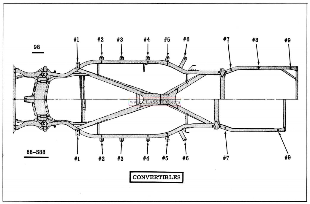
1957 Oldsmobile Body Mount Locations (2)
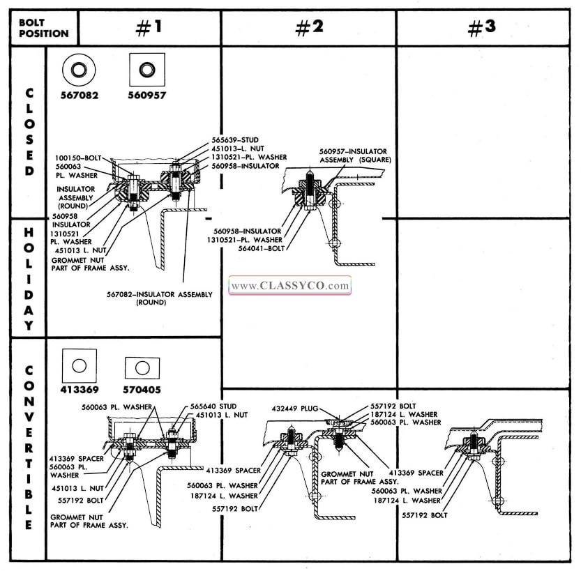
1957 Oldsmobile Body Mount Locations (3)
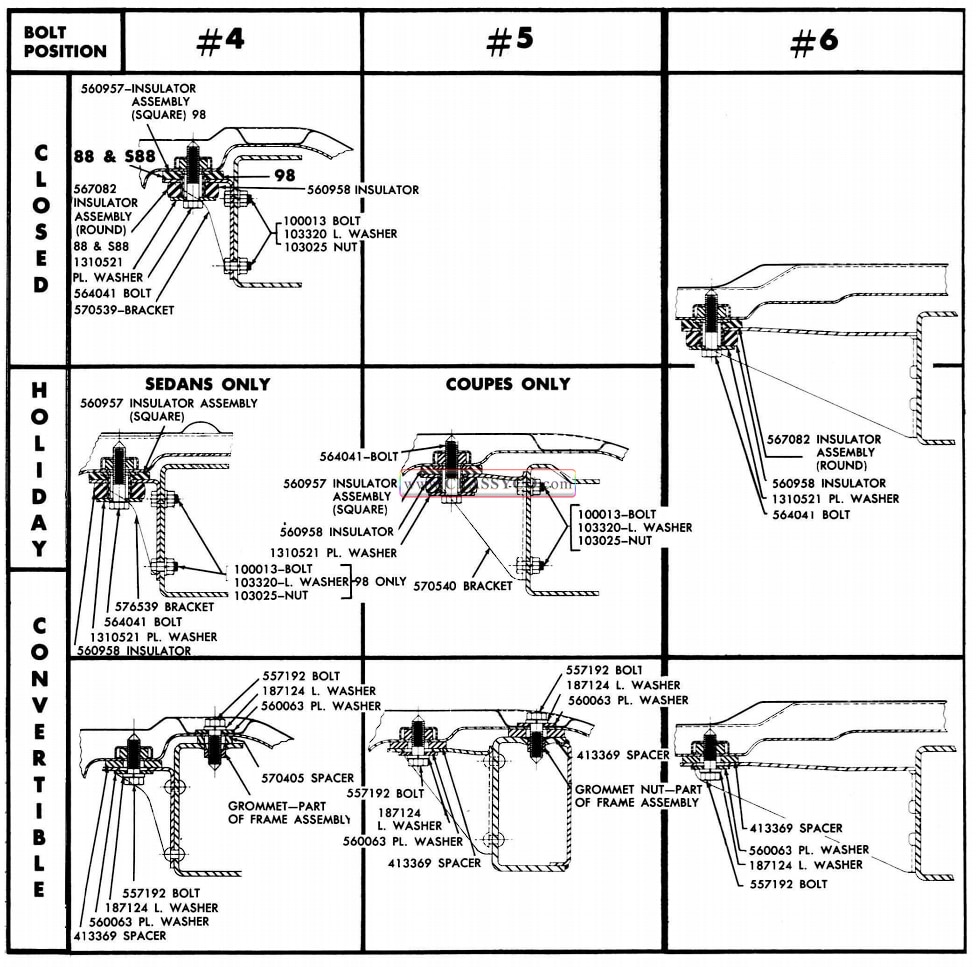
1957 Oldsmobile Body Mount Locations (4)
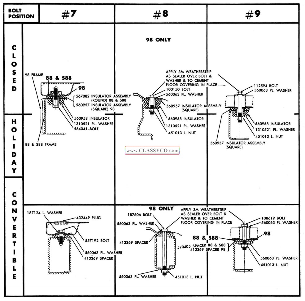
1957 Oldsmobile Body Mount Locations (5)
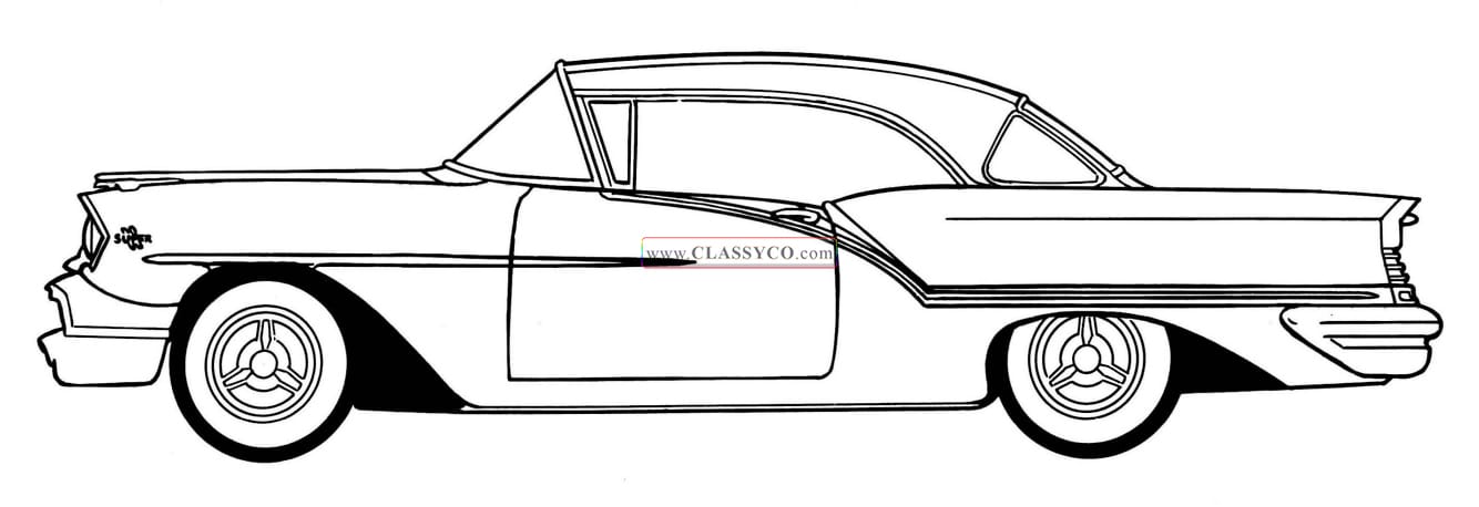
1957 Oldsmobile S88 Holiday Coupe (DHC)
1957 Oldsmobile 98 Holiday Coupe (DHC)