AIR CONDITIONING
GENERAL DESCRIPTION
The Oldsmobile Air Conditioning system provides refrigerated and dehumidified air to cool the car interior. All air is filtered to remove dust and other foreign materials. The system uses both outside air and recirculated air.
The temperature of the air entering the passenger compartment is regulated by a single control. Outside air is directed through the evaporator and discharged from the passenger compartment outlets for normal ventilation. For normal cooling, 100% outside air passes through the evaporator core. For maximum cooling, approximately 75% recirculated air and 25% outside air is directed through the evaporator core.
Air Outlets (Fig. 14-1)
Refrigerated air enters the passenger compartment through four air outlets on the instrument panel. Adjustable air outlets are located on either side of the instrument panel and in the finishing panel. The left and right hand air outlets may be adjusted to direct the air as desired. The finishing panel outlets each contain a door which can be controlled to change the direction of air flow or to shut off the air. For maximum cooling these doors should be wide open. Floor cooling is automatically provided by discharging air directly to the floor from fixed openings in the air manifold located under the instrument panel.
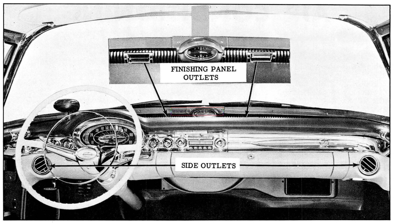
1957 Oldsmobile Air Outlets
The air conditioning control assembly is mounted in the instrument panel. A three speed fan switch is located in the control unit. (See Fig. 14-2)
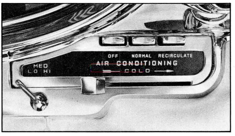
1957 Oldsmobile Controls
FAST COOL DOWN
To rapidly cool a car which has been standing for a period of time in the sun, open both finishing panel outlet doors. Depress “NORMAL” button and adjust temperature lever to full right. Open car windows just long enough to expel hot air. After the car has cooled, adjust temperature control lever position to suit individual comfort. Direct air flow by adjusting outlets at either end of instrument panel. The recommended position of these outlets, for best over-all front and rear seat cooling, is when the outlets are adjusted to direct the air flow along the inside roof line.
DRIVING CONDITIONS
For normal driving conditions, the driver may adjust the temperature of cool air by selecting a control lever position to suit individual comfort. Selection of blower speed is dependent upon the amount of air forced into the passenger compartment by the forward motion of the car. Thus, when driving in heavy traffic, it may be desirable to set the Fan Switch in “HI” position. At higher car speeds, air will be forced by the forward motion of the car into the passenger compartment in greater volume, thereby lessening the speed requirements of the blower motor. It then may be desirable to set the Fan Switch in “MED” or “LO” position.
SERIAL NUMBER
The serial number plate is attached to the top side of the compressor and includes the Serial Number and Model Number. The starting Serial No. is 45FC008. (See Fig. 14-3) The Model No. is 5911124. Service compressors (less hand shut off valves and solenoid clutch) have the same Model No. and the starting Serial No. is 13HC861.
IMPORTANT: Always include both Serial No. and Model No. on reports.

1957 Oldsmobile Compressor Serial Number Plate
OPERATION OF SYSTEM (Fig. 14-4 and 14-5)
CONTROLS
The air conditioning control assembly is mounted in the instrument panel to the right of the steering column. To obtain ventilation without refrigeration, leave the temperature control lever all the way to the left and press the “NORMAL” button. When the temperature control lever is moved to the right and the “NORMAL” or “RECIRCULAT ING” button is engaged, the compressor solenoid clutch engages and activates the compressor. Movement of the control lever from left to right increases the degree of cooling within the car. The fan switch is located below the control lever. Three speeds, “MED”, “LO”, and “HI”, are available for forced ventilation.
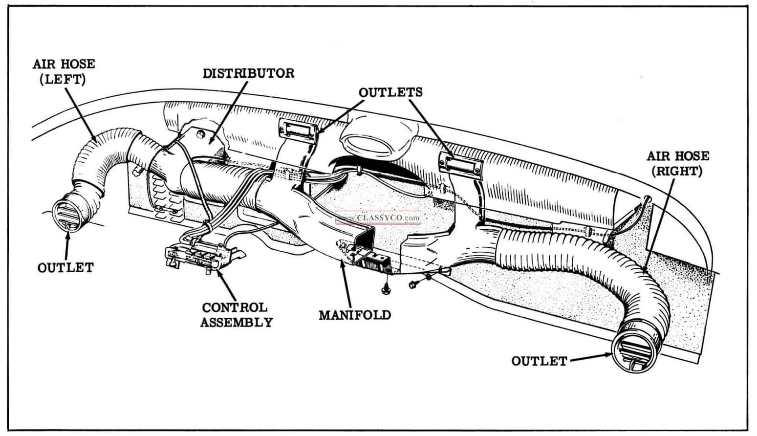
1957 Oldsmobile Unit Location
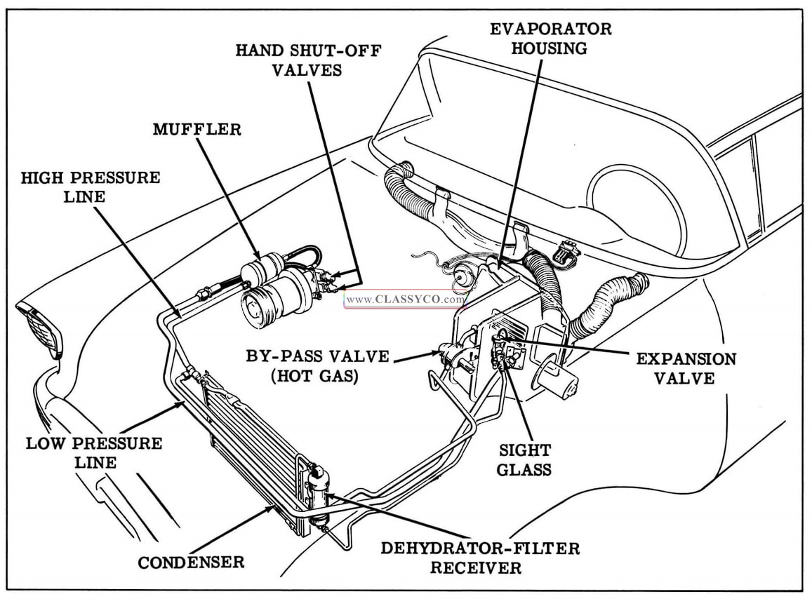
1957 Oldsmobile Freon System Unit Location
COMPRESSOR
The refrigeration system uses an axial type compressor. It is a reciprocating compressor having five cylinders, with intake and discharge valve reeds for each cylinder. These valve reeds cause the compressor to have a definite separation between the discharge (high) side and the intake (low) side. A small amount of oil is picked up by the Freon in the compressor and is pumped through the refrigeration system. An oil test fitting is on the lower side of the compressor. The solenoid operated clutch pulley permits the compressor to run only when refrigeration is desired. The only items to be serviced are the clutch pulley assembly, solenoid, and the compressor shaft seal and seat. Do not tighten the twelve compressor flange bolts to correct leaks at flange. If leaks occur at this point, the compressor should be re turned to Frigidaire.
COMPRESSOR PRESSURE RELIEF VALVE
The compressor is equipped with a pressure relief valve which is placed in the system as a safety factor. Under certain conditions, the refrigerant on the high side may exceed a safe operating pressure. Therefore, to prevent damage, the valve is designed to open automatically at ap proximately 415 p.s.i. Any condition that causes this valve to open should be corrected, and the refrigerant oil and Freon should be replenished as necessary.
COMPRESSOR HIGH AND LOW PRESSURE VALVES (HAND SHUT-OFF)
The compressor inlet and outlet lines attach to shut-off valves on the outside of the compressor. These valves are necessary to permit pressure checks and servicing of the Freon system.
The compressor high and low pressure valves are two way valves. When turned completely counter-clockwise, the passage to the compressor is connected to the refrigerant line, but sealed from the gauge fitting. (See Fig. 14-6) This is the normal operating position.
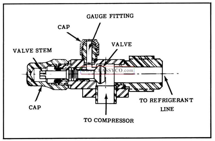
1957 Oldsmobile Compressor Valve
When the valve stems are turned completely clockwise, the passages to the refrigerant lines are sealed, and the passages to the gauge fittings are opened. In this position, the evaporator and condenser are shut off from the compressor and the compressor can be removed or serviced.
CAUTION: NEVER OPERATE THE COMPRES SOR WITH THE HIGH PRESSURE VALVE CLOSED (FULLY CLOCKWISE).
When the valve stems are turned to the middle position, both the passages to the gauge fittings and to the compressor are open. This permits pressure gauge readings while operating the system.
NOTE: The high pressure valve is the upper valve; the low pressure valve is the lower one.
The valves are serviced as an assembly and are sealed at the compressor by means of two “O” rings.
COMPRESSOR MUFFLER
A muffler has been placed in the high pressure side of the system to reduce compressor noises and high pressure line vibrations. The muffler tank absorbs the surges from the compressor in a manner similar to the action of a hydraulic accumulator. No repairs are to be made on the muffler. If it is defective, it should be replaced. Always install the muffler with the outlet side down.
CONDENSER
The condenser is similar to the ordinary car radiator. It is made up of coils which carry the Freon, and cooling fins which provide rapid trans fer of heat. The condenser is located in front of the engine cooling system radiator so that it receives a high volume of air from the movement of the car and from the engine fan. The air passing through the condenser cools the high pressure Freon vapor, causing it to condense into liquid Freon.
SIGHT GLASS
The Freon sight glass is provided to aid in diagnosis, by permitting the Freon in the high pressure line to be observed. The appearance of bubbles or foam, after the compressor has run long enough to stabilize, indicates a shortage of Freon.
DEHYDRATOR-FILTER RECEIVER ASSEMBLY
The functions of this unit are to absorb moisture and foreign material that may be present in the system after assembly, and to insure a solid column of liquid Freon in the line feeding the expansion valve, providing the system is properly charged. This unit is not serviceable, and should be replaced when there has been a leak in the low pressure side of the system that permitted air and moisture to be drawn into the system.
EXPANSION VALVE (Fig. 14-7)
The expansion valve, mounted outside the evaporator housing, controls the flow of Freon into the evaporator. It is adjusted so that the temperature of the Freon at the evaporator outlet must be 6°F. higher than the temperature of the Freon at the inlet before more Freon is allowed to enter the evaporator. A capillary tube filled with carbon dioxide provides the temperature regulation of the expansion valve. The capillary tube is fastened to the low pressure Freon line ·coming out of the evaporator so that it communicates the temperature of the Freon at this point to the expansion valve. If the temperature differential between the inlet and outlet decreases toward 6°F., the expansion valve will automatically reduce the amount of Freon entering the evaporator, thus reducing the amount of cooling. If the temperature differential increases, the expansion valve will automatically allow more Freon to enter the evaporator, thus increasing the cooling. The only service operations to be performed on the expansion valve are the cleaning and/or replacement of the inlet filter screen.
NOTE: It is very important that the expansion valve capillary tube bulb be tightly clamped to the low pressure Freon line coming out of the evaporator for proper operation. Both the low pressure line and capillary tube should be cleaned at the points of contact.
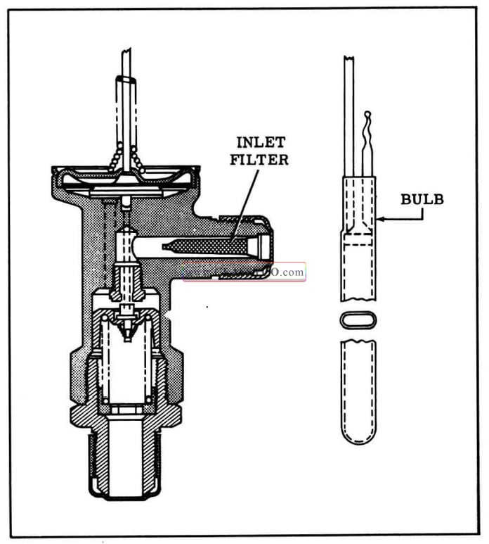
1957 Oldsmobile Expansion Valve
EVAPORATOR ASSEMBLY (Fig. 14-8)
The evaporator housing contains the evaporator core (cooling coils), fresh air valve, recirculating air valve, blower, and motor.
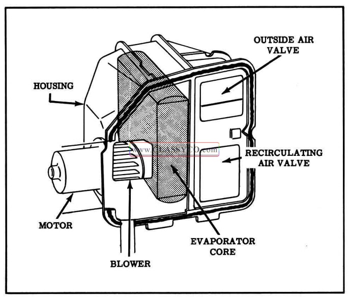
1957 Oldsmobile Evaporator Assembly
Cleaning Evaporator Core
To clean evaporator core, remove the plate from the low pressure line inlet, insert a water hose, and wash the core.
FREON “HOT GAS” BY-PASS VALVE (Fig. 14-9)
The Freon by-pass valve performs two functions in the refrigeration circuit. First, it acts as a temperature control and secondly it limits the evaporator minimum pressure to prevent “freezing-up” of the evaporator coils. The valve serves as a temperature control, being linked directly to the instrument panel control by a control cable. As shown in Fig. 14-9, the by-pass valve is wide open in the left hand refrigeration position of the control and in that position it maintains high evaporator pressure. The farther to the right the temperature control is positioned, the lower the evaporator pressure will become and thus the car will become cooler. The by-pass control cable adjustment is of extreme importance to insure proper operation in all control positions.
When the control is moved fully to the right, the by-pass valve is set to maintain low evaporator pressure (29.5 p.s.i.) which results in maximum cooling ability of the evaporator and consequently maximum cooling of the discharge air. The evaporator minimum pressure is limited by automatically injecting “Hot Freon Gas” into the upper tank of the evaporator core. This action takes place when the evaporator pressure tends to drop below 29.5 p.s.i.
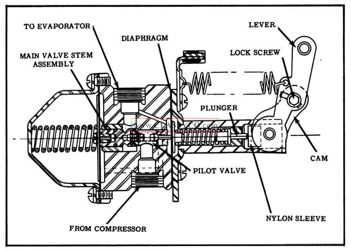
1957 Oldsmobile Hot Gas By-Pass Valve
REFRIGERATION CIRCUIT (Fig. 14-10)
Heat laden, low pressure vapor is drawn into the compressor and pumped from the compressor through the muffler to the condenser under high pressure. The vapor is heated as a result of the compression process. As it passes through the condenser, the high pressure – high temperature vapor is cooled, which causes the vapor to con dense into liquid Freon. The liquid Freon passes from the condenser into the dehydrator-filter receiver which acts as a reservoir. The liquid in the receiver is still under high pressure.
Liquid Freon from the receiver passes through the sight glass to the expansion valve. The expansion valve meters Freon into the evaporator core. When the pressure in the evaporator is reduced to 29.5 p.s.i. for maximum cooling, the liquid Freon immediately begins to boil at ap proximately 32°F. as it enters the evaporator. As the Freon passes through the evaporator, it continues to boil at 32°F., drawing heat from (and thereby cooling) the air passing through the evaporator core. By the time the Freon leaves the evaporator, it has completely vaporized and has warmed approximately 6 F.
Freon returns from the evaporator through the low pressure line to the compressor. When the evaporator pressure drops below 29.5 p.s.i. the Freon by-pass valve partially opens to permit “Hot Gas” from the compressor to enter the upper tank of the evaporator core to prevent freezing of the core. It is this same action that regulates the amount of cooling when the control on the instrument panel is moved to a warmer position. By pass valve action maintains higher evaporator pressures and warmer discharge air.
On a cold day, the system will by-pass almost constantly. As the ambient (atmospheric) temperature becomes higher, the by-pass system will work less and less.
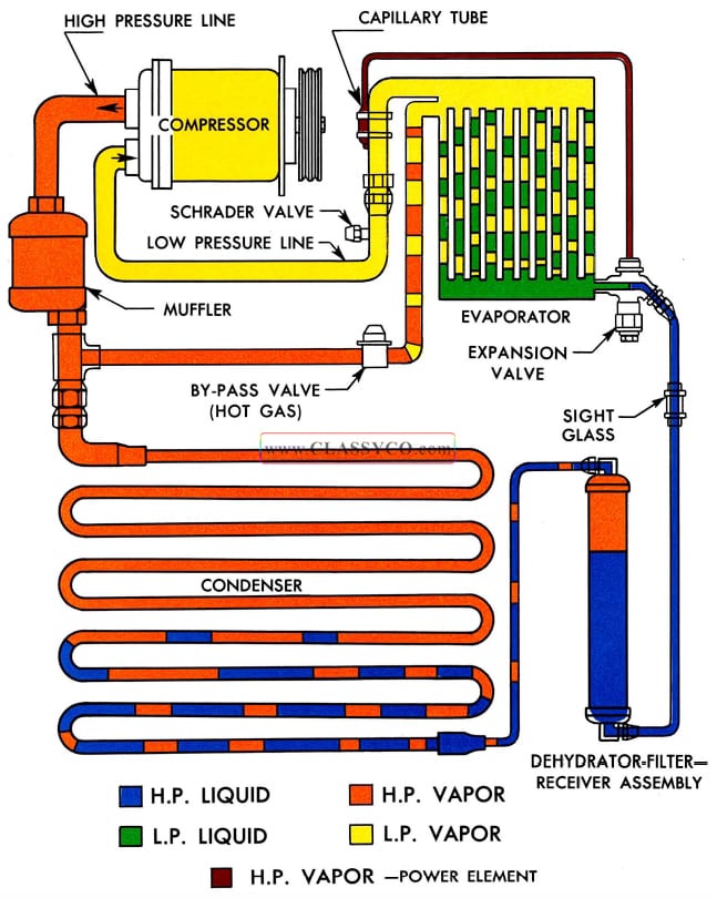
1957 Oldsmobile Refrigeration Circuit
PRECAUTIONS IN HANDLING FREON 12
Do Not Leave Freon Drum Uncapped
All refrigerant drums have a metal screw cap. This CAM protects the valve and safety plug from damage; therefore, the protective cap should always be replaced when the drum is not in use.
Do Not Subject Drum to High Temperature
The drum should not be exposed to the radiant heat of the sun, for the resulting increase in pressure may cause the safety plug on the drum to burst.
The freon drum should never be subjected to excessive temperature when charging a system. The Freon drum should be heated for charging purposes placing in 125°F. water. Never heat above 125 F. or use a blow torch, radiator, or stove to heat the drum.
Do Not Weld Or Steam Clean
On or Near the System
Welding or steam cleaning of, or near, any of the refrigerant lines or components of the refrigerant system can build up dangerous pressures in the system.
Do Not Fill The Drum Completely
When filling a small drum from a larger one, always allow space above the liquid for expansion. If the drum were completely filled and the temperature increased, tremendous hydraulic force would develop.
Do Not Discharge Vapor Into Areas
Having Exposed Flame
Large quantities of Freon 12 should not be dis charged into a closed room. The Freon may dis place the oxygen in the air. Also, heavy concentrations of Freon 12 in contact with a live flame, such as a gas heater, will produce a poisonous gas. This gas will also tarnish all bright metal surfaces.
Do Not Expose Eyes To Freon
One of the most important precautions is protection of the eyes when handling Freon. Any liquid Freon which may accidentally escape is approximately 2!”.7°F. below zero. If any Freon comes in contact with the eyes, serious damage could result. Always wear goggles to protect the eyes when handling Freon.
If Freon should come in contact with the eyes, here is what to do:
- DO NOT rub the eye. Splash the affected area with quantities of cold water to gradually get the temperature above the freezing point.
- Apply a protective film of an antiseptic oil over the eye ball to reduce the possibility of infection.
- Consult a doctor or an eye specialist immediately.
Should liquid Freon come in contact with the skin, the injury should be treated the same as though ‘the skin has been frostbitten or frozen.
MAINTAINING CHEMICAL STABILITY IN THE REFRIGERATION SYSTEM
The efficient operation of the air conditioning refrigeration system is dependent on the pressure temperature relationship of pure Freon 12. As long as the system contains pure Freon 12 (plus a certain amount of compressor oil which mixes with the Freon), it is considered to be chemically stable.
When foreign materials, such as dirt, air, or moisture, are allowed to get into the system, they will effect chemical stability, cause the expansion valve to freeze up, and change the pressure temperature relationship of the Freon. Thus, the system will no longer operate at the proper pressures and temperatures, and the efficiency will decrease.
The following general practices should be observed to insure chemical stability in the system:
Keep Tubing Sealed
Whenever it becomes necessary to disconnect a refrigerant line, it should be immediately capped. Air that enters any part of the system will carry moisture with it and the exposed surfaces will collect the moisture quickly. Capping the lines will also prevent dirt and foreign matter from entering.
Keep Tools Clean
Tools should be kept clean and dry. This includes the gauge set and replacement parts. Keep gauge lines plugged.
Use Clean Dry Oil Container
When adding oil to compressor, the container should be exceptionally clean and dry due to the fact that refrigeration oil is as moisture-free as possible; therefore, it will quickly absorb any moisture with which it comes in contact.
Keep Oil Container Capped
The oil container should not be opened until ready for use and should be capped immediately after use to reduce the possibility of the oil absorbing moisture.
Do Not Keep System Open Longer Than Five Minutes
PRECAUTION IN HANDLING LINES
All replacement lines must be checked to see if they are completely sealed and dehydrated. Freon lines must be free of kinks which would restrict the flow of refrigerant.
Freon line insulated clamps are used to reduce vibration and it is important to reinstall all the clamps when a line is replaced. Tightening flare connections is very important and the proper size wrenches should be used. Copper flares are relatively soft; consequently, a great amount of pressure against the seat is NOT required. The op posing fitting should always be held with a wrench to prevent distortion of connecting lines or com ponents. ALWAYS USE TWO WRENCHES WHEN TIGHTENING OR LOOSENING FREON LINE FIT TINGS. Flares and flare seats should be coated with refrigeration oil before they are assembled to permit the flares to seat squarely and provide for proper tightening.
When disconnecting any fitting in the refrigeration system, proceed very cautiously regardless of gauge readings. Open very slowly, keeping face and hands away so that no injury can occur if there happens to be liquid Freon in the line. If pressure is noticed when fitting is loosened, allow it to bleed off very slowly.
CAUTION: ALWAYS WEAR SAFETY GOG GLES WHEN OPENING REFRIGERANT LINES.
In the event any line is opened to atmosphere, it should be immediately capped to prevent entrance of moisture and dirt.
SPECIAL EQUIPMENT (Fig. 14-11)
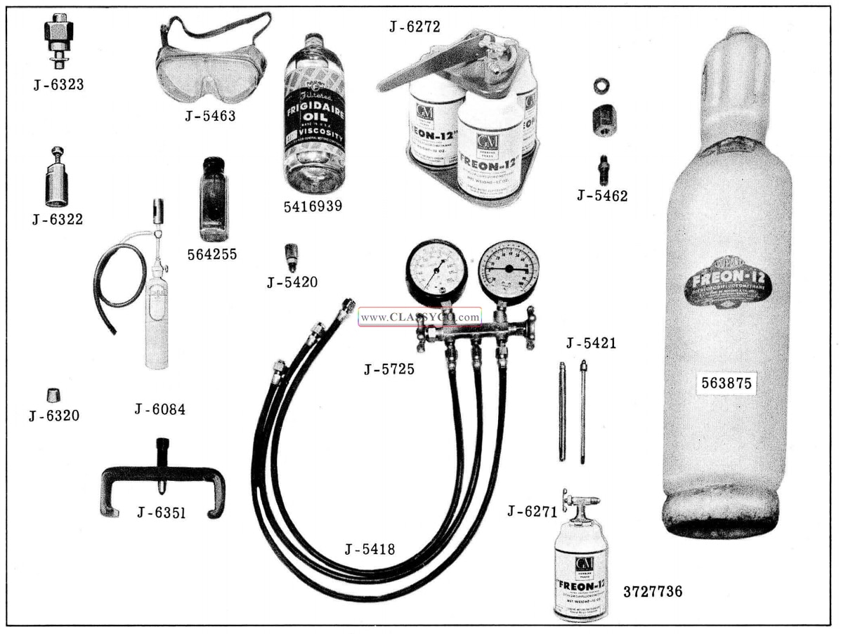
1957 Oldsmobile Refrigeration Service Equipment
REFRIGERATION GAUGE SET (Fig. 14-12)
The gauge set is used when purging, evacuating, charging, or diagnosing trouble in the system. The low pressure gauge is graduated into pounds of pressure from 0 to 100 and in the opposite direction in inches of vacuum from 0 to 30. The high pressure gauge is graduated from 0 to 300 pounds pressure. The center connection is common to both and is for the purpose of attaching a line for adding Freon or evacuating the system. When this connection is not required, it should be capped with a flare nut and cap.
The hand shut-off valves close each opening to the connector and to each other. They DO NOT open or close off pressure to the gauges.
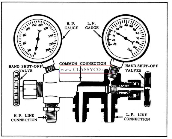
1957 Oldsmobile Gauge Set
LEAK DETECTOR (TORCH)
The leak detector is used to locate a leak in any part of the Freon system. To operate, the detector is ignited and the sampling tube is held close to all possible points of leakage (fittings, connections, etc.). If the flame changes color, particularly green, brilliant blue, or purple, Freon is being drawn into the sample tube, indicating a leak.
CAUTION: DO NOT BREATHE THE FUMES THAT ARE PRODUCED BY THE LEAK DE TECTOR AS THEY ARE POISONOUS.
CAUTION: The valve should never be closed tightly when the needle is hot because the needle will “freeze” when the burner cools and the valve seat will be damaged.
LEAK DETECTOR (LIQUID)
There are a number of fittings and places throughout the air conditioning unit where leak detector solution (Part No. 564255) may be used to pin-point leaks.
Apply the solution to the suspected area with a swab that is attached to the bottle cap. Bubbles will form within seconds if there is a large leak.
For confined areas, such as sections of the evaporator and condenser, the alcohol torch or a Bernz-O-Matic torch is the only method which can be used.
VACUUM PUMP
The vacuum pump is recommended as a service tool. If a leaking system has been operated in a discharged condition, the receiver-dehydrator filter assembly should be replaced and a vacuum pump should be used to thoroughly evacuate the system.
SERVICING OF INDIVIDUAL UNITS (NOT IN FREON SYSTEM)
The following services and repairs concern parts of the air conditioning system which can be serviced without opening the Freon system.
COMPRESSOR BELT ADJUSTMENT
Tool 33-70 is used to check the compressor belt tension. (See Fig. 14-13)
If belts need to be adjusted:
- Loosen generator adjusting link bolt and bracket pivot bolts.
- Place Tool 33-70 on one belt.
- Pry generator away from engine until the pointers on Tool 33-70 are even with the line on the tool plunger.
- Tighten generator link bolt and pivot bolts.
- Check both belts. If either belt is outside of the gauge limits, replace both belts and re adjust as above.
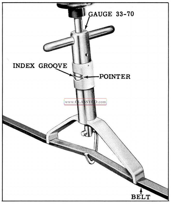
1957 Oldsmobile Adjusting Compressor Belts
AIR OUTLETS
Adjustment (Fig. 14-14)
Nozzles should be free to rotate but tight enough to remain in a set position. If the tension is insufficient, the felt must be replaced. To remove the nozzle; first remove the air hose, then tap the nozzle from the bezel with a wood block.
To replace felt seat, make sure sea ting surface is clean; then cement felt seat in place using 3 -M Super Weatherstrip Adhesive. To replace the out let nozzle, place the retainer spring into the nozzle groove and press the nozzle into the bezel until it locks.
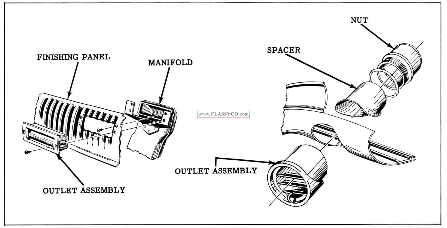
1957 Oldsmobile Outlet Assemblies
Replacement
To replace the air outlet assembly, remove air hose and unscrew the large threaded air inlet nut on the back of the instrument panel. Pull the assembly from instrument panel.
COMPRESSOR CLUTCH SWITCH
Adjustment
The compressor clutch switch is actuated by the sliding lever in the control assembly. The switch should close when the lever is moved 1/4″ from the extreme left position. If necessary to adjust the switch, bend the switch bracket as shown in Fig. 14-15.
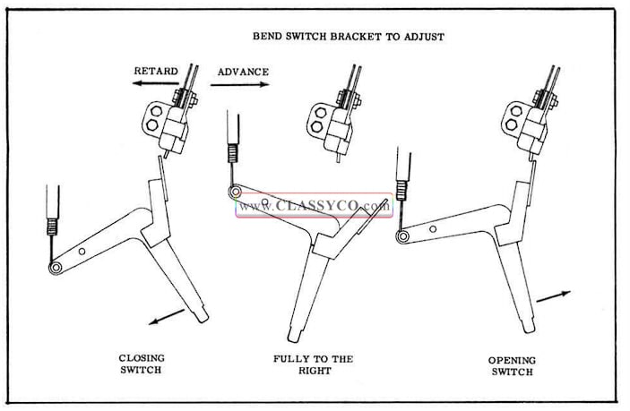
1957 Oldsmobile Clutch Solenoid Switch Adjustment (Bottom View)
CONTROL ASSEMBLY
Remove and Install
- Remove blower speed switch knob and temperature control lever knob.
- Remove air manifold.
- Remove the two control attaching stud nuts.
- Push control forward through cluster and low er.
- Remove Bowden cable from control.
- Remove vacuum hoses and wires from control assembly.
- To install, reverse removal procedure.
Refer to schematic diagrams (Fig. 14-37 and 14-38) for proper installation of hoses.
“HOT GAS” BY-PASS VALVE CABLE ADJUSTMENT (Fig. 14-16)
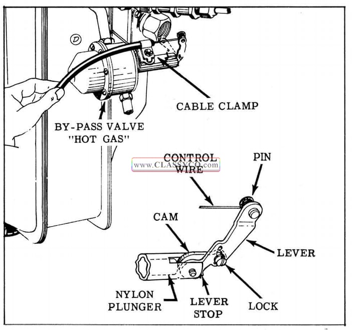
1957 Oldsmobile By-Pass Valve Cable Adjustment
- Check to insure cable is not kinked and operates freely, then disconnect return spring.
- Place the control lever in the extreme right position. (See Fig. 14-17)
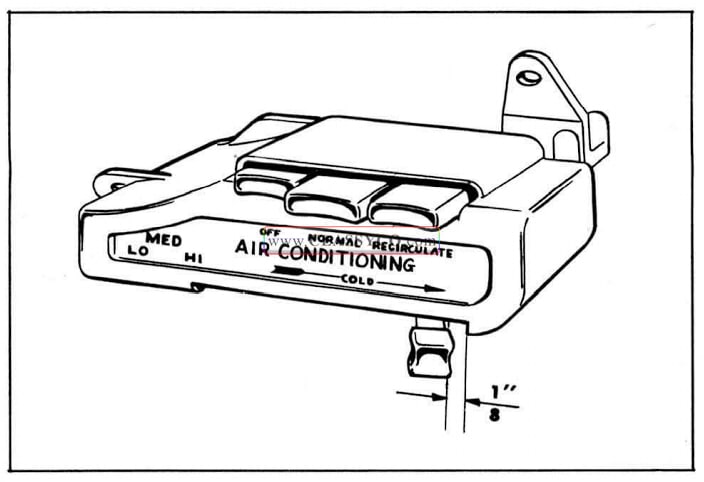
1957 Oldsmobile Control Lever Position
- Disconnect the control cable from the lever and loosen the control cable clamp on the by pass valve bracket.
- Loosen the lock screw on the lever assembly.
- With the lever against stop, position the cam so that it just touches the nylon plunger. Tighten the lock screw in this position.
- With the by-pass lever held against its stop, install the control wire coil over the lever pin and, while pushing the cable conduit toward the lever to remove slack, tighten the cable clamp. install return spring.
- Move the control to the left and back to the extreme right position. There should now be 1/16″ to 3/32″ spring-back of the lever. Again check to make sure that the cam is just touching the nylon plunger.
BLOWER MOTOR
The blower motor assembly is mounted on the left side of the evaporator housing. To remove the motor and/or the blower, the left hood hinge has to be removed. (See CHASSIS SHEET METAL Section) The assembly is retained by five sheet metal screws and no sealer is required at the mounting flange. The ground wire is retained by a blower motor attaching screw and the positive lead terminal is plugged into a plastic connector which is clipped onto the hood hinge support.
CLUTCH AND PULLEY ASSEMBLY
Clutch Adjustment (Fig. 14-18)
- Energize clutch coil by manually closing master switch located on evaporator and moving temperature lever to “ON” position.
- With feeler gauge, check air gap between clutch plate and housing. This air gap should be.025″ to.035″. If the air gap is not within these specifications, it will be necessary to remove the clutch and add or subtract shims. These shims come in four thicknesses:.010″,.015″,.020″,.025″, and by proper selection of these shims,.005″ variation in air gap can be obtained.
NOTE: There are two sets of shims in the clutch. One set is forward and the other is to the rear of the clutch plate assembly. DO NOT remove shims from the forward set. This set controls the spacing (.008″ to.013″) between the clutch friction facing and its mating surface on the pulley.
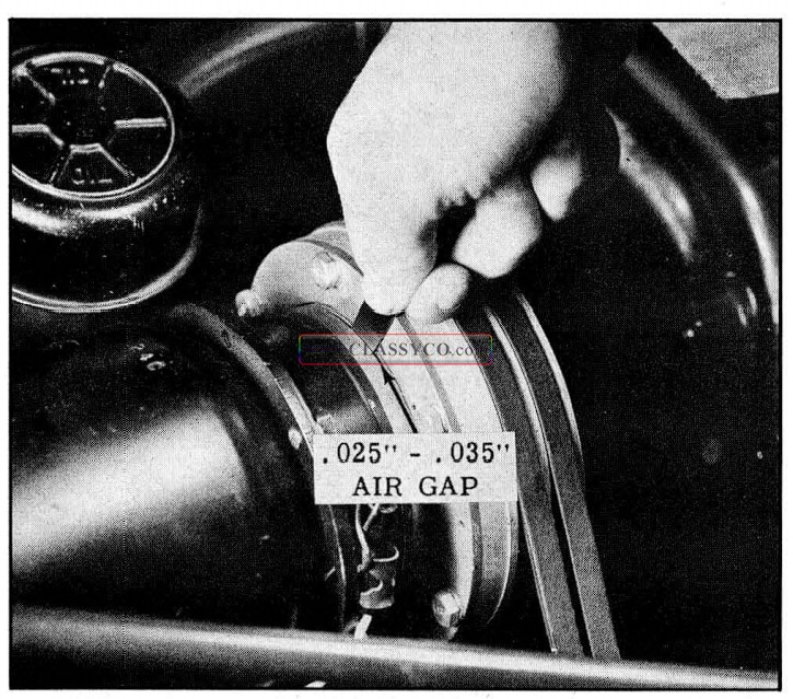
1957 Oldsmobile Checking Inner Clutch Plate Air Gap
Pulley and Clutch Removal (Fig. 14-19)
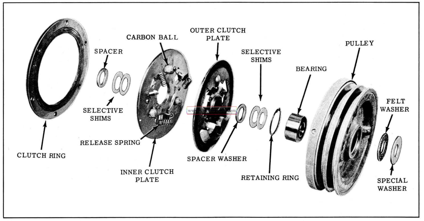
1957 Oldsmobile Pulley And Clutch Assembly
NOTE: If clutch and pulley removal is due to suspected malfunction of the clutch, the air gap between the clutch plate and the coil housing should be checked before the assembly is removed.
- Energize compressor clutch coil long enough to permit removal of the compressor shaft nut after straightening lock tangs.
NOTE: to energize coil manually, close the mast er switch on evaporator and move temperature control to “ON” position. Remove nut, lock, and washer with felt from the compressor shaft.
- Remove the 3 coil retaining screws from the coil housing.
- Remove the 6 clutch ring attaching screws, lockwashers and locks, and position the clutch ring rearward.
- Using Tool J-6351, remove pulley. (See Fig. 14-20)
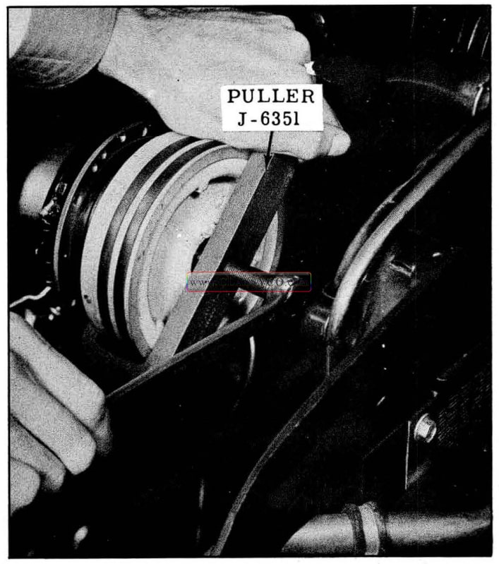
1957 Oldsmobile Pulley Removal
- Remove spacer washer and shims from compressor shaft
IMPORTANT: The shims should be reinstalled upon assembly if the same pulley and clutch are to be reinstalled.
- Thread Tool J-6322 onto hub of clutch assembly. While holding the tool with a wrench, tighten the tool bolt to remove clutch assembly. (See Fig. 14-21) Remove Tool J-6322 from the clutch hub.
- If selective shims or spacer are to be removed, remove the Woodruff key.
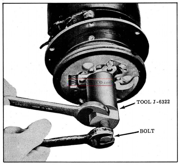
1957 Oldsmobile Clutch Removal
Pulley to Clutch Plate Clearance
If it is necessary to replace clutch plates, pulley, or bearing or if the parts are being assembled on a service replacement compressor, a different com bination of shims may be required to obtain .008″ to.013″ clearance between the friction material on the clutch plate and pulley face, with the clutch disengaged.
NOTE: This clearance must be obtained before the clutch assembly and the pulley are pressed onto the shaft.
To obtain the clearance, proceed as follows:
- Place the pulley (with bearing installed) on a flat surface with clutch side of pulley facing up.
- A combination of the following shims;.010″, .015″, .020″ and .025″, when used with the bearing spacer washer, will permit an .008″ to .013″ clearance.
- Select a combination for trial use, and place these shims on the inner race of the bearing, then place the bearing spacer on the shims. Place the clutch plate assembly in the pulley so that the hub is in contact with the spacer and shims.
- Press down firmly at the center of the hub. Rotate the clutch plate assembly. If a HEAVY “drag” is felt, thicker shims must be selected in order to provide a VERY slight “drag”. If no “drag” is felt, thinner shims should be selected, so as to obtain a VERY slight “drag”. When this condition is obtained, determine the total thickness of the shims assembled. Either add an additional.010″ shim or replace one of the shims with a .010″ thicker shim which will provide .008″ to .013″ clearance between the outer clutch plate and the pulley.
Pulley and Clutch Installation
- Remove the clutch ring from coil housing and, while pressing on coil retainer, install the three coil retaining screws.
- With spacer, shims, and Woodruff key installed, position clutch assembly, with clutch ring held against inner clutch plate, on compressor shaft. (Counterweight facing away from compressor.)
- Place washer of Tool J-6322 on the compressor shaft with the chamfered side facing the clutch assembly.
- Thread the bolt of Tool J-6322 onto the com pressor shaft and, while holding the bolt, turn the nut counter -clockwise until the clutch assembly seats against the spacer and shims. (See Fig. 14-22) Remove the tool and washer.
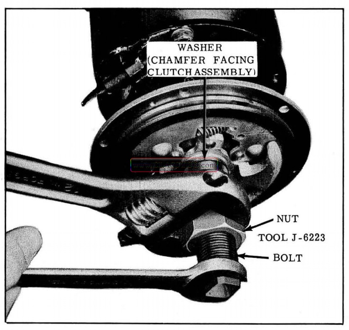
1957 Oldsmobile Installing Clutch
- Place the pulley spacer against the clutch hub, install the shims, and then start pulley on compressor shaft. Place the washer of Tool J-6322 over the tool bolt with the chamfered side away from the tool. Thread tool bolt onto compressor shaft. While holding the tool bolt, turn the tool nut counter-clockwise to press the pulley onto the compressor shaft. (See Fig. 14-23)
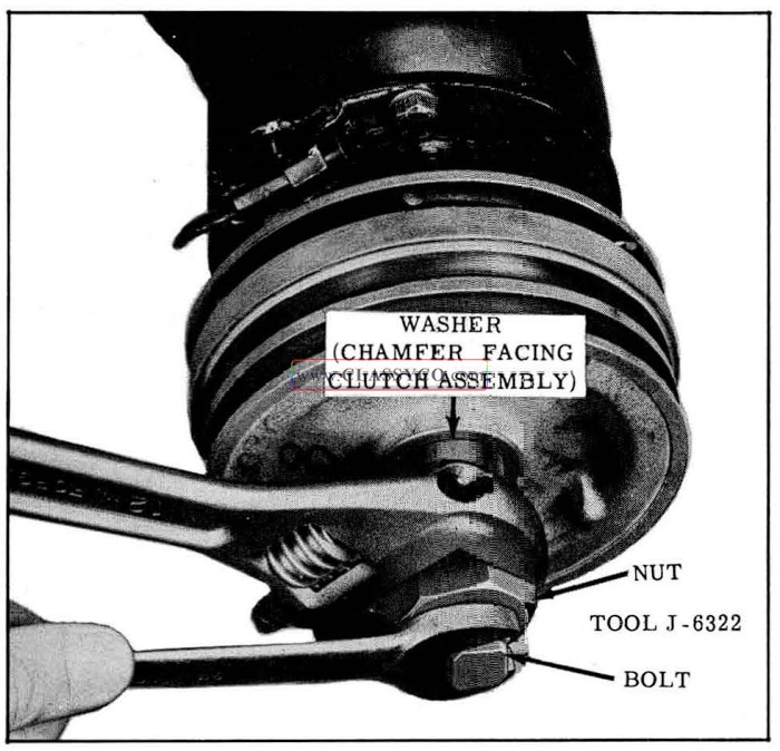
1957 Oldsmobile Installing Pulley
- Install special washer and felt washer, with hub of washer and felt facing the pulley, over the compressor shaft.
- Install lock, with tang facing in, and nut on compressor shaft. (Do not torque at this time.)
- Install the 6 clutch ring to pulley cap screws, with locks and lockwashers, and torque 2 ft. lbs.
- With the clutch coil energized, torque the compressor shaft nut 5 to 7 ft. lbs.
- Check clutch air gap. The air gap must be.025″ to.035″. (See Fig. 14-18)
- Install and adjust compressor belts using Tool 33-70.
PULLEY BEARING
Removal
- Remove pulley.
- Remove bearing retainer ring from groove in pulley cavity using No. 3 Tru-Arc pliers.
- Remove bearing from pulley hub.
NOTE: If pulley hub shows evidence of w ear due to outer race of bearing rotating in hub, replace pulley.
Installation
- Install new bearing into pulley by pressing on outer race of bearing.
- Install retainer ring, (chamfer out) then install pulley.
- Check clutch air gap.
CLUTCH
Disassembly
- Remove the 3 clutch release springs by disengaging springs from spring seats.
CAUTION: Clutch springs are under moderate tension, therefore care should be exercised in removal.
- Separate clutch plates and remove 3 carbon balls.
Cleaning and Inspection
CAUTION: Do not clean the clutch assembly with cleaning solvent. Parts should be cleaned with a clean, dry, oil-free cloth. Examine carbon balls, tear-drop depressions, and friction surf aces of clutch plates. If the carbon balls are deformed, excessively worn, or damaged they should be replaced. The clutch release springs may be replaced if necessary. If the clutch surfaces are worn or tear-drop depressions are deformed, the clutch plates must be replaced.
To assemble, place the rear clutch plate (lining side down) on a bench, place the carbon balls in the tear-drop depressions, place the clutch plate (with the counterweight up) over the carbon balls, and install the springs over the spring seats.
CLUTCH ACTUATING COIL (Fig. 14-24)
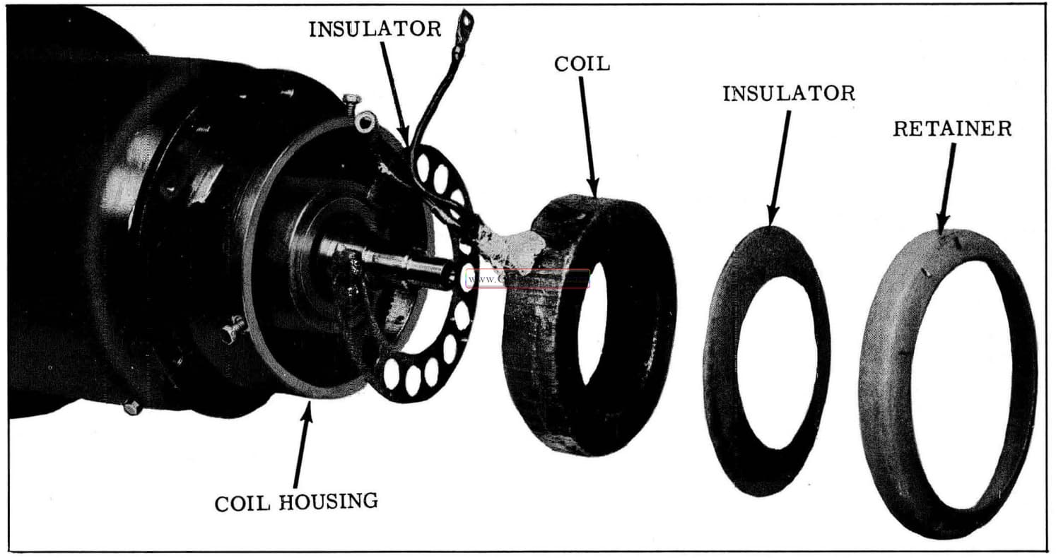
1957 Oldsmobile Clutch Coil Assembly
Removal
- Remove the pulley and the clutch.
- Remove clutch ring from coil housing.
- Remove Woodruff key, shims and spacers from the compressor shaft.
- Remove the coil retainer and insulator.
- Disconnect the lead-in wire and remove the lead-in terminal, ground wire screws, and the coil wire retaining clamp from the compressor flange.
- Remove the coil and insulator from coil housing, taking care not to damage the coil.
- Inspect insulators and replace if damaged.
Installation
- Place the inner insulator in the coil cavity with the opening aligned with the opening in the housing.
- Route coil leads through opening in coil housing and install coil.
- Install retaining clamp, connect ground wire, and connect positive leads to the connector. Attach connector bracket to compressor flange.
- Install paper insulator with the dished side toward the coil.
- Install coil retainer over coil insu1ator with dished side toward coil and press firmly in place while installing the 3 retainer screws.
- Install spacer washer, shims and Woodruff key.
- Place the clutch ring over the inner clutch plate and install the clutch assembly on compressor shaft. (See Fig. 14-22)
- Install the pulley. (See Fig. 14-23)
- Install compressor belts and adjust tension using Tool 33-70.
- Energize clutch coil and torque compressor shaft nut 5 to 7 ft. lbs.
- Check the air gap between the clutch and the housing. Air gap must be .025″ to.035″.
SERVICING OF THE FREON SYSTEM
In removing and replacing any part in the Freon system except the compressor, the following operations must be performed.
- Purge the system by releasing the Freon to atmosphere.
- Remove and replace the defective part.
- Evacuate the system of air and moisture.
- Charge the system with Freon-12.
PURGING THE SYSTEM
- With the engine stopped, remove protective caps from compressor high and low pressure hand shut-off valves. (See Fig. 14-25)
- Make sure both valves are turned fully counter clockwise; this is to assure that gauge outlets are closed.
- Remove caps from both gauge outlets on compressor.
- Crack open (turn clockwise) high and low pressure hand shut-off valves on compressor and allow Freon to escape from the system.
CAUTION: Do not open valves beyond cracking point or compressor oil may be discharged with the Freon.
The complete system has now been purged of Freon and any part in the refrigeration system can be replaced.
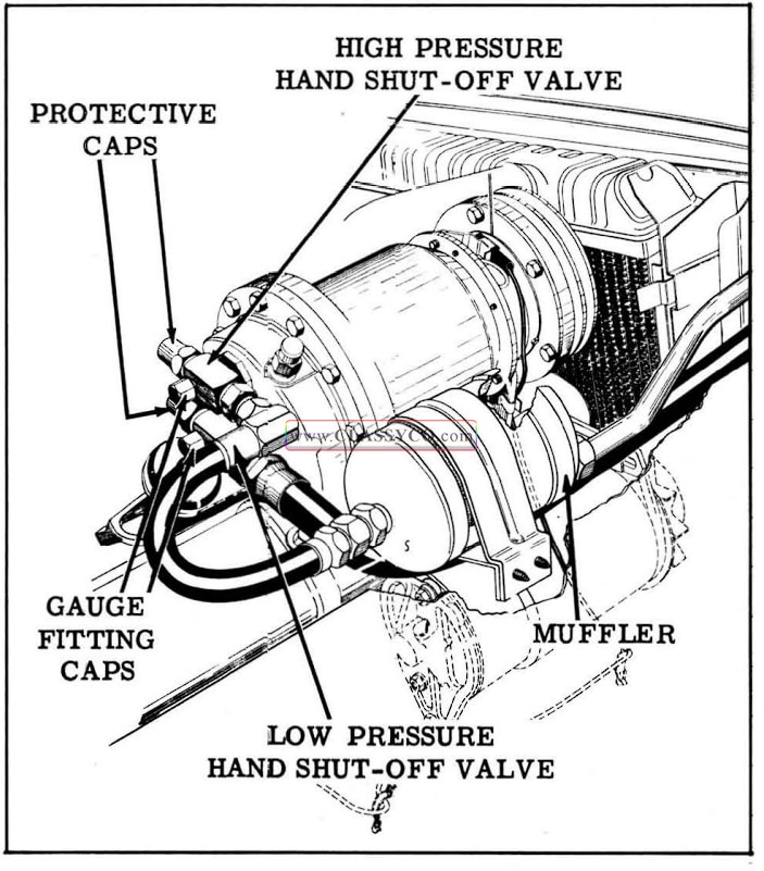
1957 Oldsmobile Shut-Off Valves
EVACUATING THE SYSTEM
- Have gauge set and Freon drum connected as shown in Fig. 14-26.
- Turn compressor high pressure hand shut-off valve fully clockwise. Turn compressor low pressure hand shut-off valve fully counter clockwise, then two turns clockwise. Replace end caps and tighten.
CAUTION: Leave compressor high pressure gauge outlet cap off.
- Close high pressure gauge valve and open low pressure gauge valve.
- Set refrigeration temperature control lever fully to the right, start engine and allow to run at slow idle to obtain a vacuum of 28″ for 5 minutes.
NOTE: Position a container to receive any oil discharged from the high pressure gauge outlet so that an equivalent amount of new oil can be added.
- While engine is running, install cap on compressor high pressure gauge outlet.
- Stop engine and observe if 28″ vacuum will hold for 3 minutes.
- Open valve on Freon drum and allow system to charge up to drum pressure; then close valve on Freon drum.
- Again purge the system through the compressor high pressure gauge outlet, by removing gauge outlet cap. After system is purged, start the engine. Allow to run at slow idle to obtain a vacuum of 28″ for 5 minutes.
- While engine is running, install cap on com pressor high pressure gauge outlet, then stop the engine.
NOTE: This second evacuation is to eliminate any air or moisture that might have remained in the system.
- Place Freon drum on scales and weigh accurately. This is to determine amount of Freon used to bring the system up to drum pressure and to complete the full charge of Freon. Set drum in a pail of water at not more than 125° if desired. (If pail of water is used, weigh it with Freon drum.)
- Open valve on Freon drum to charge system to drum pressure.
- Turn compressor high pressure hand shut-off valve fully counter-clockwise and remove gauge outlet cap.
- Crack open compressor high pressure hand shut-off valve to purge outlet, crack open high pressure gauge valve to purge hose, and connect hose to compressor while purging.
- Turn compressor high pressure hand shut-off valve clockwise two turns, then close high pressure gauge valve.
The system is now ready for charging.
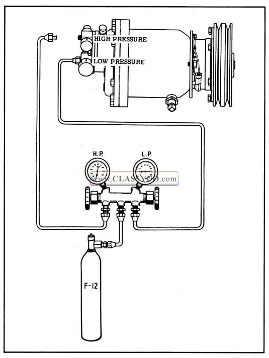
1957 Oldsmobile Evacuating the System
CHARGING THE SYSTEM WITH FREON
After the system is evacuated, leave the gauge set and Freon drum connected for the charging process. Make sure the high pressure gauge valve is closed, the low pressure gauge valve is open, and the valve on the Freon drum is closed; then proceed as follows:
- Open valve on Freon drum to allow Freon to enter the system. Start the engine and operate at fast idle with the temperature control fully to the right and the “NORMAL” button engaged. Close low pressure valve in gauge set at frequent intervals to be certain pressure in the low side is always maintained above 5 p.s.i.
- When 4-7/8 lbs. of Freon has entered the system, close the Freon drum valve and the low pressure gauge valve.
- Turn both compressor hand shut-off valves fully counter-clockwise, remove the gauge set, and replace caps on hand shut-off valves and gauge fittings.
BY-PASS VALVE ADJUSTMENT (Fig. 14-27)
The “Hot Gas” by-pass valve is adjusted to regulate evaporator pressure so that it will not fall below 29 to 30 p.s.i. If it controls below 29 p.s.i., the evaporator will “ice-up” and refrigeration capacity will be reduced. If the valve controls higher than this pressure, an undesirable loss of refrigeration will occur and will be especially noticeable in extremely hot weather. This is be cause for each pound in pressure higher than 30 p.s.i., the discharge air temperature will be raised one degree. The controlling pressure of the valve can be checked and adjusted as follows:
- Remove cap from gauge fitting on the low pressure line near the evaporator assembly.
NOTE: This gauge fitting has a Schrader valve.
- Install adapter, Tool J-5420, on the low pressure gauge line and connect the adapter to the gauge fitting on the low pressure line.
- Purge the gauge and hose by opening the low pressure gauge valve for a few seconds.
- Start engine and allow to run at 2000 R.P.M. Move temperature control lever to the extreme right position, turn blower speed on “LOW” and engage “RECIRCULATION” button.
- Place paper in front of condenser to obtain a head pressure of 200 p.s.i.
- Observe pressure gauge and adjust valve only if pressure is not 29 to 30 p.s.i.
NOTE: If necessary to adjust the pressure setting, the control cable and the lever and cam will have to be disconnected from the by-pass valve in order to insert Tool J-6389 into the valve. (See Fig. 14-27) Aft er the valve pressure has been adjusted to 29.5 p.s.i. the control cable adjustment will have to be made. (Refer to BY-PASS CONTROL CABLE ADJUSTMENT)
- Turn adjusting screw clockwise to increase pressure; counter-clockwise to decrease pressure.
- Turn engine off, remove gauge hose from pressure fitting, and replace cap.
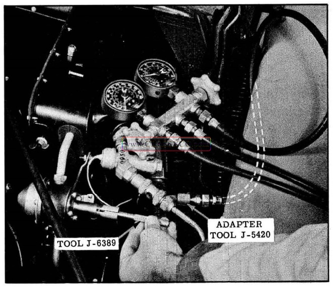
1957 Oldsmobile Hot Gas By-Pass Valve Adjustment
EVAPORATOR ASSEMBLY (Fig. 14-28)
NOTE: The expansion valve can be replaced without removing the evaporator assembly by following the instruction sheet in the expansion valve parts package.
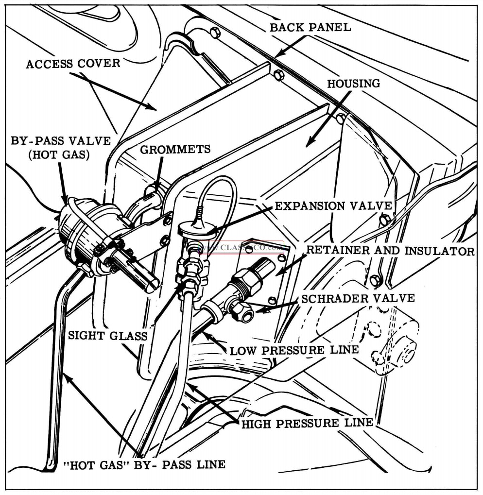
1957 Oldsmobile Evaporator Assembly (2)
Removal
- Purge Freon system as outlined und er PURGING THE SYSTEM.
- Disconnect vacuum hose at evaporator assembly.
- Disconnect by-pass valve cable.
- Disconnect battery.
- Disconnect blower motor wires and remove resistor from evaporator housing.
- Disconnect line clamps as necessary to permit disengagement of connections.
- Disconnect high pressure line from the expansion valve and the evaporator low pressure line at the evaporator, and remove the by-pass valve.
- Cap all limes immediately.
- Remove fender to body support rod and engine air cleaner.
- If car is equipped with power brakes, dis connect vacuum line from bracket and carburetor.
- Remove housing back panel to dash sheet metal screws and remove evaporator assembly.
NOTE: The lower area of the housing is retained by a wedge type bracket and the bracket screws do not have to be removed.
Disassembly (Fig. 14-29)
- Remove low pressure line insulator and retainer plate. Remove high pressure line grommet and the hot gas by -pass line grommet from housing.
- Remove expansion valve from evaporator high pressure line.
- Remove screws and Tinnerman nuts holding evaporator housing to back panel and mounting plate, then disengage back panel from housing to permit removal of capillary bulb and tube.
- Remove expansion valve and housing.
- Remove three screws holding evaporator mounting plate to the back panel.
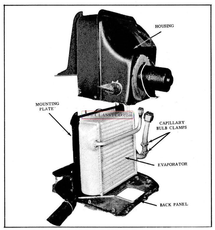
1957 Oldsmobile Evaporator and Housing
Assembly
- Install evaporator mounting plate to back panel with three screws.
- Scrape off old sealer and apply auto body sealer or equivalent to the evaporator housing flange.
- Route capillary tube through evaporator housing and tightly clamp capillary bulb on the evaporator low pressure line. Make sure line and bulb are clean and bright.
- Install the evaporator housing by lowering the housing over the pressure lines, making sure the tabs on the housing are in place over the mounting plate.
- Make sure the blower housing fits in the back panel opening, then install the housing-to-back panel attaching screws and Tinnerman nuts.
- Apply auto body caulking or equivalent between the blower housing and back panel opening.
- Install rubber grommets in housing around the high pressure and by-pass lines and install low pressure line insulator and retainer plate on the housing.
- Install expansion valve on evaporator high pressure line.
Installation
- Scrape old sealer from dash and apply auto body caulking compound or equivalent to the edge of the back panel. (See Fig. 14-30)
- Position housing on dash and install back panel-to-dash sheet metal screws.
- Remove caps from lines and connect high and low pressure lines.
- Attach line clamps.
- Connect blower motor wires and replace resistor on housing.
- Connect battery.
- Connect air valve diaphragm hoses.
- Connect by-pass valve cable.
- Adjust cable. Refer to CONTROL CABLE ADJUSTMENT.
- Replace fend er to body support rod and air cleaner.
- Connect vacuum line if car is equipped with power brakes.
- Evacuate the system as outlined under EVACUATING THE SYSTEM.
- Charge the system as outlined under CHARGING THE SYSTEM.
- Leak test all line fittings that w ere disconnected. Refer to LEAK DETECTOR.
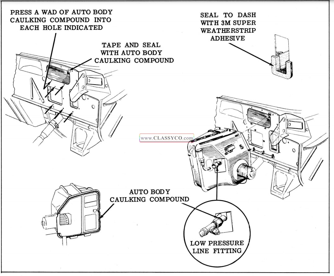
1957 Oldsmobile Sealing Areas
COMPRESSOR SEAL
Removal
- Remove caps from compressor high and low pressure hand shut-off valves.
- Turn both compressor hand shut-off valves fully clockwise to close the system and open compressor gauge outlets.
- Crack open compressor high pressure gauge outlet cap and allow Freon to purge until “hiss” is no longer heard.
- Remove clutch coil. Refer to PULLEY AND CLUTCH REMOVAL, AND COIL REMOVAL.
- Remove the 6 screws and pull the coil housing from the compressor.
- With the compressor shaft keyway facing up to avoid losing the drive pin, remove the wave washer and seal assembly.
- With a screwdriver inserted into the seal shell, pry the seal from the coil housing.
- From the compressor side of the coil housing, remove the snap ring, seal seat, and “O” ring.
- Remove the large “O” ring from the coil housing flange.
Cleaning and Inspection of Parts
Thoroughly clean the seal cavity and shaft with wiping tissues furnished in the seal package. DO NOT touch or mar the contacting face of the new seal or seal seat with hands or tools since this may damage the seals. All seals and “O” rings must be replaced with new parts.
Installation (Fig. 14-31)
- Flush the coil housing seal cavity with Frigidaire Oil No. 525.
- Install wave washer in recess of compressor flange.
- Install Tool J-6320 on the compressor shaft with the tapered end toward the front of the shaft. Align the seal drive pin and rotate the retaining ring to contact the pin to hold it in place.
- Coat the entire seal assembly with Frigidaire Oil and install the seal assembly, making sure the drive pin engages the keyway in the seal. (See Fig. 14-32)
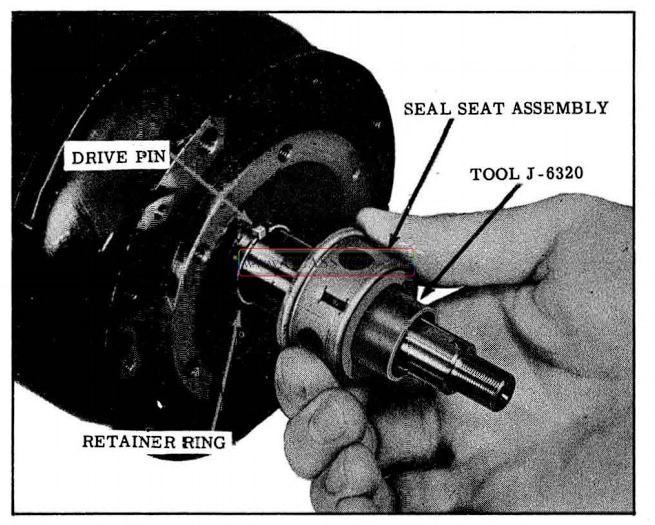
1957 Oldsmobile Installing Seal (2)
- Coat O.D. of auxiliary seal with Frigidaire Joint Compound and press seal into coil housing. (Seal lip must face compressor). (See Fig. 14-31)
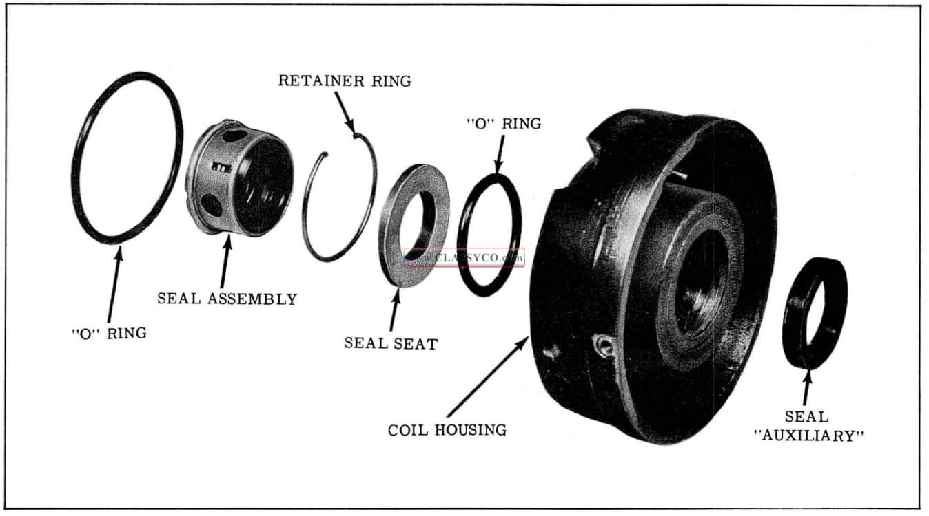
1957 Oldsmobile Compressor Seal Assembly
- Install the “O” ring into the seal cavity of the coil housing.
- Coat the seal seat with Frigidaire Oil and place into seal cavity with small diameter out so that it will face the compressor.
CAUTION: Do not touch sealing surface.
- Install seal seat retaining ring into seal cavity, being extremely careful not to mar sealing surface.
- Install the large coil housing “O” ring and coat with Frigidaire Oil.
- With Tool J-6320 in place on compressor shaft, install the coil housing with the wire opening positioned between the tapped holes for ground wire and hold-down clamp.
- Start the 6 coil housing screws and tighten evenly to 15 ft. lbs. torque. Remove Tool J-6320 from compressor shaft.
- Install coil, clutch, and pulley. (Refer to Coil Installation, Clutch Assembly and Pulley Installation.)
- Connect gauge set as shown in Fig. 14-33. Be sure the compressor hand shut-off valve caps are replaced after the gauge set is connected.
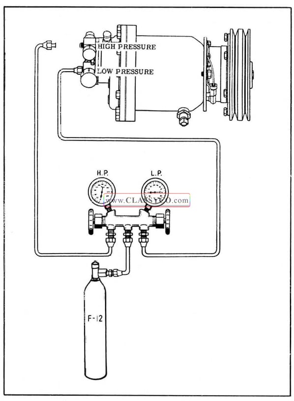
1957 Oldsmobile Evacuating the System (2)
- Remove cap from compressor high pressure gauge outlet, close high pressure gauge valve, and open low pressure gauge valve.
- Start engine and allow to run at slow idle. Move temperature control lever fully to the right. Position a container to receive any oil discharged from the high pressure gauge out let so that an equivalent amount of new oil can be added.
- Allow engine to run until 28″ of vacuum has been maintained for 5 minutes.
- While engine is running, install cap on com pressor high pressure gauge outlet and stop engine. Observe if 28″ vacuum will hold for 3 minutes.
NOTE: If vacuum does not hold, charge system with drum pressure and check for leaks.
- Open valve on Freon drum and allow com pressor to come up to drum pressure, then close valve.
- Purge the compressor again through the high pressure gauge outlet, then remove the cap from the gauge outlet and start the engine.
Allow to run at idle until 28″ of vacuum has been maintained for 5 minutes, then install cap on compressor high pressure gauge outlet and stop the engine.
- Open valve on Freon drum to charge compressor, then momentarily crack open the compressor high pressure gauge outlet cap to purge the air remaining in the high pressure side of the compressor.
- Remove the compressor high pressure hand shut- off valve cap, then turn valve fully counter-clockwise, and remove the cap from the high pressure gauge outlet.
- Crack open compressor high pressure hand shut-off valve to allow Freon to purge slowly from gauge outlet; then crack open high pressure gauge hose and connect hose to gauge outlet and tighten.
- Close valves on Freon drum and high pressure gauge.
- Turn compressor high pressure hand shut off valve two turns clockwise. Turn compressor low pressure hand shut-off valve fully counter-clockwise, then two turns clock wise.
- Check the system as outlined under ADDING FREON-PARTIAL CHARGE. If it is necessary to add Freon, omit steps 1 through 7 of the procedure for adding Freon, since the gauge set on Freon drum is already connected.
MALFUNCTIONING COMPRESSOR
A new compressor does not have the clutch actuating coil parts, the pulley clutch parts, or the hand shut-off valve assembly. A service shipping plate is bolted over two “O” rings to seal the valve port openings. The two “O” rings under the ship ping plate should be transferred to the old assembly and two new “O” rings used when installing the compressor on the car. A new compressor is charged with nine ounces of Frigidaire 525 Viscosity Oil, and a mixture of Freon-12 and nitrogen under approximately 5 p.s.i. pressure. Envelopes attached to the compressor contain enough shims to insure a sufficient number of shims for the compressor clutch adjustments. The old com pressor, with the shipping plate attached, should be packed in the returnable crate and shipped to: Frigidaire Division, Servicing Receiving-Plant No. 5, Moraine, Ohio.
Removal
- Remove protective caps from compressor high and low pressure hand shut-off valves.
- Turn both compressor hand shut-off valves two turns clockwise to open the compressor gauge outlets.
- Crack open compressor high pressure gauge outlet cap and allow Freon to purge from system until “hiss” is no longer heard; then turn both hand shut-off valves fully clockwise.
- Turn ignition switch to accessory position and temperature control fully to the right to energize clutch coil. Use a jumper wire to short out evaporator switch. Remove the lock, nut special washer, and felt washer from the hub of the pulley.
- Turn the ignition switch off and disconnect both wires at the clutch coil.
- Remove the belts from the compressor pulley.
- Remove the bolt holding the hand shut-off valve assembly to the compressor, then re move the assembly from the compressor.
- Remove the compressor-to-support bolts, then remove the compressor assembly.
- Remove the pulley, clutch, and coil. (Refer to PULLEY AND CLUTCH REMOVAL AND COIL REMOVAL)
Installation
- Position the new compressor on the support plates, then install and tighten the compressor to-support plate bolts to 15 ft. lbs. torque.
- Remove the protective covering from the shaft of the new compressor.
- Install coil, clutch, and pulley. (Refer to COIL INSTALLATION, AND CLUTCH AND PULLEY INSTALLATION.
- Connect coil wire.
- Turn ignition switch to accessory position and temperature control fully to the right to energize clutch coil. Connect a jumper wire be tween positive terminal and ground to short out evaporator switch.
- Check clearance between clutch plate and coil housing. If clearance is not between.025″ and.035″, it will be necessary to remove pulley and add or subtract shims. (Shim thickness.010″,.015″,.020″,.025″)
- Remove the shipping plate from the rear of the compressor and the two “O” rings from the valve port openings, and install two new “O” rings.
- Install the hand shut-off valve assembly on the compressor, then install the mounting bolt and tighten to 15 ft. lbs. torque.
- Install belts and adjust tension using Tool 33-70.
- Install a charging line to the compressor high pressure gauge outlet and to a drum of Freon- 12.
- Disconnect the liquid line from the dehydrator filter-receiver assembly on the inlet side, and cap the dehydrator-filter-receiver immediately.
- Turn the high pressure hand shut-off valve fully counter-clockwise, then turn it back two turns clockwise.
- Open the Freon drum valve and turn the drum upside down to allow liquid Freon to flush through the condenser and out the line. Use approximately 2 lbs. of Freon for this operation.
- Close the drum valve and connect the dehydrator-filter-receiver assembly.
- Remove the expansion valve screen and clean or replace as necessary.
- Remove the charging line from the compressor high pressure gauge outlet, install the gauge set, and evacuate the entire system as outlined under EVACUATING THE SYSTEM.
- Recharge the system as outlined under CHARGING THE SYSTEM WITH FREON – COMPLETE CHARGE.
ADDING FREON-PARTIAL CHARGE
The proper charge of Freon to insure a clear sight glass under operating conditions at various ambient temperatures is 4-7/8 lbs. Since less than 4-7/8 lbs. will result in a clear sight glass under some load conditions, it is necessary to consider load effects when checking and adding Freon to the system. The load can be varied by changing the blower speed as listed in the following chart. Be sure to operate the system for at least 5 minutes before checking sight glass.
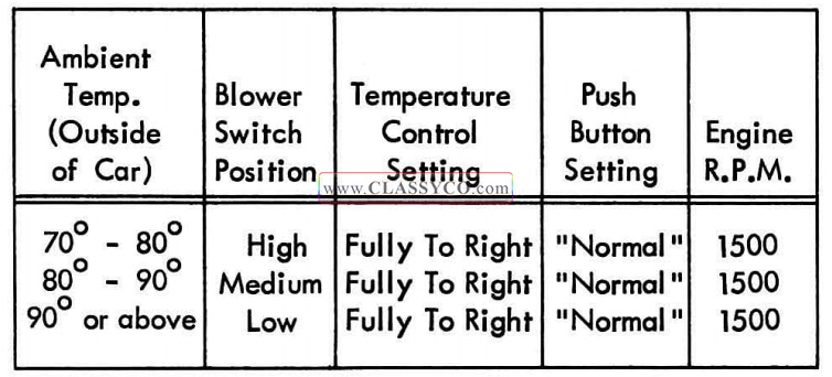
1957 Oldsmobile Adding Freon-Partial Charge Chart
If the system is low on Freon, proceed as follows:
- Turn off the ignition switch.
- Remove both compressor hand shut-off valve protective caps and make sure both valves are turned fully counter-clockwise.
- Remove both compressor gauge outlet fitting caps and install the gauge hoses on the fittings. (See Fig. 14-34)
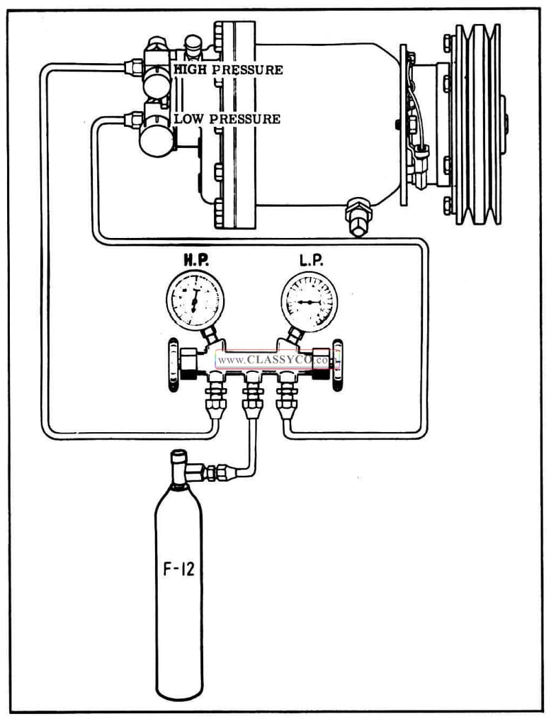
1957 Oldsmobile Adding Freon (Partial Charge)
- Make sure both gauge valves are closed, then turn both compressor hand shut-off valves two turns clockwise.
- Crack open both gauge valves to purge the gauge hoses through the center hose, and crack open the valve on the Freon drum or the “Fits All” Valve on a 15 oz. Freon can. While Freon is escaping from the center hose of the gauge set and the valve fitting on the Freon container, connect the center hose to the Freon container.
- Close the Freon container valve and both gauge valves.
- Start the engine and set at 1500 R.P.M. Make sure the temperature control lever is fully to the right, the “NORMAL” button is engaged, and the blower switch is set according to the preceding chart.
- Open valve on Freon container and the low pressure gauge valve to allow Freon to enter the system. When sight glass clears, close Freon container valve.
- Wait two minutes, then check the sight glass.
If vapor is still visible, open the Freon container valve and again allow Freon to enter the system. Add 1/4 lb. of Freon after sight glass clears.
- Shut off engine, turn both compressor hand shut-off valves fully counter-clockwise, remove gauge set, and install all protective caps.
CHECKING OIL LEVEL
If a refrigerant leak is found which indicates some loss of oil by the presence of oil around the leak, or if it is necessary to determine whether or not the compressor has a sufficient amount of oil, the following procedure should be used:
- Start engine and operate at 1500 R.P.M. with temperature control lever fully to the right and “NORMAL” button engaged for 5 minutes, then stop the engine.
- Slowly open the oil test valve on the compressor and allow the first surge of oil and Freon to escape against a clean cloth. The Freon will evaporate, while the oil will saturate the cloth.
NOTE: The first surge of oil may be only the amount of oil standing in the fitting. The valve should be held in the open position just long enough to be certain the oil level is at least to the top of the fitting.
- If oil continues to escape with the Freon vapor, the oil level in the compressor is satisfactory.
- If oil does not continue to escape from the test valve, the oil is below the minimum level.
ADDING OIL (Fig. 14-35)
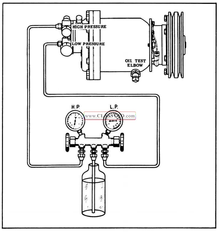
1957 Oldsmobile Adding Oil
- Remove protective caps from compressor high and low pressure hand shut-off valves and make sure valves are turned fully counter clockwise.
- Remove plug from high pressure gauge outlet and connect high pressure gauge hose to com pressor high pressure fitting.
- Install plug in center hose on gauge set.
- Turn compressor high pressure hand shut-off valve two turns clockwise and replace protective cap.
- Crack open the high pressure valve on the gauge manifold.
- Crack open the low pressure valve on the gauge manifold to purge air from gauge set. While vapor is still escaping from the low pressure gauge line, connect to low pressure fitting on the compressor hand shut-off valve.
- Close the high and low pressure valves on the gauge set.
- Turn the compressor low pressure hand shutoff valve fully clockwise.
- Remove center hose on gauge set and install oil charging line.
NOTE: Make certain oil line is clean. (Use a 1/4″ x 10″ copper tube with fitting to connect to center connection on gauge set.)
- Crack open the high pressure valve on the gauge set to purge air from the oil charging line.
- While vapor is still escaping from the oil charging line, uncap the oil bottle (Frigidaire 525 Viscosity) and insert the oil line to the bottom of the oil bottle and allow vapor to slowly bubble through the oil.
- Close high pressure valve on gauge set. Allow time for escaped vapor to dissipate. Leak test all connections that were made during repair.
- Position the gauge set and oil charging line, while still inserted to the bottom of the oil bottle so that it will not be disturbed during the following procedure.
- Move temperature control lever to extreme right position, engage “NORMAL” button, and start engine and allow to run at slow idle until approximately 10″ vacuum is obtained.
- Stop the engine and observe the low pressure gauge to see if the vacuum will hold. There should not be any fast change of gauge reading.
- Open the low pressure valve on the gauge set and allow 2 ounces of oil to be drawn from the bottle.
- Close the low pressure valve on the gauge set. Remove the oil charging line from the bottle and replace cap on bottle. Remove the oil charging line from the gauge set and install a cap on the center connection.
- Open the high pressure valve on the gauge set.
- Open the low pressure valve on the gauge set slowly to allow the high side pressure to force the oil remaining in the gauge set and low pressure gauge line into the compressor.
- Close high and low pressure valves on the gauge set and then turn compressor low pressure valve fully counter-clockwise and replace protective cap.
- Start engine and operate at 1500 R.P.M. with temperature control lever fully to the right and “NORMAL” button engaged for 5 minutes, then stop engine.
- Again open oil test valve and allow first surge of oil to escape against a clean cloth. If oil continues to escape the oil level is satisfactory. If oil does not come out after first surge, add another 2 ounces at a time, following previous procedure, until test indicates a sufficient amount has been added.
- Remove end cap from high pressure hand shut-off valve on compressor and turn valve fully counter-clockwise and replace end cap.
- Remove gauge lines and replace caps on gauge lines and on compressor valves.
CHECKING AND ADDING OIL AFTER MAJOR LOSS
The compressor was originally charged with 9 ounces of Frigidaire 525 Viscosity Oil. During normal operation, because of an affinity of Freon-
12 for oil, a certain amount of oil will circulate throughout the system along with the liquid and vapor. To determine if the compressor has sufficient oil, an oil test valve has been placed on the underside of the compressor body. If any major loss of oil has occurred, such as a severe com pressor seal leak, line breakage, damaged con denser, etc., proceed as follows after making the necessary repairs.
- Remove belts and coil electrical lead (black wire).
- Remove protective caps from compressor hand shut-off valves and turn valves fully clockwise. Remove low and high pressure hand shut-off valves from compressor by removing center bolt.
- Remove compressor-to-support mounting bolts.
- Transfer compressor to bench and remove oil test valve body.
- Allow all of the oil to drain from the compressor into a clean container; this is to determine the amount and condition of oil.
NOTE: If the examination of the oil shows any foreign material; sludge, water, etc., flush the system as outlined under INSTALLING A NEW COMPRESSOR.
- If the condition of the oil indicates that the compressor is free of any contamination, position the compressor so that the oil test valve flange is on the top side and pour from a graduated bottle, 9 ounces of NEW Frigidaire 525 Viscosity Oil into the compressor.
- Replace the oil test valve body. Use Frigidaire Sealer on plug threads.
- Install compressor on the engine and connect electrical lead to coil.
- Using new “O” rings, install compressor hand shut-off valves; then torque bolt to 15 ft. lbs.
- Install belts and adjust tension using Tool 33-70.
- Evacuate the system to remove air and moisture; then charge the system with Freon.
DIAGNOSIS AND SPECIFICATIONS
AIR CONDITIONING ROAD TEST
This test does not serve as a basis for diagnosis, but only as a guide to determine if the discharge air temperature is standard. If the discharge air temperature is not standard, make the performance test to locate the cause of the malfunction.
Drive the car at 20 m.p.h. with the temperature control lever fully to the right, “NORMAL” push button engaged, and a thermometer in the left air discharge nozzle. Make sure the windows and doors are tightly closed, since this can affect the velocity and the temperature of the discharge air. After taking the temperature reading, perform this test while traveling in the opposite direction to cancel any wind effect. Also, the relative humidity must be determined for this test since it will have an effect on the discharge air temperature.
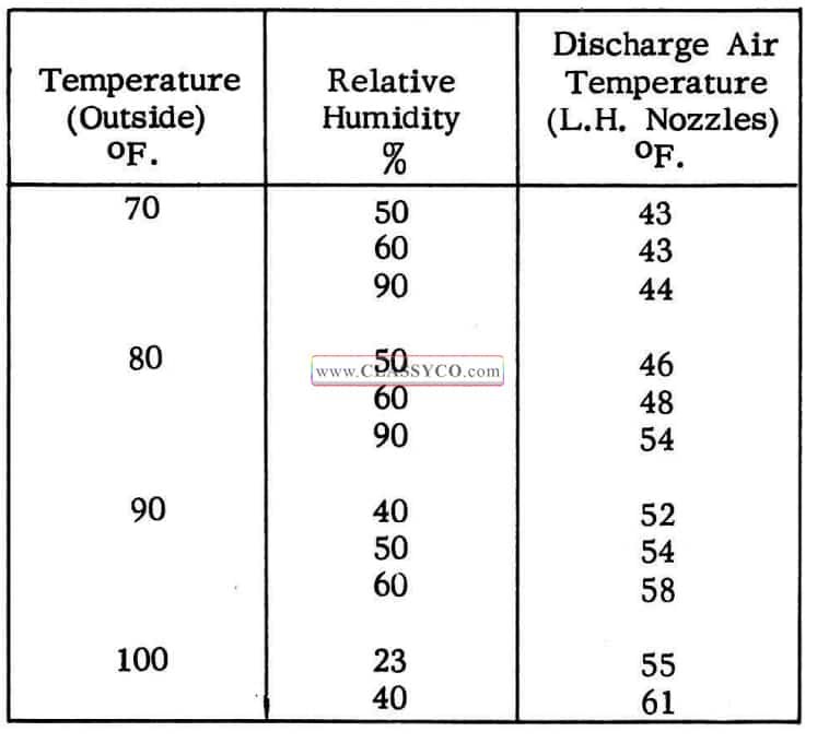
1957 Oldsmobile Air Conditioning Table
PERFORMANCE TEST
The Performance Test should be made with the car doors and windows closed, the temperature control lever fully to the right, “NORMAL” button engaged, fan speed switch on “HI”, an auxiliary fan in front of the radiator, and the car hood down as far as possible. Since the gauge hoses prevent the hood from being completely closed, cover the complete hood-to-cowl opening to prevent engine heat from entering the evaporator.
- Connect low pressure gauge with adapter to gauge connection in low pressure line near evaporator; then momentarily open the low pressure gauge valve to purge the gauge hose.
- Remove the compressor high pressure gauge outlet cap and install the high pressure gauge hose.
- Make sure high pressure gauge valve is closed; then turn the compressor high pressure hand shut-off valve two turns clockwise. Momentarily open high pressure gauge valve to purge the gauge hose.
- In Neutral, adjust engine speed to maintain 34 p.s.i. at the Schrader valve until stabilization is achieved.
- After temperature and humidity have been determined, compare test results with the Performance Charts.
- To obtain low pressure reading at compressor proceed as follows:
a. Connect tachometer and record engine R.P.M. with low pressure gauge still reading at 34 p.s.i. as outlined above.
b. Disconnect low pressure gauge at connection near evaporator.
c. Remove the compressor low pressure gauge outlet cap and install the low pressure gauge hose. (See Fig. 14-36)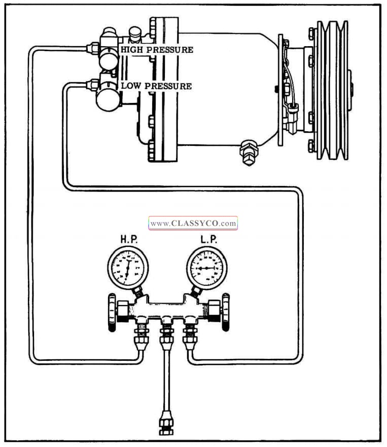
1957 Oldsmobile Gauge Connections for Pressure Test
d. Make sure the low pressure gauge valve is closed. Then turn the compressor low pressure hand shut-off valve two turns clockwise. Momentarily open low pressure gauge valve to purge the gauge hose.
e. Check tachometer to make sure engine R.P.M. has not changed. Then compare readings with Performance Chart.
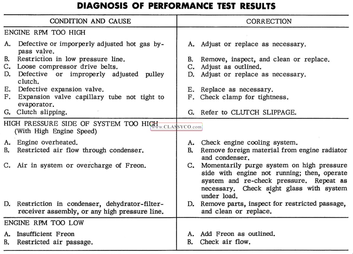
1957 Oldsmobile Air Conditioning Diagnosis of Performance Test Results
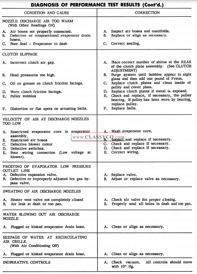
1957 Oldsmobile Air Conditioning Diagnosis of Performance Test Results 2
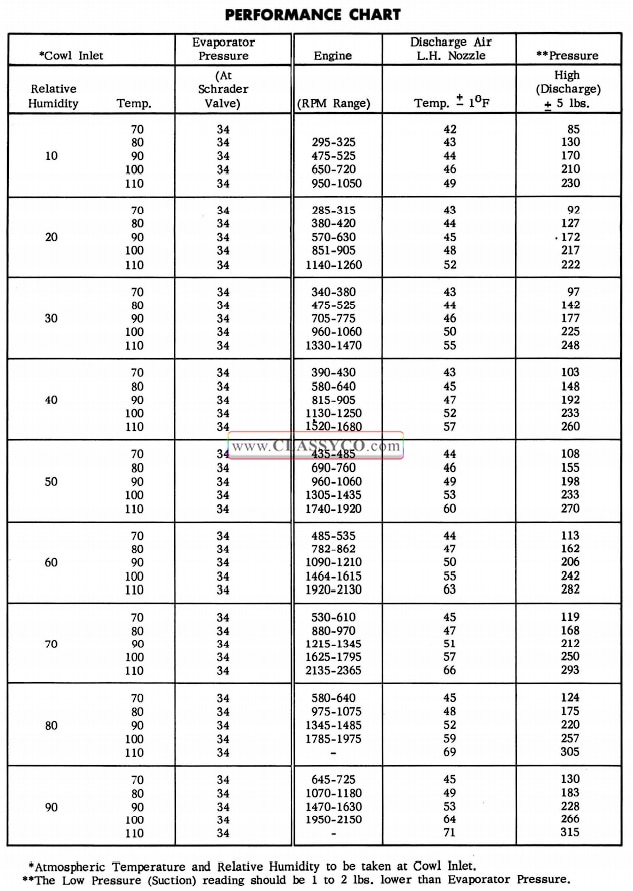
1957 Oldsmobile Performance Chart
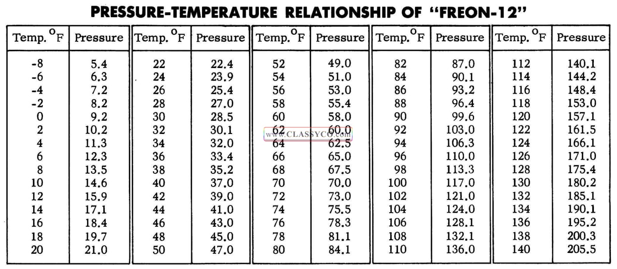
1957 Oldsmobile Pressure-Temperature Relationship of Freon-12
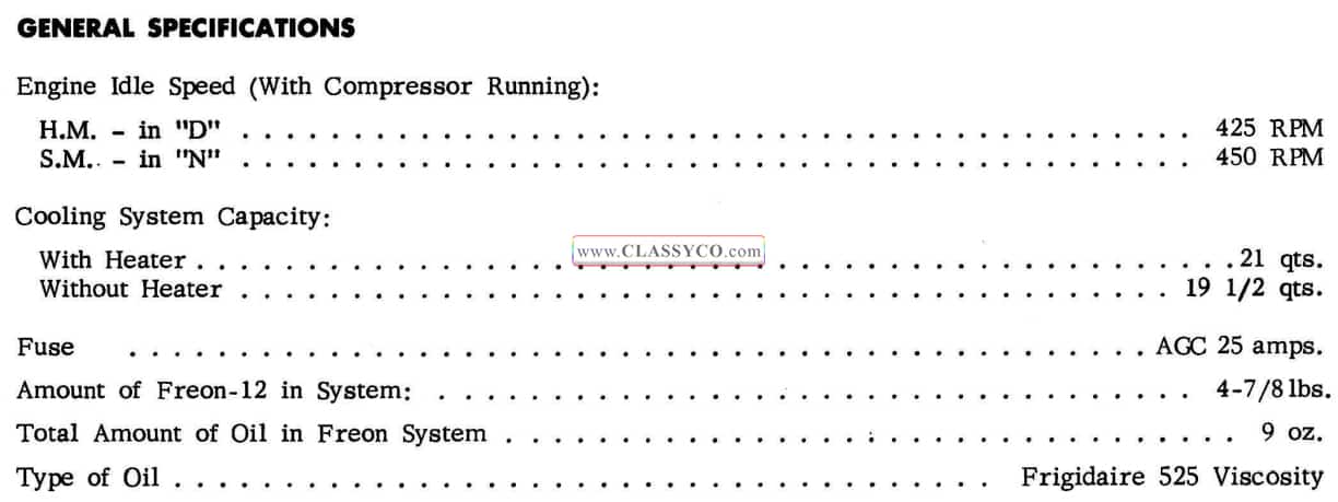
1957 Oldsmobile Air Conditioning General Specifications

1957 Oldsmobile Air Conditioning Torque Specifications

1957 Oldsmobile Air Conditioning Chassis Parts
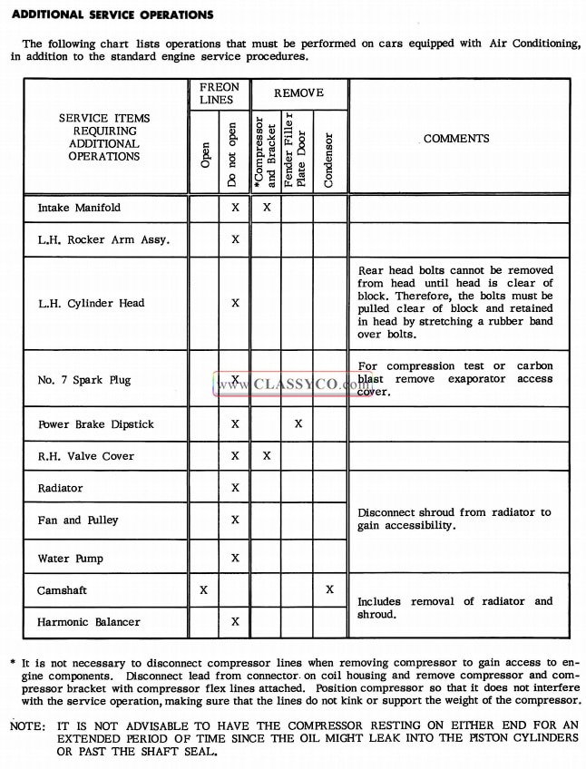
1957 Oldsmobile Additional Service Operations
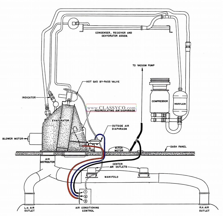
1957 Oldsmobile Schematic Diagram – Air Conditioning Only
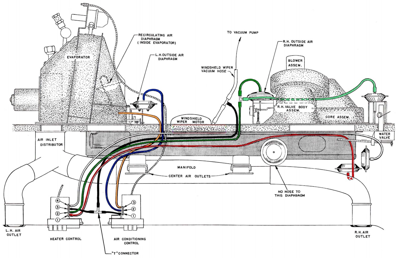
1957 Oldsmobile Schematic Diagram – Air Conditioning with Heater
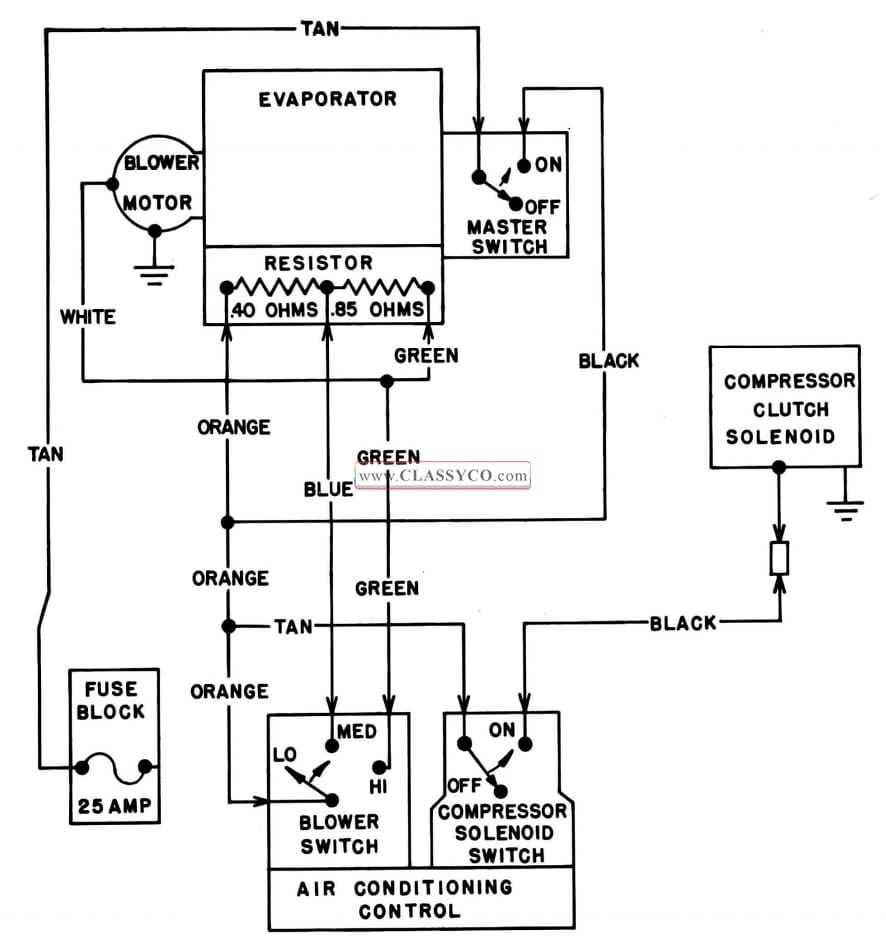
1957 Oldsmobile Wiring Diagram (2)

1957 Oldsmobile 98 Holiday Sedan (DHS)