ENGINE TUNE-UP
TUNE-UP PROCEDURE
- CLEAN BATTERY AND TEST SPECIFIC GRAVITY.
Clean battery as outlined in the Electrical Section. A warm battery reading below 1.215 should be recharged before tune-up is at tempted. If there is a variation of more than .025 between cells, a load test of the battery should be made. If battery is low, cause should be located and corrected.
- TIGHTEN ALL BATTERY, STARTER, GENERATOR, VOLTAGE REGULATOR, IGNITION SWITCH, AND COIL PRIMARY CONNECTIONS.
Loose connections cause high resistance and low voltage.
- CLEAN FUEL FILTER BOWL AND FILTER AND CARBURETOR INLET SCREENS.
No attempt should be made to clean gasket or filter. Always install a new bowl gasket. If water is present in fuel bowl, the fuel lines and tank should be cleaned. On cars equipped with the double-pulsating pump, the filter is located at the inlet side of the carburetor.
- TIGHTEN ALL FUEL, VACUUM, CHOKE, AND POWER BRAKE CONNECTIONS ON THE CARBURETOR, FUEL PUMP, AND DISTRIBUTOR.
As in the case of manifold gaskets, air leaks cause lean mixture and poor idle performance. A leak in the gas line between the gas tank and fuel pump will cause a high speed miss and/or failure to start; whereas, a leak between the fuel pump and carburetor will create a fire hazard.
- TORQUE ALL INTAKE MANIFOLD BOLTS AND TIGHTEN CARBURETOR ATTACHING NUTS.
Intake manifold bolt torque 25-30 ft. lbs. Air leaks at intake manifold cause rough idle and poor low speed performance due to lean mixture. If leak is suspected, test by squirting gasoline around intake manifold at cylinder heads, then observe combustion analyzer for richening of mixture.
NOTE: Remove choke heat pipe while making this test to prevent gasoline from entering through the heat pipe, which would richen the mixture. BE CAUTIOUS OF FIRE.
Torque exhaust manifolds and tighten exhaust system connections.
Exhaust manifold torque 22-26 ft. lbs. Exhaust leaks are not only annoying, they are hazardous. A good tune-up eliminates this hazard and the possibility of early gasket failure.
- CHECK CHOKE FOR PROPER SETTING, TIGHTEN COVER ATTACHING SCREWS, CHECK FOR FREENESS OF CHOKE VALVE AND SHAFT. TIGHTEN HEAT TUBE FITTING TO CHOKE HOUSING.
The automatic choke is controlled by heat and vacuum. The thermostatic spring should close the choke valve (engine off) at room temperature (75°F.) with choke set at index. When engine is started, vacuum tends to open the choke and also draws warm air to the thermo static spring through the manifold heat tube. Malfunctioning of the choke could be caused by a split or improperly assembled heat tube in the intake manifold or by a defective choke cover gasket.
A choke modifier is included on the 1957 carburetor to prevent “loading up” when the engine is warming up. When the throttle is opened considerably, such as in climbing a hill, the choke modifier will lean the mixture by opening the choke valve. The modifier is at its leanest point when the throttle is haIf open. (See ENGINE SECTION for adjustment)
- SERVICE THE AIR CLEANER.
Service the air cleaner in accordance with instructions outlined in the Lubrication Section. Remember, this unit not only protects the engine from harmful abrasives, it also can be responsible for rich mixture when it is restricted with dirt or too full of oil.
- CLEAN SPARK PLUGS, FILE END OF CENTER ELECTRODE FLAT – SET GAP AT.030″.
Before cleaning spark plugs, inspect the deposits on the electrodes. These deposits can indicate unfavorable conditions in the engine as follows:
a. Wet, black deposits indicate oil pumping.Inspect the drain-back hole in the rear of the cylinder head. If this hole is plugged, or if the valve stem oil deflector is defective, it is possible for oil to enter the combustion chambers. If neither of these conditions is present, these wet, black deposits indicate the need for engine repairs.
b. Soft, fluffy, black deposits indicate an excessively rich fuel mixture. Check the fuel mixture, automatic choke, and the owner’s driving habits. Excessive idling or low speed driving will cause the same deposits.
c. Red, brown, yellow, or white coatings are caused by lead deposits, indicating improper ignition of fuel.
The spark plug must be clean and properly adjusted to fire the fuel mixture. Sand blasting alone does not completely service the plug. In addition to blasting, the end of the center electrode must be filed flat. Always be sure to properly gap new or used plugs at.030″ using a round wire gauge.
NOTE: Do not file electrodes on new plugs.
- INSTALL SPARK PLUGS TO 25 FT. LBS. TORQUE USING NEW GASKETS.
Loose spark plugs mean loss of compression. Installing plugs too tight will damage plugs or threads. In tightening plugs, be sure that the top end of the socket wrench is sup ported to avoid cocking the socket against insulator, as this may crack the plug. Always remove dirt, paint, and other foreign material from insulator. Be sure sleeves are in good condition and installed to cover the cable terminals and spark plug insulators.
- ADJUST ALL BELTS USING TOOL 33-70 AS SHOWN IN FIGURE 9-1. REPLACE FRAYED, BADLY WORN, OR OIL-SOAKED BELTS.
Loose fan and generator belt means improper engine operating temperature and an improperly charged battery. Engine temperatures and battery voltage affect performance and economy. Tight belts may damage water pump or generator bearings and cause rapid belt wear.
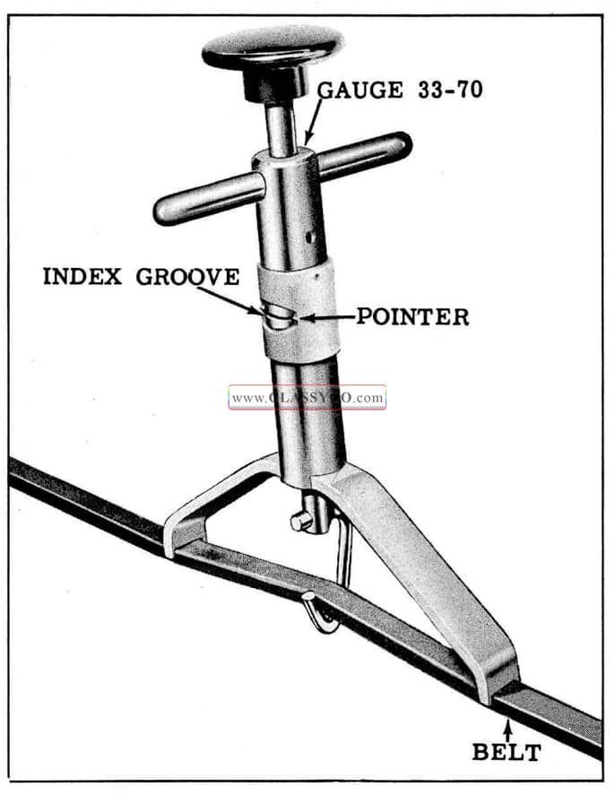
1957 Oldsmobile Checking Belt Tension
- CHECK MANIFOLD HEAT CONTROL VALVE FOR FREENESS AND PROPER OPERATION.
Proper operation of the heat valve is essential to good performance and economy. A heat valve stuck in the open position means poor warm-up and rich carburetion. A valve stuck closed means poor high speed operation. Make sure that the thermostatic spring is installed properly. (See Fig. 9-2) The thermo static spring is designed to close the valve as it cools. As the spring warms and the engine speed increases, the counterweight and exhaust gas pressure open the valve. Be sure the valve is free and operates in this manner. If the shaft is tight it may be freed-up by rotating the counterweight and applying a graphite base lubricant to the bearing surfaces.
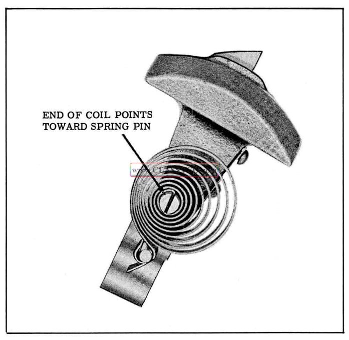
1957 Oldsmobile Thermostatic Spring Position
CAUTION: Never oil the bearing surfaces as carbon may form and “freeze” the counter weight shaft.
The following is a quick test: With cool exhaust manifold, start engine and flash the throttle quickly. Heat valve should open and return to closed position. Valve opens when weight rotates downward. If valve does not open in the above check, and the counter weight shaft is free, it indicates that either the valve is loose on the shaft or the shaft is broken; in either case the heat control valve should be replaced. A rattling or “buzzing” noise audible during the above test, indicates that the shaft bushings are worn, requiring replacement of the heat valve.
- BE SURE CONDENSER LEAD WIRE AND BREAKER PLATE GROUND WIRE IN DISTRIBUTOR ARE PROPERLY TIGHTENED.
- FILE DISTRIBUTOR POINTS. BE SURE TO REMOVE ANY METAL BUILD-UP ON EITHER POINT. REPLACE EXCESSIVELY BURNED OR PITIED POINTS.
A slight build-up on the stationary point is normal, but if points are prematurely burned or pitted check the following units:
a. Voltage regulator adjustment.
b. Dwell angle.
c. Condenser (loose lead, loose mounting, faulty condenser).
An out-of-balance condition in the ignition system can cause pitting. If the stationary point has excessive build-up, the condenser has too much capacity. If the build-up is on the movable point, a condenser with higher capacity should be installed.
- START ENGINE, BRING UP TO NORMAL OPERATING TEMPERATURE AND CHECK CAM DWELL.
This is done in preparation for setting the ignition timing. The cam dwell can be checked and/or adjusted as the engine is being warmed up.
CAM DWELL: 28° to 32°
If the cam dwell is outside of the above limits, adjust to 30° as outlined in the Electrical Section.
Flash throttle and observe dwell indicator for variance, allowable variance ‘l’. If dwell indicator reading is erratic, primary wiring and distributor should be checked. If dwell is erratic and other conditions are O.K., check dwell meter.
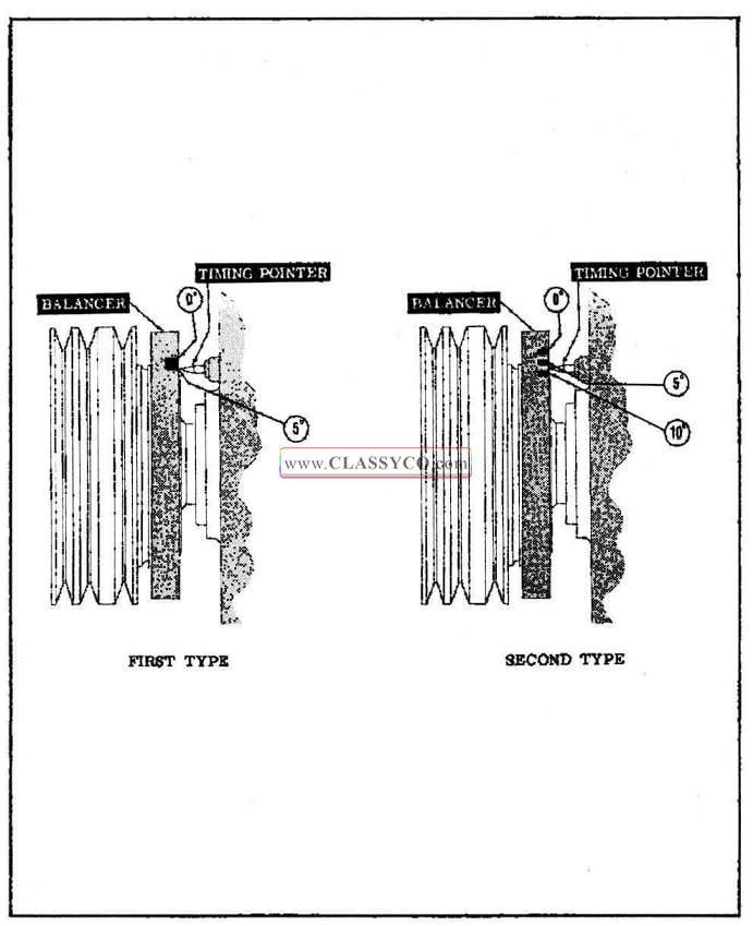
- ADJUST IGNITION TIMING. Figure 9-3
The timing marks are located on the rim of the crankshaft balancer. On the first 15,000 cars produced, the leading edge of the notch is before top dead center. The trailing edge of the notch is top dead center. Midway between is 2 ½° before top dead center. The second type balancer has three saw slots, representing top dead center, 5° before top dead center, and HF before top dead center. The correct method of setting timing is as follows:
a. Disconnect distributor vacuum advance line at the carburetor and close fitting with a piece of tape.
b. Set engine to run at 850 R.P.M.
c. Set timing at 5° before top dead center. This is normal setting.
1957 Oldsmobile Setting Ignition Timing
NOTE: If a tuned engine detonates with this setting, the cause is low octane fuel or carbon build-up in the combustion chamber. If these factors are not corrected, the timing should be set at 2 l/20 before top dead center at 850 R.P.M. In some cases where fuel octane is good or the engine is clean or the car is operated at high altitudes, the timing can be set at 7 1/2° before top dead center at 850 R.P.M. without detonation and with some advantage in performance and economy.
d. Remove tape, connect distributor vacuum advance line, and reset slow idle.
16. MAKE MILLIAMP TEST AT SPARK PLUGS.
The milliamp test will indicate the presence of faulty ignition cables, cracked distributor cap, or burned rotor.
NOTE: When making a milliamp test, use the indicated reading values as furnished by the testing equipment manufacturers.
a. Connect tachometer, start engine, and set engine speed according to the directions on the test equipment.
b. Set meter knob to secondary efficiency position.
c. Ground positive lead.
d. Check each spark plug lead by connecting the positive lead of the meter directly to the cable. A variation of 5 graduations between plugs is allowable.
e. A low reading indicates high resistance in the circuit. If a low reading is encountered, disconnect the cable from the spark plug and check the reading again. If the reading increases, the spark plug is partially shorted.
f. A low reading with the cable disconnected from the spark plug indicates:
(1) Poor connection on either end of the cable.
(2) Burned or corroded connector inside the distributor cap.
(3) Damaged or broken cable.
Clean and inspect the distributor cap connection and the terminals on both ends. Check cable insulation for cracks, pinholes, or an oil-soaked condition. DO NOT attempt to shorten, rework, or repair cables.
NOTE: If the milliamp reading is still unsatisfactory, carefully check the distributor cap and rotor for leakage or cracks. Test the coil, condenser, and primary circuit, including starter solenoid connections, ignition switch and terminals, as well as the coil and distributor terminals.
g. A low reading on all cables indicate&:
(1) Burned or broken rotor.
(2) Faulty distributor cable.
(3) Weak coil.
(4) Cables not tight in distributor cap.
(5) Excessively burned rotor or distributor cap electrodes.
(6) Spring button not contacting carbon brush in distributor cap.
(7) Incorrect breaker point tension. (19-23 oz.)
- ADJUST CARBURETOR IDLE (AIR CLEANER REMOVED)
Engine must be at operating temperature and throttle return check holding tool in position. On cars equipped with air conditioning the compressor clutch must be engaged.
H.M.T. in “Dr” – 425 R.P.M.
S.M.T. in “Neutral” – 450 R.P.M.
After the idle R.P.M. is stabilized, turn in or out each idle adjusting needle screw until the smoothest possible idle is obtained. This normally is accompanied by a higher manifold vacuum reading and/or an increase of idle R.P.M. Then, turn out (rich) each needle 1/4 turn, at which time both the idle vacuum and R.P.M. will drop off slightly. This adjustment will prove to be correct for all normal idle requirements.
A final check of the foregoing adjustment can be made by slowly opening the throttle until approximately 1000 R.P.M. is reached and then allowing the throttle to snap closed rapidly. The engine should return to normal idle with no indication of rolling due to rich ness. If a slight rich roll is experienced, turn each idle needle in (lean) no more than 1/8 turn, which should provide the stable idle desired.
- ADJUST FAST IDLE TO SPECIFICATIONS WITH ENGINE WARM.
Correct fast idle adjustment prevents stalling when the engine is cold. High Step – 1400-1500 R.P.M.
ROAD TEST AND DIAGNOSIS
Road Test Car Thoroughly
Check the engine performance at HIGH SPEED, LOW SPEED and IDLE.
NOTE: AFTER ROAD TEST, INSPECT ENGINE FOR OIL AND WATER LEAKS.
There are numerous possible causes of trouble in the ignition system that can cause the engine to miss at High or Low speed, most of which have been covered in the tune-up procedure. Additional items to check are listed below:
A. Ignition System.
- Be sure the cable terminal fits tight on spark plug terminal.
- Reinspect spark plug for lead deposits on electrodes.
- Check spark plug for an insulator crack under plug body shell.
- Recheck milliamp output at spark plug cable terminal.
- Check all primary ignition wiring and connections
- Check distributor cap for cracks.
- Check ignition system resistance. (See ELECTRICAL SECTION)
- Check distributor mechanical advance mechanism for binding or stickiness.
B. Fuel System.
- Carburetor float level adjusted too LOW or too HIGH or leaky needle seat.
- Dirt and/or corrosion in carburetor fuel or air passages.
- Low capacity fuel pump. (See ENGINE SECTION)
- Punctured vacuum diaphragm in pump assembly. Careful examination of the carburetor and fuel system should reveal defects if present. Always be ACCURATE with the carburetor adjustments when overhauling a carburetor.
C. Valve System.
- Sticking valve due to carbon and/or varnish deposits.
- Broken or weak valve spring.
- Warped, cracked or burned valve.
- Valve not seating correctly.
- Faulty hydraulic valve lifter.
- Bent push rod, push rod worn excessively, or push rod seat worn in rocker arm.
- Incorrect valve timing.
To determine if the valves are at fault, a test should be made to determine the cylinder compression pressure. This is done in the same manner as when testing for worn pistons or rings. When checking cylinder compression, the throttle and choke should be open, all spark plugs removed, and the battery at or near full charge. The lowest reading cylinder should not be less than 80% of the highest, and no cylinder reading should be less than 100 pounds.
D. Miscellaneous Causes:
- Clogged muffler.
- Pre-ignition, due to sharp carbon deposit in the combustion chamber.
- Poor ground connection between engine and frame or body.
Engine Rough on Idle – May Miss on One Cylinder
An engine may perform at High speed and Low speed driving, but will idle rough or even miss on one or more cylinders; when permitted to idle a normal short period. This condition may be due to:
- Spark plug has incorrect specification number (heat range).
- Leak in intake manifold.
- Varnish or carbon deposits around carburetor throttle valves and body.
- Leak in floats causing flooding condition.
- Idle jets clogged.
- Worn or bent idle adjusting screw.
- Sticking, poorly seated, or burned engine valve.
Restricted movement of front engine mount due to being oil soaked, misaligned or insufficient clearance between inner and outer mount will cause the idle to feel rough. Engine Stalls on Idle.
An engine that idles slower than standard specifications will contribute to stalling. Check the following;
- Flooding of carburetor.
- Clogged climatic control passage in choke housing.
- Cracked heat tube in manifold. (Indicated by choke piston excessively carboned).
Engine Surges or Cuts Out.
At times a surge or cut out of the engine may be noticeable. This is usually noticeable at moderately fast driving when the accelerator is held in a steady position.
Surging or cutting out can be due to:
- Stopped up fuel line.
- Stopped up gas tank cover vent.
- Air leak at fuel pump filter bowl.
- Leak in fuel line between gas tank and fuel pump.
Poor Acceleration.
Performance (acceleration) is dependent on the proper amount of fuel to satisfy the engine’s demand when the throttle is opened rapidly. Also, the correct heat must be applied to the manifold.
Poor acceleration can be caused by:
- Incorrect setting of the accelerator pump.
- Worn throttle linkage or carburetor linkage.
- Manifold heat valve sticking.
- Clogged heat passage in climatic control housing.
- Heat tube in manifold cracked.
- Inoperative distributor advance.
The interval at which major service work is required on the carburetor, distributor, valve mechanism, etc., will vary with operating conditions. Prescribe this work only when a thorough diagnosis indicates the need.
For Instance:
Accumulation of carbon on· the combustion chambers· causes loss of power and performance and may result in detonation or “Spark Ping.”
The rate and type of carbon accumulation is dependent upon the fuels and engine oils used, operating conditions, and driver habits. However, when it is known that recommended fuels are being used and the engine detonates with correct spark setting, the owner should be sold a carbon removal job, as an engine tune-up alone will do little good, if any, to satisfy the owner. The carbon can be removed in a very short time with the Head-On Carbon Blaster and the owner will be gratified with the results.
1957 Oldsmobile 98 Convertible Coupe (DCR)