CHASSIS SHEET METAL
VENTILATION AND HEATING
CHASSIS SHEET METAL
GENERAL INFORMATION
The 1957 hood has studs on the under side which enter the hood support bracket of the hood hinge. (See Fig. 16-1) Thus, the hood panel can be removed without removing the hinge and spring assembly. The hinge and spring assembly is also removable from the cowl as a unit.
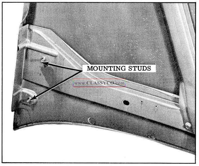
1957 Oldsmobile Hood Mounting Studs
The hood hinge is a gear -type, two-link hinge with an over-center spring, which provides hold open force and assistance in opening and closing the hood.
HOOD ALIGNMENT
The hood hinge adjustment provides lateral and vertical alignment of the rear edge of the hood. All hood hinge- to -cowl mounting bolt holes are enlarged to permit movement for adjustment.
- Loosen hinge bracket to cowl bracket bolt “A” on each side. (See Fig. 16-2) Lower hood.
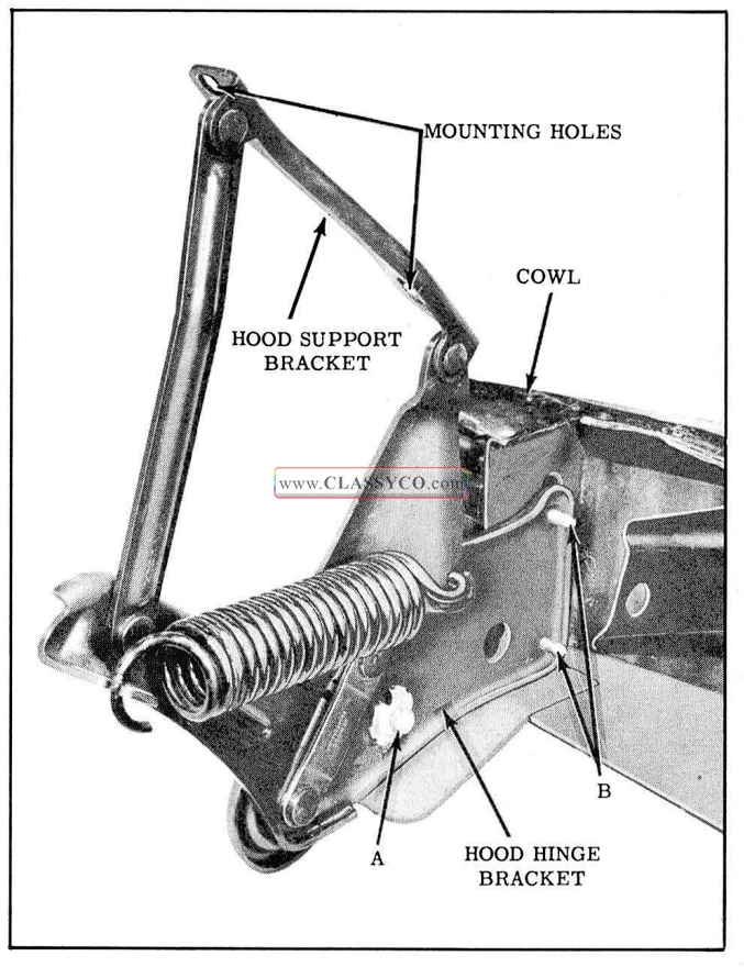
1957 Oldsmobile Hood Hinge Assembly
- Remove heater control diaphragm on R.H. side of car und er instrument panel to prevent damage to diaphragm.
- Loosen hinge bracket to cowl bolts, “B”, und er instrument panel on both sides. (See Fig. 16-2) Leave bolts snug enough to keep bracket from falling out of position.
- Shift hood into position to obtain clearances as shown in Fig. 16-3.
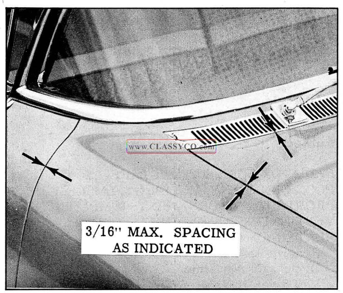
1957 Oldsmobile Sheet Metal Clearances
- Tighten hinge bracket to cowl bolts from inside of cowl, both sides.
- Raise hood and tighten hinge bracket to cowl bracket bolt, each side.
- Replace heater control diaphragm on R.H. side of car.
PILOT BOLT
After aligning the hood hinges, the hood pilot bolt and rubber bumpers should be adjusted. The pilot bolt, on we under side at the front of the hood, aligns the hood as it is lowered. Vertical adjustment can be made by loosening the pilot bolt lock nut and adjusting the threaded pilot bolt up or down. The distance between the lower edge of hood and top of primary upper bar should be approximately 1″. (See Fig. 16-4) Tighten lock nut after adjustment is completed. The rubber bumpers at each end of the fender tie bar must be adjusted for alignment of the corners of the hood with the fenders. The latch assembly, located at the center of the fender tie bar and tie bar support, has enlarged mounting bolt holes to permit movement for lateral hood alignment. The gap between the side of the hood and the front fender should be 1/8″ maximum. (See Fig. 16-4).
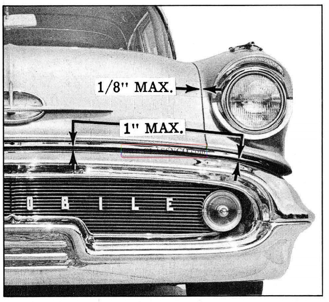
1957 Oldsmobile Hood Front Clearances
REMOVE AND INSTALL HOOD ASSEMBLY
NOTE: Place protective covering over cow1 and fender areas to prevent damage to paint and moldings when removing or replacing hood.
- Disconnect under-hood lamp wire.
- While supporting hood, remove two mounting stud nuts on each side of hood. (See Fig. 16-1)
- Remove hood panel.
To install, reverse above sequence of operations and check hood alignment.
NOTE: The mounting stud holes in the hood support bracket are slotted to provide a slight fore-and-aft adjustment.
HOOD HINGE SPRING
When removing the spring from the hood hinge, raise hood haIf way to expand spring and place Tool 6506 over the spring. (See Fig. 16-5) When installing a new spring, a suitable expander must be used to stretch the spring. Then Tool 6506 can be placed over the spring.
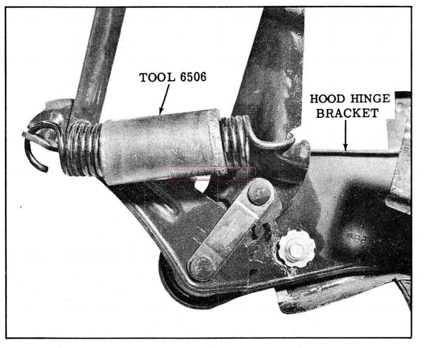
1957 Oldsmobile Hinge Spring Tool in Position
HOOD HINGE
When replacing a hood hinge assembly only, it is important to remove the spring BEFORE removing the assembly from the cowl, unless spring and hinge assembly are both to be replaced It is necessary to remove the diaphragm which partially closes the heater louvers to remove the right hand lower hood hinge bracket-to-cowl bolt. Mark the hood hinge outline on the cowl before removal to facilitate alignment when replacing. Auto body caulking compound should be placed around the hinge bracket-to-cowl bolt holes. Align hood after replacing hinge.
BUMPER ALIGNMENT
Vertical and horizontal alignment of the front bumper assembly is provided tor through the use of eccentric bolts attaching the secondary bar to the frame. (See Fig. 16-6)
To align the front bumper, the secondary bar to-frame attaching bolts should be loosened on both sides, and the eccentric bolts rotated to the desired position. Make sure that the clearance between fenders and bumper is even on both sides. Tighten all secondary bar to frame attaching bolts 50-60 ft. lbs.
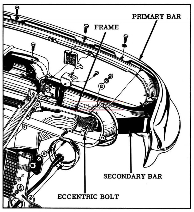
1957 Oldsmobile Front Bumper Alignment
FENDER (See Fig. 16-7 and 16-8 for Fender Attachment)
Before removing and replacing a fender, painted areas and moldings adjacent to the fender should be covered for protection against scratches. When replacing a fender, it is important that all anti-squeaks and seals be reinstalled. If the anti-squeaks and seals are damaged, they should be replaced.
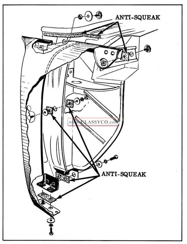
1957 Oldsmobile Fender Attachment
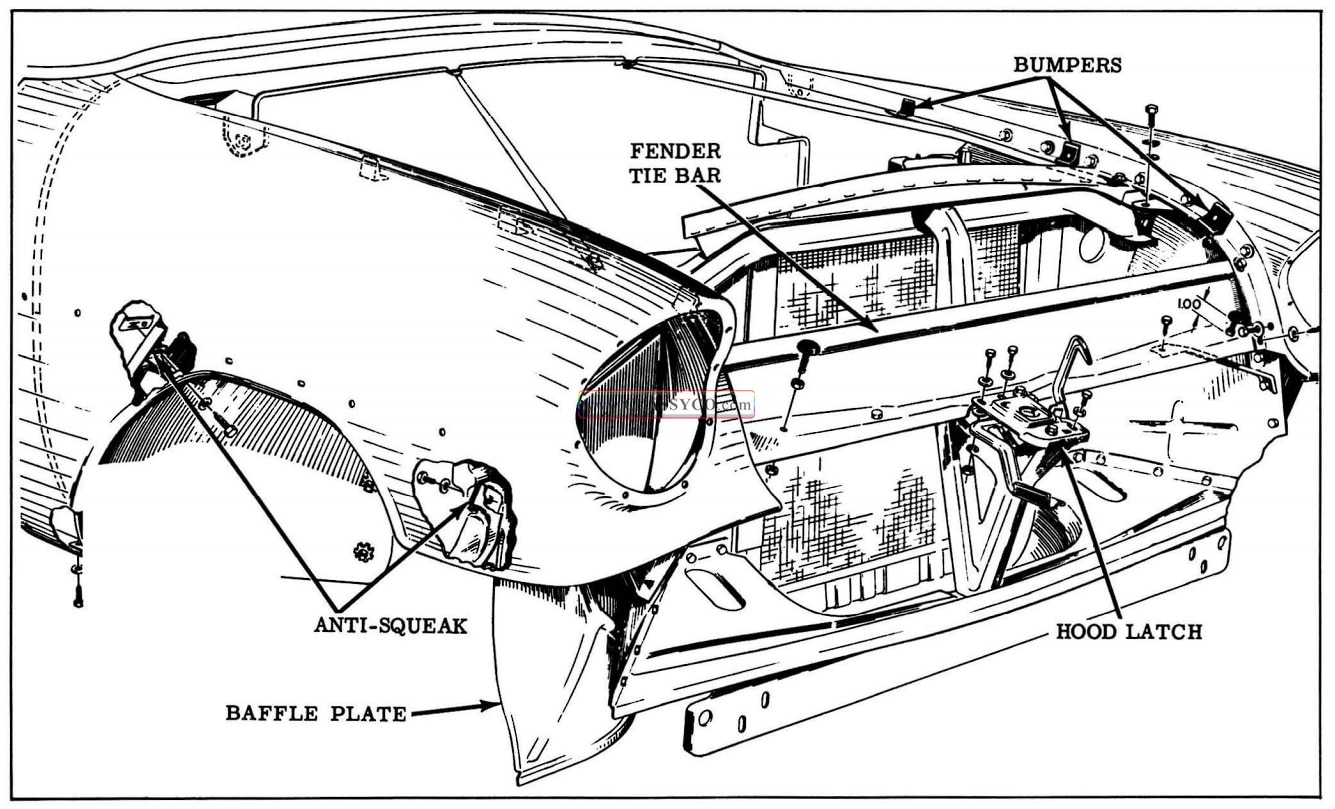
1957 Oldsmobile Fender Attachment and Tie-Bars
FENDER ALIGNMENT
The holes in the body and cowl are enlarged to permit adjustment. When making installation, fender should first be placed firmly into position, and before replacing any bolts, make sure the r ear end of the fender matches the contour of the door. This adjustment is made by use of shim washers on the stud at the rear center of the fender. (See Fig. 16-7) After this contour adjustment, install and tighten all fender bolts just enough to permit shifting as required. After fender is properly positioned, tighten all attaching screws and bolts.
FENDER FILLER PLATE AND BAFFLE (Fig. 16-9)
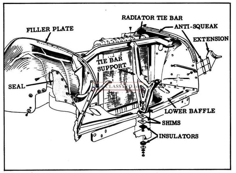
1957 Oldsmobile Filler Plate and Baffle Attachment
All necessary wiring and parts should be dis connected or removed before removing the filler plate. It is important that all seals and anti-squeaks be checked and replaced, if necessary, before installing.
NOTE: After the voltage regulator has been reinstalled, the generator must be polarized. (See ELECTRICAL Section)
The front fender baffles can be removed without removing any other parts. When removing a fender, the baffle plate, (See Fig. 16-8) unless damaged, should be left attached to the fender filler plate. If the baffle has been damaged and a new fender and baffle plate is to be installed, alignment of mounting holes is made easier by attaching the baffle to the filler plate first. After the fender has been installed, the baffle plate can be bolted to the fender.
RADIATOR
(See Cooling System)
RADIATOR CORE SUPPORT BAFFLES (Fig. 16-10)
The top, left, and right radiator baffles can be removed without removing any other sheet metal parts. After removing all attaching screws, the radiator side baffles may be removed by lifting them straight up. To remove the lower radiator baffle, the bumper assembly and fender tie bar support must be removed.
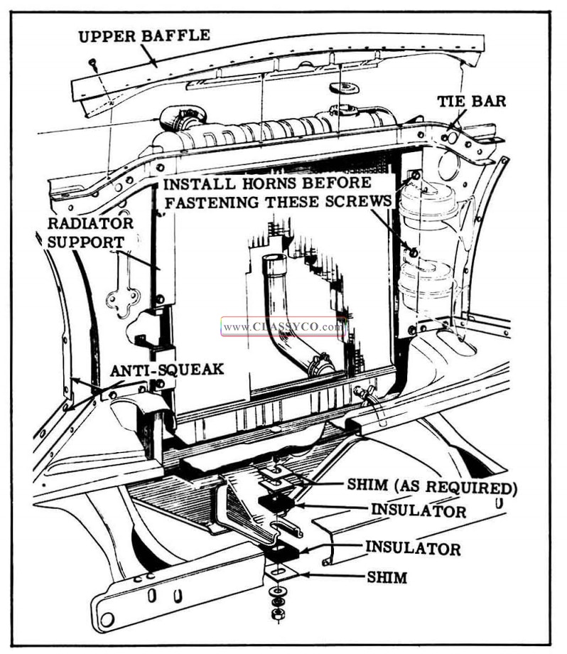
1957 Oldsmobile Core Support Baffles
HOOD ORNAMENT, MOULDING AND EMBLEM
Hood Ornament and Molding
The hood ornament is fastened to the hood by two self-tapping screws and a self-threading nut, all of which are accessible from the underside of the hood. Five self-threading nuts hold the molding to the hood.
When removing the ornament or molding, unscrew the self-threading nuts, taking care not to break the studs. New nuts should be installed by screwing them onto the studs with a suitable tool.
Hood Emblem
The hood emblem is fastened to the front of the hood by six stud bolts and lock nuts and two self threading nuts, all of which are accessible from the underside of the hood. The self-threading nuts should be removed as described under HOOD ORNAMENT AND MOLDING.
FRONT FENDER ORNAMENTS AND MOLDING
Ornaments
The front fender top ornament is fastened to the fender by two self-tapping screws and two self threading nuts. To remove the self-threading nuts, refer to HOOD ORNAMENT AND MOLDING. The front fender side ornament is attached by two push-on type nuts.
Front fender script letters are fastened by push-on type nuts as follows:
Fiesta 3
Super 88 4
Ninety Eight 3 (each word)
Molding
The front fender side molding is retained by seven sheet metal “Pal” nuts which thread onto “T” bolts in the molding retainers and 2 sheet metal pincer type fasteners.
To facilitate removal of moldings, script, or ornaments, disconnect the fender to gain access.
VENTILATING AND HEATING SYSTEM
VENTILATING AIR CONTROL
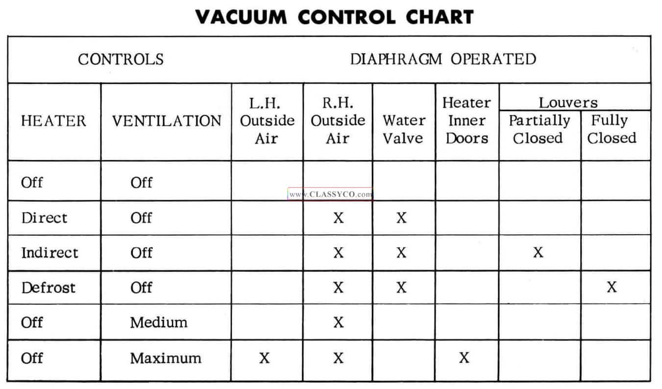
Outside air enters the ventilating and heating system through the cowl inlet at the base of the windshield. The flow of ventilating air is regulated by the air control located on the instrument panel at the right side of the steering column bracket. (See Fig. 16-11) The push buttons on the ventilation control panel regulate the left and right out side air valves and the inside doors in the heater when no heat is desired.
When the Medium button is pressed, the right hand outside air valve opens, closing the heater master switch and starting the blower. This provides outside air ventilation through the heater. The water valve remains closed. The louvers are held open by springs. When the Maximum button is pressed, the right and left hand outside air doors are open and the master switch is closed. In addition, the diaphragm on the top of the heater opens the two inside doors to permit maximum ventilation.
Cars without heaters are equipped with a push-pull control cable for left side ventilation.
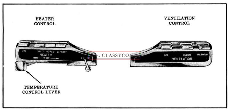
1957 Oldsmobile Heating and Ventilating Controls
HEATER AIR CONTROL
Outside air is brought into the driver’s compartment through the heater. The flow of air is regulated by the heater control push buttons located on the instrument panel at the left side of the steering column. (See Fig. 16-11) The push buttons on the heater control panel provide direct, indirect, and defroster air flow. A sliding lever under the push buttons adjusts the opening of the water valve. The blower motor switch is located at the right of the push buttons.
All air valves and the heater louvers are operated by springs and vacuum diaphragms which are controlled by the push buttons. Vacuum is obtained from a “Tee” connection in the windshield. wiper hose.
The outside air valves are closed by spring force and opened by the diaphragms. The louvers in the heater outlets are pivoted open by spring force and closed by two diaphragms. The louvers in each outlet are connected by mechanical linkage so that they open in opposite directions. One of the diaphragms closes the louvers partially; the other closes them fully. When the “Direct” button is pressed, the louvers open fully. The “Indirect” button closes the outlet halfway and directs the air along the sides of the car.
Two doors inside the heater have fixed openings which allow a predetermined amount of air to flow when either heater button or the ”Medium” ventilation button is pushed. They open completely only when the “Maximum” ventilation button is pushed. An auxiliary switch mounted on the right hand out side air valve housing prevents operation of the blower unless the heater, defroster, or ventilation is in operation. (See Fig. 16-12) When the air valve opens, the switch closes and the blower starts.
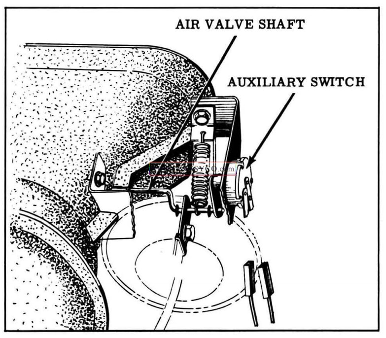
1957 Oldsmobile Auxiliary Switch
Remove and Install Controls
- Remove fan speed switch knob and sliding lever knob. (Heater only)
- On cars with air conditioning, remove the air manifold.
- Remove the 2 control assembly attaching nuts.
- Push the control unit through the instrument panel and lower.
- Remove water valve control cable, vacuum hoses, and switch wires.
- To install, reverse removal procedure.
Refer to schematic diagrams (Fig. 16-16 and 16-17) for proper installation of hoses.
Diaphragm Adjustments
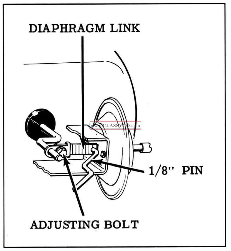
Adjustment of the air valves and diaphragm linkages is provided at the diaphragm.
- Pull out the diaphragm link and place a 1/8″ rod in the gauge hole in the link. (See Fig. 16-13)
- Loosen the adjusting bolt and pull the link away from the diaphragm sufficiently to rotate the air valve the maximum amount.
- Tighten the adjusting bolt and remove the 1/8″ rod.
1957 Oldsmobile Diaphragm Adjustment
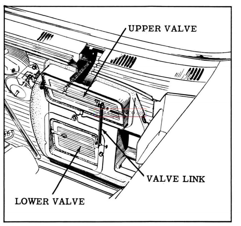
Left Side Upper and Lower Air Valves (Fig. 16-14)
The upper and lower air valves on the left side are connected by a link, and are operated by a single diaphragm.
The upper end of the left hand air valve link has four holes for adjustment. The proper hole is selected as follows:
- Hold upper air valve closed tightly.
- Place lower end of link on lower air valve operating crank.
- Pull up on connecting link to close lower air valve.
- Place nearest hole in the upper end of the link on to the upper air valve operating crank.
1957 Oldsmobile Left Hand Air Valve Adjustment
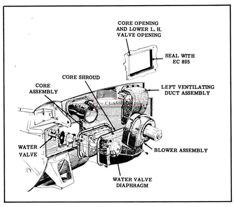
BLOWER AND DUCT ASSEMBLY (Fig. 16-15)
When replacing the duct assembly, scrape off old sealing compound to insure good seating, and place a 3/16″ bead of 3M Autobody sealer or equivalent sealing compound around entire duct assembly flange.
1957 Oldsmobile Blower Duct and Assembly
Remove and Install Blower Motor
The blow er motor may be removed for servicing or replacement without removing entire blower assembly as follows:
- Disconnect motor wire from connector on right side of duct assembly.
- Disconnect ground wire from duct assembly.
- Remove motor mounting flange plate-to-blow er assembly screws and remove motor. (See Fig. 16-15)
To replace, reverse sequence of operations.
Remove and Install Heater Core (Fig. 16-15)
- Disconnect blower motor wire from connector.
- Dra in radiator and disconnect hoses from heater core.
- Remove blower assembly.
- Remove air duct assembly.
- Remove core from duct assembly.
- Remove core shroud-to-core Phillips head screws, located on each side of shroud opening, and remove core from core shroud. To reach the screws on the side, it is necessary to push aside slightly the rubber molding on the core shroud. To replace, reverse sequence of operations.
Remove and Install Left Ventilating Duct Assembly (Fig. 16-15)
The assembly is removed by taking out the duct assembly flange-to-dash hex head screws. Before replacing, clean old sealing compound from dash to insure good seating; then place a 3/16″ bead of 3M Autobody sealer or equivalent around entire duct assembly flange.
If car is equipped with Autronic-Eye, all wiring leading to units mounted on left hand duct assembly must be disconnected. After reassembling duct assembly, be sure wiring terminals are connected at proper places.
1957 Oldsmobile Vacuum Control Chart
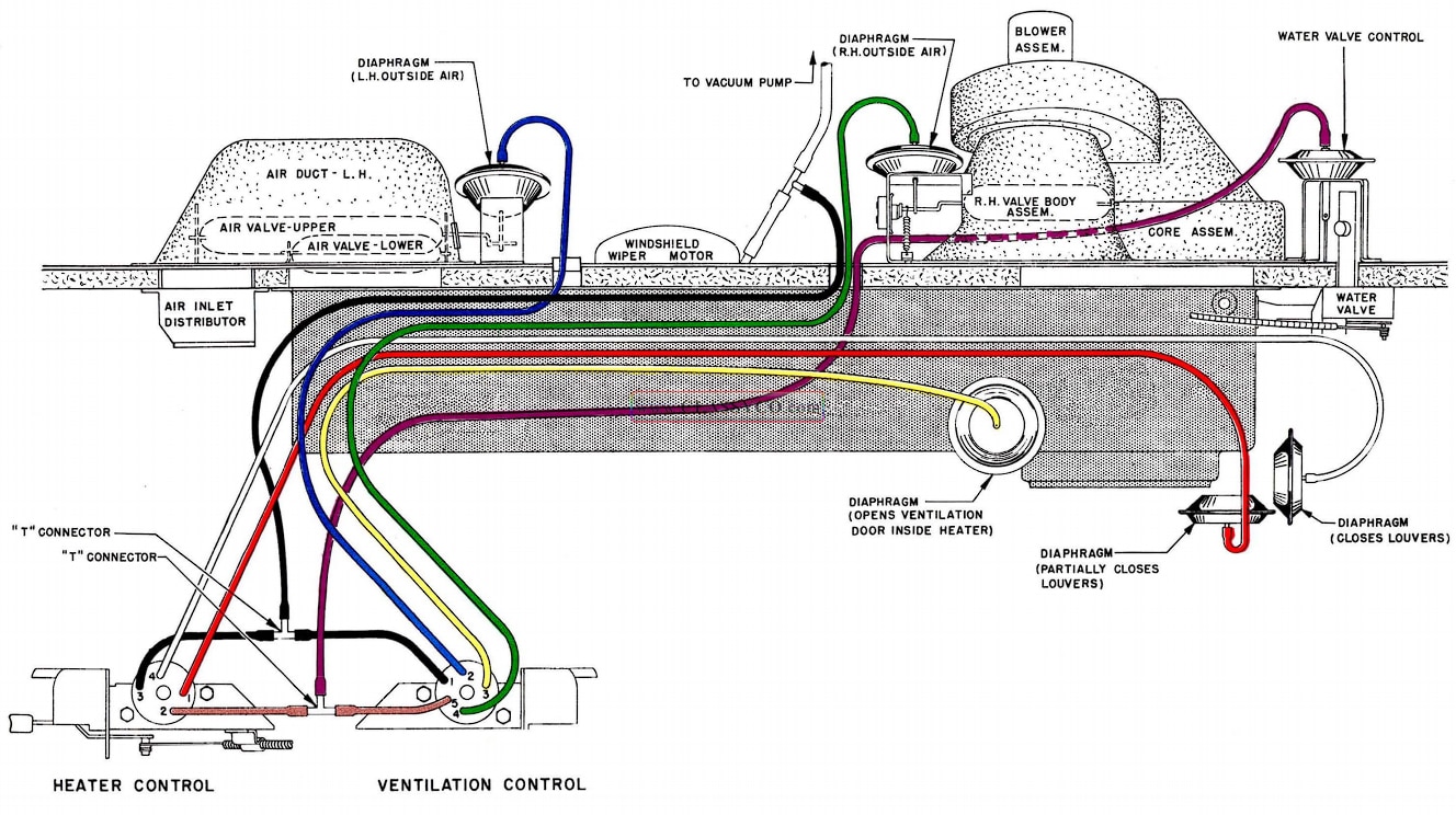
1957 Oldsmobile Schematic Diagram (Heater Only)
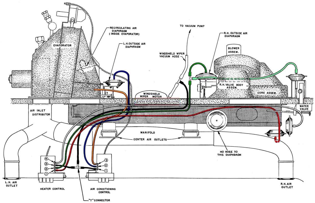
1957 Oldsmobile Schematic Diagram (Heater with Air Conditioning)
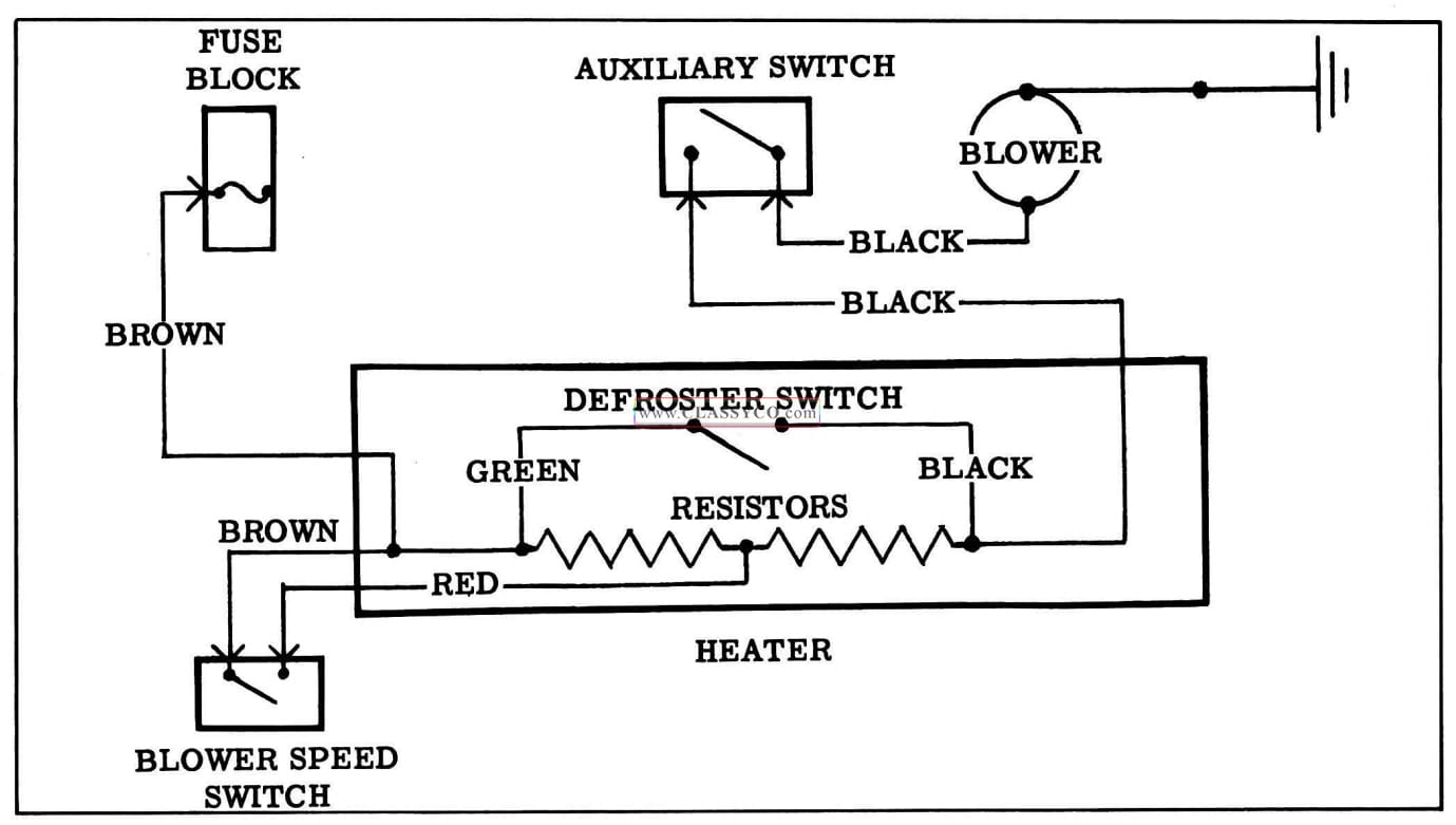
1957 Oldsmobile Wiring Diagram (3)