BRAKES
DESCRIPTION
The braking system consists of hydraulically operated service brakes that apply the brake shoes simultaneously at all four wheels, and a mechanically operated parking brake that applies the brake shoes at the rear wheels only.
When the service brake pedal is depressed, the piston or plunger in the master cylinder forces fluid under pressure to wheel cylinders at each wheel, which in turn, push the brake shoes against the brake drum. As the shoes contact the drum, the friction between the shoes and the rotating drum moves the primary shoe downward against the adjusting screw which acts as a link to transmit the force of the primary shoe to the lower end of the secondary shoe. With the upper end of the secondary shoe being held stationary by the anchor pin, the secondary shoe is ”wedged” against the drum. This ”wedging” action, due to frictional force, imparts the self energizing action to the braking effort and thereby decreases the effort required by the driver to stop the car.
The parking brake applies the rear brakes through cable and linkage by means of a parking brake pedal mounted below the instrument panel. The parking brake is released by a pull handle which is integral with the parking brake pedal assembly.
STOP LIGHT SWITCH
The standard brake stop light switch is mounted to the underside of the toe pan and is actuated by the movement of the brake pedal. This switch is not adjustable and the only service required is replacement when inoperative.
The power brake stop light switch is bolted on the brake pedal bracket and is actuated by an adjustable contact screw mounted on the brake pedal. For adjustment procedure refer to ELECTRICAL SECTION.
BRAKE PEDAL ADJUSTMENT
(Standard Brakes) (Fig. 7-1)
An incorrectly adjusted brake pedal can hold the master cylinder piston from fully returning to its released position, which will result in brake drag or lock-up. The brake pedal adjustment should be checked after a minor or major brake adjustment has been made.
- Depress brake pedal several times to be sure that pedal returns freely to stop. If pedal action is restrained by misalignment, lack of lubrication, etc., make the necessary corrections before proceeding.
- Check the sponge rubber pedal bumper between the pedal and the toe board. It should be slightly compressed when the brake pedal is in the released position.
- Depress the brake pedal and note the distance the pedal travels before the master cylinder push rod contacts the master cylinder piston. (This can readily be felt when depressing pedal by hand.) There should be at least 3/16″ free travel.
- If necessary to adjust, loosen check nut on push rod and while holding push rod rearward, adjust rod until at least 3/16″ free travel of the brake pedal is obtained and the sponge rubber pedal bumper is slightly compressed with the pedal in the released position.
- Tighten check nut and recheck adjustment.
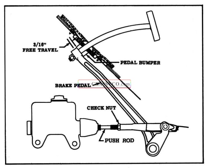
1957 Oldsmobile Brake Pedal Adjustment
MINOR BRAKE ADJUSTMENT
This adjustment should be made when there is excessive brake pedal travel due to wear of the brake lining (when pedal pad to floor clearance is less than 2″ for standard brakes; 1″ for power brakes.
- Fully release parking brake, then hoist car.
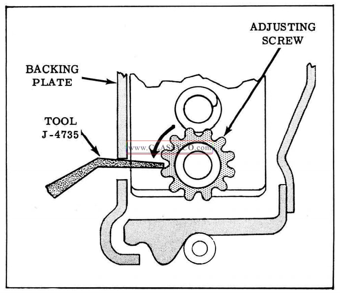
- Remove adjusting screw hole cover from backing plate. Expand brake shoes by turning adjusting screw using Tool J-4735, (See Fig. 7-2) until heavy drag is felt on brake drum, then turn adjusting screw in opposite direction approximately sixteen notches.
1957 Oldsmobile Expanding Brake Shoes
NOTE: If it is necessary to take up adjusting screw more than 50 notches, or car mileage indicates linings may be worn to rivets, then wheels and drums should be removed and linings inspected as outlined under BRAKE SHOE REPLACEMENT.
- Replace adjusting screw hole cover.
- Repeat steps 2 and 3 for remaining wheels.
- Fill master cylinder with brake fluid to proper level.
- For cars equipped with standard brakes, check brake pedal free travel as outlined under BRAKE PEDAL ADJUSTMENT.
MAJOR BRAKE ADJUSTMENT
(Anchor Pin Adjustment)
Whenever brake linings are replaced, it is necessary to adjust the anchor pin to insure full contact of the new linings to the brake drum. No attempt should be made to correct brake pull by changing the anchor pin setting once the linings have been seated.
- Remove wheels.
- Remove adjusting screw hole cover from backing plate, then expand brake shoe by turning adjusting screw using Tool J-4735 until heavy drag is felt on brake drum. (See Fig. 7-2)
- Release adjusting screw approximately sixteen notches until brake drum is free of drag.
- Insert a screw driver through the adjusting screw hole cover in the backing plate and force the adjusting screw toward the primary shoe, then turn the drum backward to force the lower end of the primary shoe against the drum. Check clearance at anchor and adjusting ends of the secondary shoe with a .015″ feeler inserted in the brake drum slot. If these clearances are not equal within plus or minus .002″, adjust anchor and adjusting screw as required. However, the clearance at the anchor end of the shoe should not be more than that at the adjusting screw end.
The exposed end of the anchor pin has a beveled face. The high side of the bevel designates the high side of the eccentric. Hold anchor pin and tighten anchor pin lock nut as tightly as possible. (See Fig. 7-3)
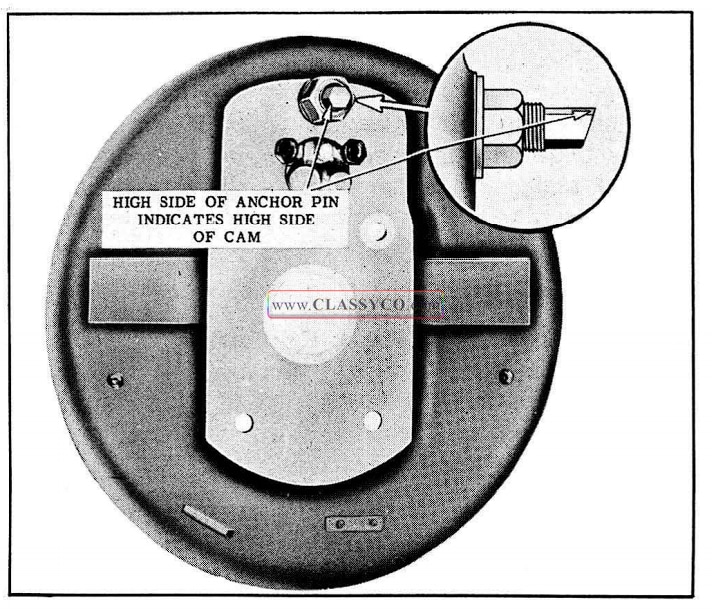
1957 Oldsmobile Anchor Pin Adjustment
- Repeat steps 2, 3 and 4 on remaining brakes.
- Install wheels.
- Fill master cylinder with brake fluid to proper level.
- For cars equipped with standard brakes, check brake pedal free travel as outlined under BRAKE PEDAL ADJUSTMENT.
PARKING BRAKE ADJUSTMENT
- Release parking brake.
- Make minor brake adjustment if there is excessive brake pedal travel. (See MINOR BRAKE ADJUSTMENT)
- Adjust the front cable so that intermediate lever is held from seating itself at the rear end of the slot in the left hand “X” member by 1/2″. (See Fig. 7-4)
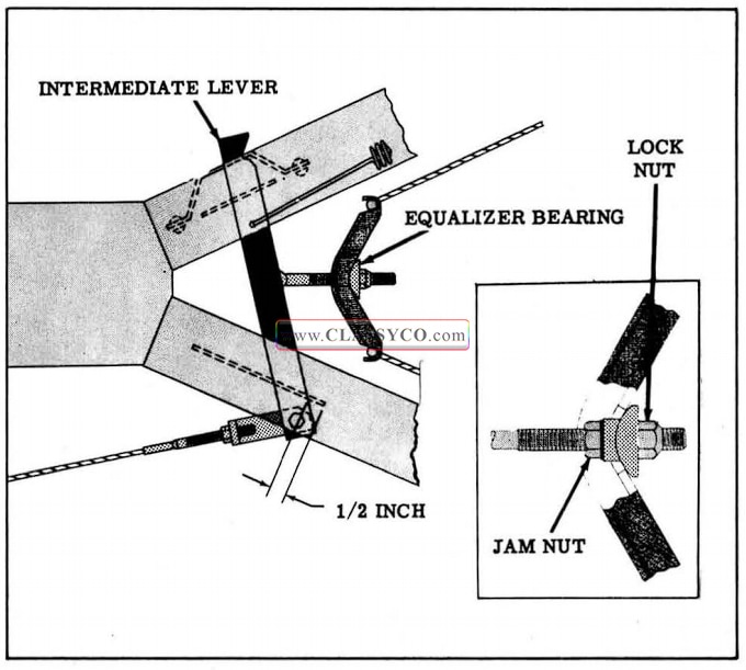
1957 Oldsmobile Parking Brake Linkage
- Adjust equalizer to remove all possible slack from the rear brake cables without moving the brake shoes from the released position.
BRAKE SHOE REPLACEMENT (Fig. 7-5)
When brake lining replacement is necessary, it is recommended that all the linings are replaced. However, in some cases replacement of both front wheel or both rear wheel linings is permissible.
Under no condition should the linings of one wheel or one shoe be replaced.
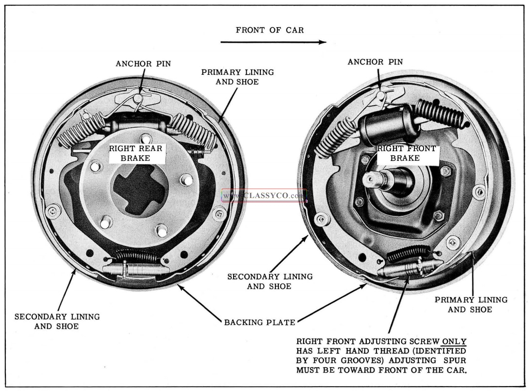
1957 Oldsmobile Brake Details
For brake lining inspection, lubrication of brake parts, or replacement of linings and shoes, proceed as follows:
- Hoist car and remove wheels.
- Remove brake drum assemblies.
- Check linings for wear. (If linings are worn nearly flush with rivets, new linings should be installed.)
- Examine brake drum braking surfaces for smoothness. Slight scores or scratches may be removed by the use of emery cloth.
NOTE: Grooves extending around the entire braking surface of the brake drum are permissible providing the edges of the grooves that contact the shoes are smooth.
If, after this has been done, the surfaces are not smooth, the drums should be turned to .060″ greater than the original inside diameter; that is, after being turned, the diameter should be 11.060″. Oversize brake linings should be used with turned drums.
- Remove shoes and disconnect parking brake cables from operating levers.
- Remove parking brake cable equalizer, then disconnect cables from equalizer.
- Clean all rust from shoes, inner surfaces of brake backing plates, and all contacting points. Apply a thin coat of Lubriplate or its equivalent to the backing plate ledges against which the shoes operate, and all other metal contacting points.
- Clean exposed portions of parking brake cables. Pull cables rearward through conduits, lubricate freely with Brake Cable Lubricant (Lithium Soap Grease), and return to normal position. Remove any excess lubricant.
- Tighten all brake backing plate mounting bolts 55 to 60 ft. lbs. torque.
- Reassemble brakes, connecting parking brake cables and equalizer.
- Install brake drum assemblies, being sure that adjusting screws are backed off sufficiently.
IMPORTANT: The RIGHT FRONT AND LEFT REAR BRAKE ADJUSTING SCREWS have left hand threads and can be readily identified by four grooves on the body. When installing the adjusting screw in the right front or left rear brake assembly, the “spur” end of the screw must be toward the front of the car.
- Adjust front wheel bearings. (See FRONT SUSPENSION SECTION)
- Check anchor pin settings and adjust if necessary. (See MAJOR BRAKE ADJUSTMENT)
- Adjust brake shoes as described under MINOR BRAKE ADJUSTMENT.
- Adjust parking brake cables as outlined under PARKING BRAKE.
- Fill master cylinder to prescribed level.
- Replace wheels and test brakes.
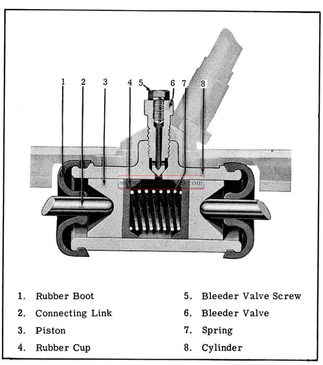
SERVICING MASTER AND WHEEL CYLINDERS
1957 Oldsmobile Wheel Cylinder Details
NOTE: For information pertaining to servicing of the power brake master cylinder, refer to POWER BRAKES.
CAUTION: Do not attempt to recondition a brake master or wheel cylinder bore as a means of salvaging the cylinders. Reconditioning of the bores leaves the walls sufficiently rough to cause premature failure of the rubber cups. It also enlarges the bore to the extent that the standard size pistons will no longer fit properly. OVERSIZE PISTONS AND CUPS ARE NOT AVAILABLE.
Master cylinder and wheel cylinder repair kits contain a complete set of standard parts to repair one cylinder. The diameters of wheel cylinder pistons and rubber cups are 1-3/32″ for the front and 31/32″ for the rear brakes. The diameters of the master cylinder piston and rubber cups are 1″. When new cups or pistons are installed the correct size must be used.
NOTE: When reassembling the master cylinder, the small coils of conical spring must be placed over the check valve and the large coil against the primary cup. (See Fig. 7-7)
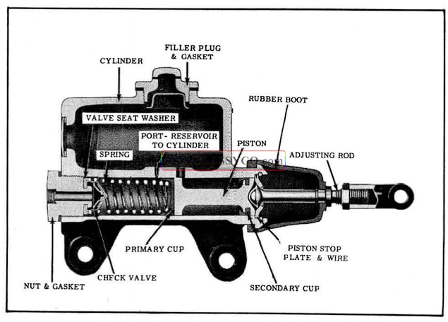
1957 Oldsmobile Master Cylinder Details
BLEEDING OF LINES
Whenever a line is disconnected from any wheel, it is necessary that the wheel cylinder be bled. 1f the hydraulic line is disconnected from the master cylinder or the brake pedal has a spongy feeling, each wheel cylinder must be bled to expel air from the system.
NOTE: Power brakes can be bled in the same manner as a standard brake system. If pressure bleeding equipment is not available, DO NOT use the vacuum assist. The engine should not be running and the vacuum reserve should be depleted by applying the brake before starting the bleeding procedure.
The system can be bled manually or by using pressure bleeding equipment.
To bleed the system, the following procedure is recommended:
The correct sequence for bleeding is left front, right front, left rear, right rear.
- If brakes are to be bled manually, fill the brake reservoir with G.M. Brake Fluid No. 11 and KEEP AT LEAST ONE-HALF FULL OF FLUID DURING THE BLEEDING OPERATION.
- If brakes are to be bled with pressure equipment, connect the tank to the brake reservoir and raise the pressure in the brake system to 20 to 30 p.s.i.
- Remove bleeder valve screw from wheel cylinder to be bled, then attach rubber bleeder tube to bleeder valve. (See Fig. 7 -8) THE TUBE MUST HANG SUBMERGED IN A CLEAN CONTAINER PARTIALLY FILLED WITH G.M. BRAKE FLUID NO. 11 DURING THE BLEEDING OPERATION.
- Unscrew bleeder valve three quarters of a turn and watch flow of fluid from rubber bleeder tube. When all air bubbles cease to appear, close bleeder valve.
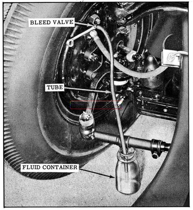
1957 Oldsmobile Bleeding Brakes
NOTE: If brakes are bled without the aid of pressure equipment, the brake pedal must be operated during this operation to force the fluid from the bleeder hose. To do this, open the bleeder valve, fully depress the brake pedal, then slowly release pedal until it is in the fully released position. Continue operating pedal until liquid, containing no air bubbles, emerges from bleeder tube. Close bleeder valve.
- Remove bleeder tube and install valve screw.
- Repeat the above steps on the remaining wheel cylinders if the entire system is to be bled.
- If the brakes were bled manually, check fluid in reservoir and replenish if necessary, after the bleeding operation has been completed.
FLUSHING HYDRAULIC SYSTEM
Whenever mineral oil has been introduced into the hydraulic system, or foreign material has dis colored or thickened the brake fluid, the entire system should be thoroughly flushed with Declene Flushing Fluid. The Declene Flushing Fluid is introduced into the master cylinder reservoir and expelled at each wheel cylinder in the same manner as the bleeding operation (See BLEEDING OF LINES) except that the flushing fluid is forced through the system until the fluid emerges clear in color at the wheel cylinders.
When flushing is completed, bleed the hydraulic system with G.M. Brake Fluid No. 11 as outlined under BLEEDING OF LINES until all flushing fluid and air is expelled from the lines.
BRAKE PEDAL (STANDARD BRAKES), REMOVAL AND REPLACEMENT (Fig. 7-9)
- Disconnect pedal rod from brake pedal.
- Disconnect pedal return spring.
- Remove retainer from end of pedal pivot shaft.
- Remove pivot shaft cap screw.
- Push pivot shaft through pedal.
- Loosen master cylinder push rod check nut. (If check nut is just loosened, it will facilitate reassembly.)
- Turn master cylinder push rod out of master cylinder clevis.
- Disassemble clevis from brake pedal.
To assemble, reverse sequence of operations and adjust pedal clearance. (Refer to BRAKE PEDAL ADJUSTMENT)
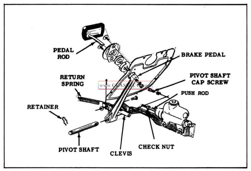
1957 Oldsmobile Brake Pedal Assembly
POWER BRAKES
DESCRIPTION
IMPORTANT: Early production cars equipped with Bendix power brakes will have the 1956 unit (vacuum reaction type). For information pertaining to this unit, refer to the 1956 shop manual.
Oldsmobile uses both Bendix and Moraine units. The Bendix and the Moraine assemblies can be distinguished by the difference in the master cylinder castings. The Bendix master cylinder is cast of light alloy metal and the Moraine master cylinder is of cast iron. Internally, the Bendix and Moraine power brake units differ in construction, but both units are designed to seal off the vacuum from the units when the pedal is in the released position.
This design, combined with a vacuum check valve traps manifold vacuum in the reservoir at the highest manifold vacuum available, making possible three or four normal brake applications after the engine has been shut off for several hours or more. Should the engine stall, several applications of the brakes can still be made. If the vacuum supply were depleted, application could be made manually as in a conventional system; however, more effort is required due to the lack of power assist.
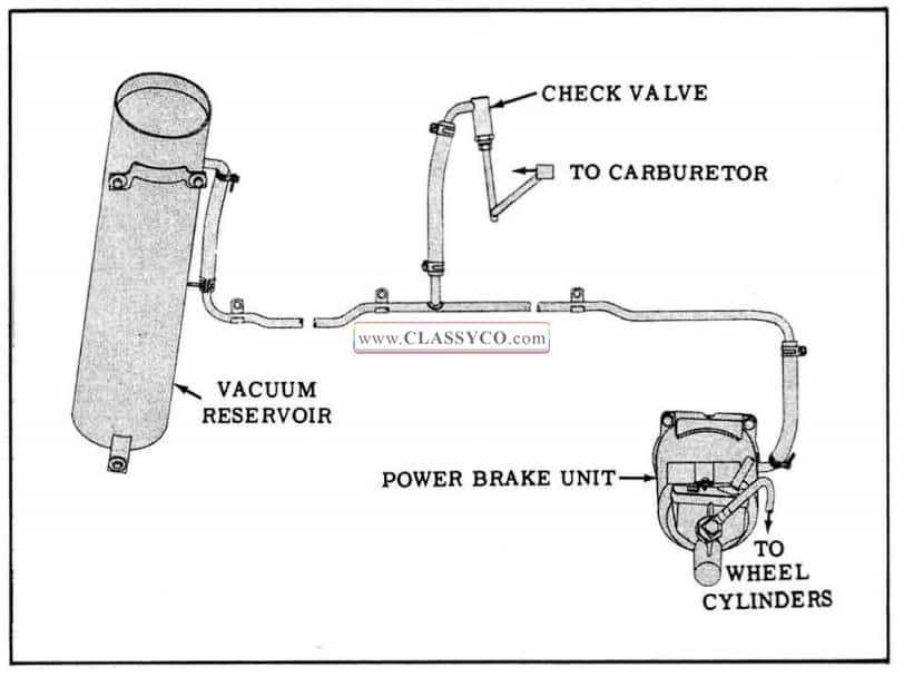
1957 Oldsmobile Power Brake Layout
PERIODIC SERVICE
Each time the car is in the service department, the brake pedal height should be observed. Brakes should be adjusted when the pedal pad to floor clearance is less than 1″ with brakes applied and engine running. (See MINOR BRAKE ADJUSTMENT)
Each time the chassis is lubricated, check level of brake fluid in reservoir. Fluid level should be high enough to register on the dip-stick. Replenish as necessary with G.M. Brake Fluid No. 11. Also, brake hoses and lines should be inspected for signs of chafing, deterioration or other damage.
Each time the power brake unit is removed from the car, or whenever the air cleaner is readily accessible, the air filter element should be cleaned in solvent and air dried.
REMOVAL AND REPLACEMENT
Vacuum Reservoir
The vacuum reservoir is located under the right front fender on the fender filler plate. No service is required other than replacement, for leakage. To remove the vacuum reservoir, the right fender must be disconnected at the cowl.
Power Brake Unit
- Disconnect positive battery cable at junction block on right fender filler plate. Disconnect solenoid lead wire (purple) from wiring har ness, then pull cable through sleeve on power brake.
- Disconnect brake line at the power brake master cylinder. Use care to prevent dirt entering the hydraulic line and bend the line so that the open end is above the fluid level in the line to prevent loss of fluid. Plug the master cylinder outlet with a rubber stopper.
- Disconnect leads from stoplight switch and fold back floor mat.
- Remove three brake pedal bracket attaching bolts and lockwashers (A), Fig. 7-11. Remove bracket and pedal assembly.
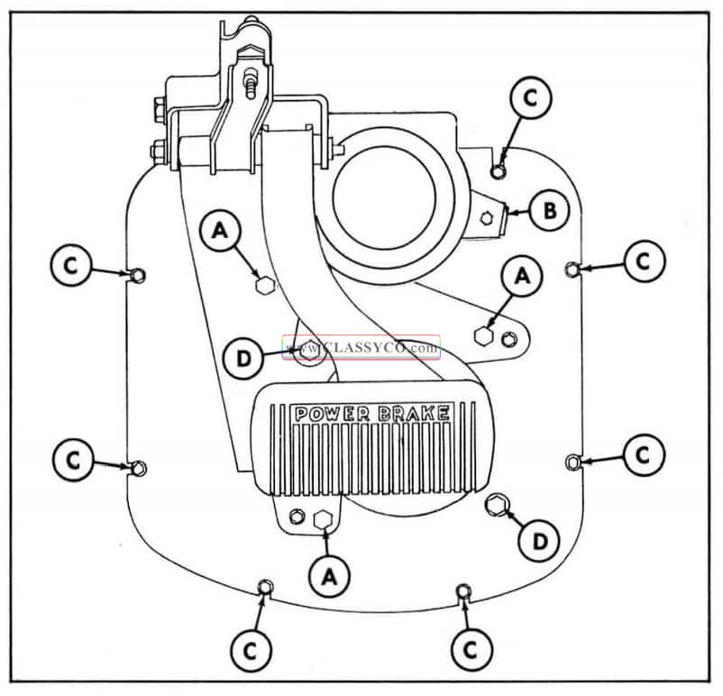
1957 Oldsmobile Power Brake Attaching Screws
- Remove mast jacket grommet and retainer clamp (B) and slide grommet and retainer up mast jacket.
- Remove floor cover plate attaching screws (C).
- Remove speedometer cable from clips.
- Remove the two cover plate to power cylinder bolts, (D), and remove the cover plate while positioning the power brake unit so it rests on the edge of the opening in the toe pan.
- Disconnect the vacuum hose and remove the power brake unit through the toe pan opening.
NOTE: When reinstalling hose, position the clamp so the screw head may be reached from below the car.
To replace, scrape off old sealing compound, then place a 5/16″ bead of medium bodied sealer around entire toe pan groove and reverse sequence of operations. The master cylinder may be filled before installation. Avoid depressing the push rod until hydraulic line is connected. Torque brake pedal attaching bolts (A) and cover plate to power cylinder bolts (D) 30 to 45ft. lbs. (See Fig. 7-11) Fill master cylinder with G.M. Brake Fluid No. 11 and bleed entire system. (See BLEEDING OF LINES) Following replacement, test brakes and adjust stoplight switch. (See ELECTRICAL SECTION)
MORAINE POWER BRAKE
PRINCIPLES OF OPERATION
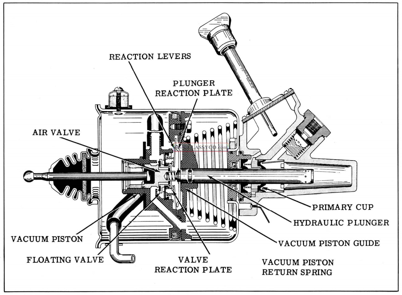
Released Position (Fig. 7-12)
In the released position, both sides of the vacuum piston are open to atmospheric pressure; therefore, the piston is balanced in atmospheric pressure and the vacuum piston is held in its released position by the piston return spring. This condition is accomplished by the following.
Vacuum is shut off within the vacuum piston since the floating valve is held on its seat by the floating valve diaphragm spring. The air valve and push rod assembly is held in its released position away from the floating valve by the air valve return spring. Atmospheric pressure, after passing through the air cleaner, enters the power cylinder at the rear side of the vacuum piston. It then passes through holes in the vacuum piston to the air valve where it is admitted to the forward side of the vacuum piston.
The valve reaction plate is held against the reaction levers by the floating valve diaphragm spring which also assists the reaction spring in holding the reaction levers and plunger reaction plate against their stops.
The hydraulic plunger, being attached to the vacuum piston assembly, is also held in the re leased position by the piston return spring. In this position, the radial holes in the forward end of the plunger are open to the grooves on the inner diameter of the plunger bearing and fluid can flow freely in either direction between the hydraulic cylinder and the fluid reservoir. This compensates for expansion, contraction, or leakage of fluid in the hydraulic system. The fluid in the lines to the wheel cylinders is trapped by the residual check valve, thus maintaining pressure in the lines as in a conventional braking system.
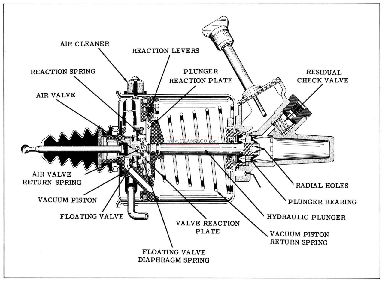
1957 Oldsmobile Released Position
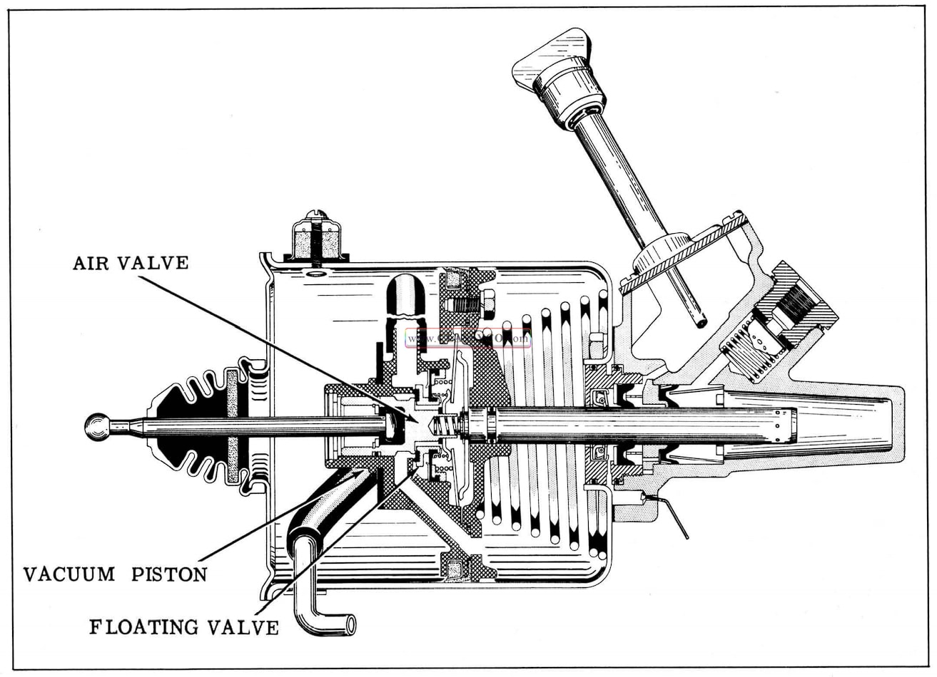
Applying Position (Fig. 7-13)
In the applying position, vacuum exists on the forward side of the vacuum piston and atmospheric pressure on the rear side of the vacuum piston overcomes the piston return spring and forces the vacuum piston in the apply position. This condition is accomplished by the following:
Atmospheric pressure is blocked off from the forward side of the vacuum piston as the air valve contacts the floating valve. Further movement of the air valve pushes the floating valve from its seat in the vacuum piston and permits vacuum to be communicated to the forward side of the vacuum piston. Atmospheric pressure on the rear side of the vacuum piston moves the piston and the hydraulic plunger in the applied direction.
As the hydraulic plunger moves forward, the radial holes at the end of the plunger pass the primary cup, sealing off the fluid reservoir from the hydraulic cylinder. Further movement of the plunger in the applied direction forces fluid out of the master cylinder under pressure through the hydraulic lines into the wheel cylinders to apply the brakes.
As the pressure build-up takes place in the master cylinder, force on the end of the plunger moves the plunger reaction plate away from the vacuum piston guide, which causes the reaction levers to pivot against the valve reaction plate. The valve reaction plate then transfers the force to the air valve and push rod assembly, thus giving the driver brake “feel”. By design, this brake “feel” is such that approximately 40% of the load on the hydraulic plunger is supplied by the driver, while the remainder is supplied by atmospheric pressure on the rear side of the vacuum piston.
1957 Oldsmobile Applying Position
Holding Position (Fig. 7-14)
When the desired brake application has been reached, the driver stops increasing the brake pedal force, which in turn holds the push rod and air valve stationary. The vacuum piston will continue to move forward as in the applied position until its seat rests against the floating valve. At this point, both the air valve and the floating valve are closed and no further movement takes place until the force on the pedal is either decreased or increased.
1957 Oldsmobile Holding Position
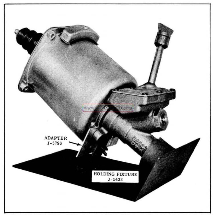
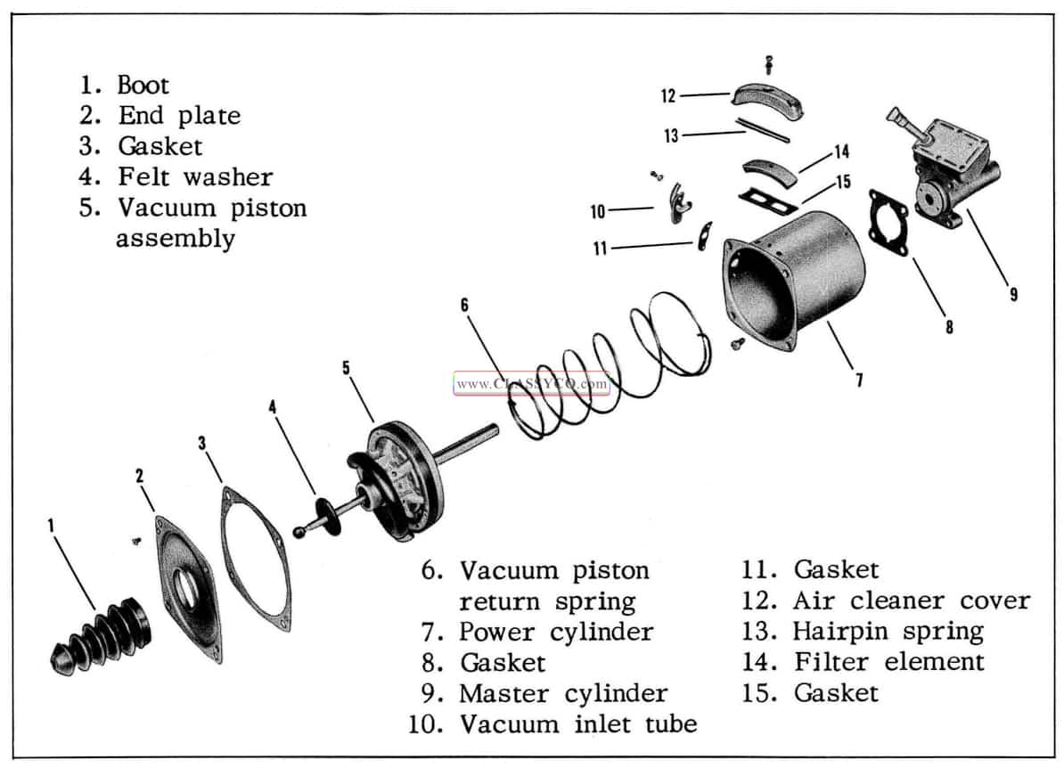
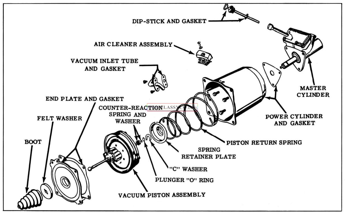
DISASSEMBLY OF MORAINE POWER BRAKE (Fig. 7-16)
NOTE: Use extreme care to keep mineral oil or grease from coming in contact with hydraulic parts.
- Clean all dirt from the outside of the power brake unit. Remove dip-stick and gasket and empty brake fluid from master cylinder casting.
- Mount unit in holding fixture J-5433-A with adapter J-5796 if available. (See Fig. 7-15) If holding fixture is not available, clamp master cylinder end of unit in a vise.
1957 Oldsmobile Power Brake Holding Fixture
- Remove the screw attaching air cleaner unit to power cylinder. Removal of the air cleaner must precede disassembly of internal parts to avoid damage to large leather piston packing inside power cylinder. Disassemble air cleaner.
- Remove boot and felt washer.
- Remove the two end plate attaching screws, then remove the end plate and gasket.
- Remove rubber hose from vacuum inlet tube inside the power cylinder.
- Push the vacuum piston assembly back into the power cylinder so that it will not interfere with the inlet tube removal. Holding the vacuum piston in this position with one hand, remove the two screws that hold the vacuum inlet tube to the outside of the power cylinder. Removal of the vacuum inlet tube permits the vacuum piston return spring to force the vacuum piston assembly out of the power cylinder under heavy spring tension.
- Remove the large vacuum piston return spring from the power cylinder.
- Scribe alignment marks across power cylinder and master cylinder casting. Remove the four cap screws from the inside of the power cylinder, then remove the power cylinder and gasket.
NOTE: The power cylinder pilots on the extended area of the cylinder plug and should be removed carefully.
1957 Oldsmobile Moraine Power Brake
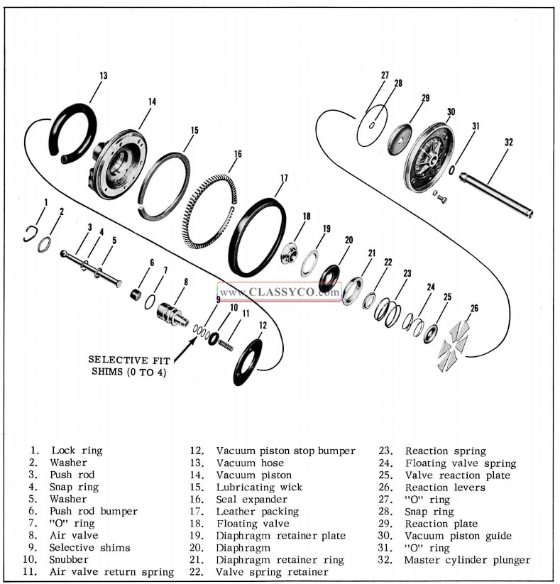
DISASSEMBLY OF VACUUM PISTON (Fig. 7-17)
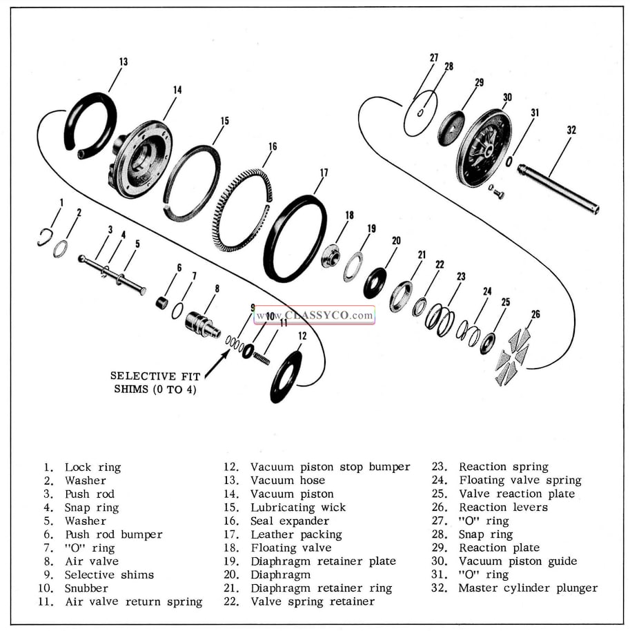
1957 Oldsmobile Vacuum Piston Assembly
- Remove vacuum hose from vacuum piston assembly.
- Remove lock ring as shown in Fig. 7-18 and remove push rod and air valve assembly. Remove the stop plate washer.
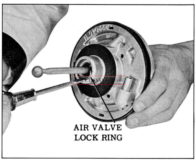
1957 Oldsmobile Removing Air Valve Lock Ring
- Hold the vacuum piston assembly as shown in Fig. 7-19, then carefully pull out air valve and push rod. The air valve return spring, snubber, and valve shims will come out with the air valve.
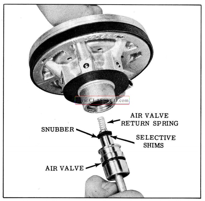
1957 Oldsmobile Removing Air Valve
NOTE: Observe the number of shims, if any, on the air valve.
- Remove snubber, shims, and “O” ring from air valve.
- It is not necessary to remove the push rod from the air valve unless it is noisy or excessively loose. If necessary, remove TruArc snap ring from inside of air valve with Tru-Arc internal No. 1 pliers (J-5403). Pull out washer and push rod from air valve, then remove rubber bumper from end of push rod.
- Set the vacuum piston assembly on hub end and loosen the four vacuum piston cap screws. (See Fig. 7-20) Press down on the piston guide and remove the screws, then lift off the piston guide and hydraulic plunger assembly. Remove “O” ring from vacuum piston guide.
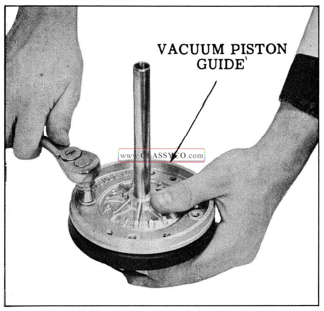
1957 Oldsmobile Removing Vacuum Piston Guide
- Slide the vacuum piston guide off the hydraulic plunger and remove the “O” ring from the plunger.
- If necessary to separate the reaction plate or plunger, remove Tru-Arc ring with Tru-Arc external No. 2 pliers (J-4880).
- From counterbore of vacuum piston, remove six reaction levers, reaction spring, valve reaction plate, and floating valve spring.
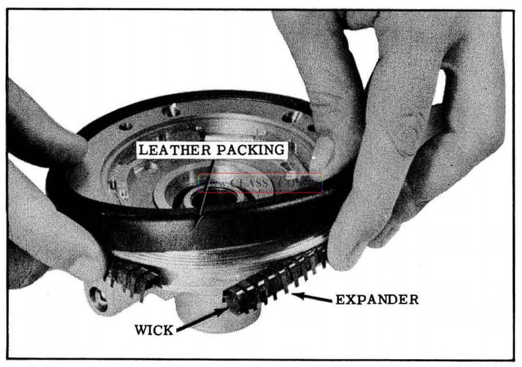
- Lift leather packing off vacuum piston, then remove the expander and wick. (See Fig. 7-21)
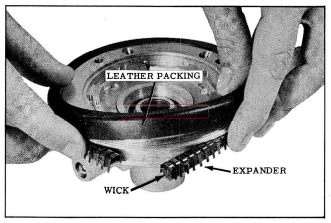
1957 Oldsmobile Removing Leather Packing
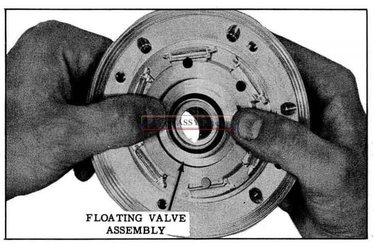
- Pull the floating valve assembly from the vacuum piston. (See Fig. 7-22)
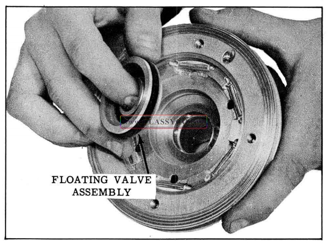
1957 Oldsmobile Removing Floating Valve Assembly
- If necessary to disassemble floating valve, proceed as follows:
- Unseat valve spring retainer with small screw driver. (See Fig. 7-23)
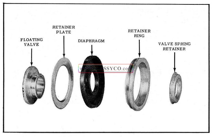
1957 Oldsmobile Floating Valve Assembly
- Press the floating valve through the diaphragm. This also frees the diaphragm retainer plate.
- Remove the diaphragm from the groove in the retainer ring.
- Remove rubber vacuum piston stop washer from hub flange of vacuum piston.
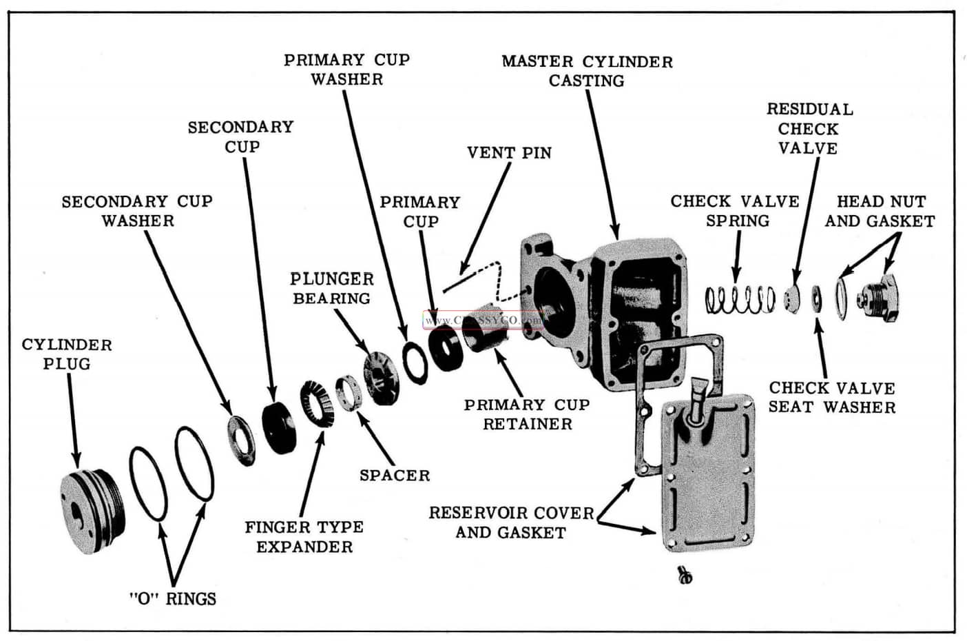
DISASSEMBLY OF MASTER CYLINDER (Fig. 7-24)
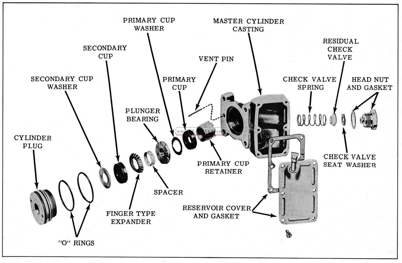
1957 Oldsmobile Master Cylinder
- Clamp master cylinder. casting in vise with cylinder plug up. Remove cylinder plug using special spanner wrench Tool J-5794. (See Fig. 7-25)
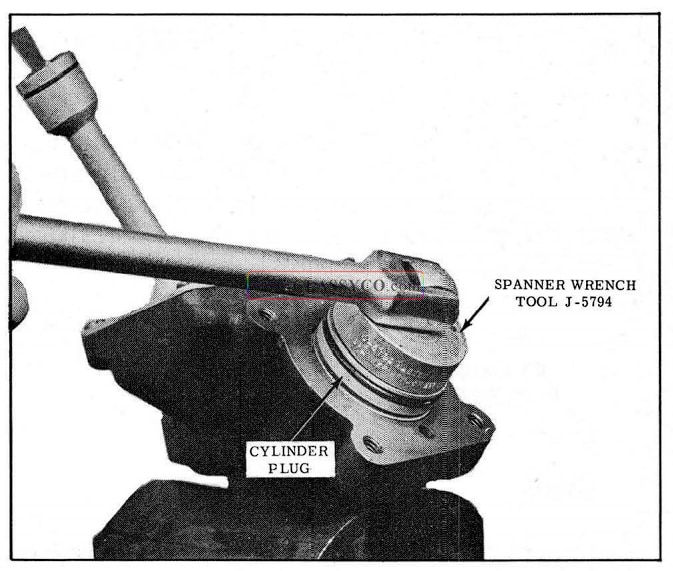
1957 Oldsmobile Removing Cylinder Plug
- Remove two “O” rings from outside diameter of cylinder plug.
- Remove secondary cup and washer from inside of plug. DO NOT attempt to remove the seal assembly from cylinder plug. If the vacuum seal is defective, the cylinder plug and vacuum seal must be replaced as an assembly.
- From the bore of the master cylinder, lift out expander, spacer, plunger bearing, washer, primary cup, and retainer.
- Remove head nut assembly and copper gasket.
CAUTION: The head nut is under spring tension. Guard against the residual valve spring falling from bore. Remove residual check valve and spring. Remove rubber check valve seat washer from button on head nut.
- Scratch alignment mark on reservoir cover and casting. Remove reservoir cover and gasket.
- Inspect vent on underside of casting. If vent hole is clogged and cannot be cleaned out so that the pin rides free, the pin may be straightened and removed through the counterbore end of the vent hole.
CLEANING AND INSPECTION MORAINE POWER BRAKE
CLEANING
Thoroughly wash all parts in alcohol, blow out all passages, and air dry. Place clean parts on clean paper.
INSPECTION
Power Cylinder
In addition to parts contained in repair kits, inspection of parts should be made as directed below.
Inspect for scoring, pitting, dents, nicks, or damaged threads. Small imperfections may be smoothed out by fine crocus cloth; replace if badly damaged.
Master Cylinder Casting
Examine bore down one inch from open end. For primary cup to seal properly, this portion of bore must be free from scores, deep scratches, and corrosion. Machined bore of the master cylinder may be cleaned with crocus cloth. The three gasket surfaces must be smooth and free of nicks. Check for cracks and damaged threads. Passages in reservoir should be clean.
Cylinder Plug Assembly
Cavities should be free of imperfections to allow good seat for secondary cup. Check outside sur faces for damaged threads and clean grooves. Be sure small radial holes are open and clean. Inspect seal for wear and proper tension. The vacuum seal and cylinder plug are serviced as an assembly.
Head Nut Assembly
Check for damaged threads and smooth seat. Replace if damaged.
Residual Check Valve and Spring
Check for distortion and deterioration of rubber.
Dip-Stick
Check for damaged threads or badly worn gasket. Be sure breather holes are clean and open.
Hydraulic Plunger
Examine carefully for nicks, corrosion, and abrasion. Radial holes in counterbore should be open. If scored or pitted, replace with new plunger.
Hydraulic Plunger Bearing
Grooves and holes must be clean. Check fit of hydraulic plunger in bearing. Replace if worn or damaged.
Vacuum Inlet Tube
Make sure braze is secure and tube plate is not distorted.
Air Filter Assembly
Replace filter element if filled with dirt or damaged. Replace rubber gasket if cracked or torn.
Air Valve
Check for scratches, dents, distortion, or corrosion on both outside and inside surfaces. Check seat for smoothness and flatness. Should have free sliding fit when inserted in vacuum piston bore. Replace if worn or damaged.
Floating Valve Assembly
Check for distortion of metal parts and deterioration or abrasions of rubber parts. Replace if worn or damaged.
Vacuum Piston and Guide
Check for cracks, distortion, damaged lever seats or rough and uneven floating valve seat. Be sure all openings and passages are clean.
Reaction Levers
Check for distortion. The levers may be straightened with a mallet if they are not badly distorted.
ASSEMBLY OF MORAINE POWER BRAKE UNIT
ASSEMBLY OF MASTER CYLINDER (Fig. 7-26)
- Place residual check valve spring in 1″ threaded bore in master cylinder casting. Nest residual valve assembly into the valve spring. Button check valve seat onto head nut and fit copper head nut gasket over threaded end of head nut. Screw head nut in place carefully to avoid tilting the check valve. Torque 80 to 90ft. lbs.
- Install reservoir cover and new gasket. Note cover to reservoir casting alignment marks to insure filler tube is correctly located. Install dip-stick and gasket.
- Clamp master cylinder in vise in vertical position with large counterbore facing upward. Wipe counterbores and threads with a thin coating of brake fluid. Place conical primary cup retainer with notched end down into open end of bore; press primary cup into bore with lip facing and centered over small end of conical retainer. Place thin blue steel primary cup washer in place on back of primary cup. Place bearing into bore with notched side up, making sure that the hub of the bearing fits into the counterbore on the back of the primary cup. Place spacer on top of bearing, and position new expander on top of spacer with fingers pointing down, making sure spacer and expander are centered over bearing.
- Assemble the cylinder plug as follows: Install two new “O” rings in the grooves on 0.0.
CAUTION: Do not place “O” ring in second groove that has four small vent holes. Install secondary cup washer and seat secondary cup with ribbed side up in cylinder plug.
- Lubricate the cylinder plug “O” rings, secondary cup, and leather seal, with shock absorber fluid. Carefully install the cylinder plug assembly. Use special spanner wrench, Tool J-5794, for tightening cylinder plug. Torque 20 to 30 ft. lbs.
- If vent pin was removed, replace in vent hole. The vent pin should protrude through bottom of vent hole. Bend protruding end to approximately 45° to hold in place.
- Align new power cylinder gasket on the master cylinder casting so that the vent passage is open. Observe alignment marks and install the power cylinder on the master cylinder plug. Attach power cylinder to master cylinder with four cap screws. Torque to 12 ft. lbs.
1957 Oldsmobile Master Cylinder (2)
ASSEMBLY OF VACUUM PISTON (Fig. 7-27)
1957 Oldsmobile Vacuum Piston Assembly (2)
- If floating valve was disassembled, proceed as follows:
a. it the lip of the rubber diaphragm over the small diameter of the diaphragm retainer ring, (See Fig. 7-28)
1957 Oldsmobile Floating Valve
b. Hold the flat side of the diaphragm retainer plate against the diaphragm, then press the floating valve into place in the diaphragm.
c. Press the valve spring retainer over the hub of the floating valve and the inner flange of the diaphragm. - Push the floating valve assembly into the vacuum piston as shown in Fig. 7-29.
1957 Oldsmobile Installing Floating Valve Assembly
- Install the felt wick in the expander, then in stall the wick and expander assembly in the groove of the vacuum piston with the expander fingers pointing toward hub. If new wick is used, saturate with shock absorber fluid. While holding the wick and expander in place, install leather packing. (See Fig. 7 -30)
1957 Oldsmobile Installing Leather Packing
NOTE: If new leather packing is installed, use cardboard cylindrical container to confine packing during installation.
d. Wipe outside diameter of floating valve assembly lightly with Dow Corning No. 4 Silicone Grease. - Snap floating valve diaphragm spring over valve spring retainer. Nest valve reaction plate over diaphragm spring. Seat reaction spring in recess of valve diaphragm retainer ring. (See Fig. 7-31)
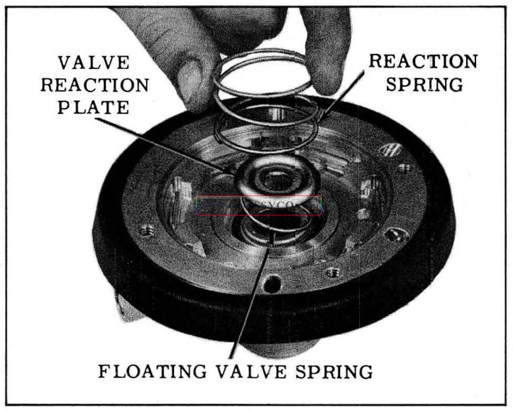
1957 Oldsmobile Installing Reaction Spring
- Place reaction levers in vacuum piston. (See Fig. 7-32)
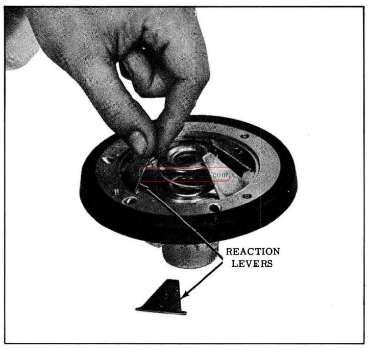
1957 Oldsmobile Installing Reaction Levers
- Install new “O” ring in groove in hydraulic plunger. If plunger reaction plate was removed, install on plunger with raised edge extending away from plunger using Tru-Arc external No. 2 pliers (J-4880). (See Fig. 7-33)
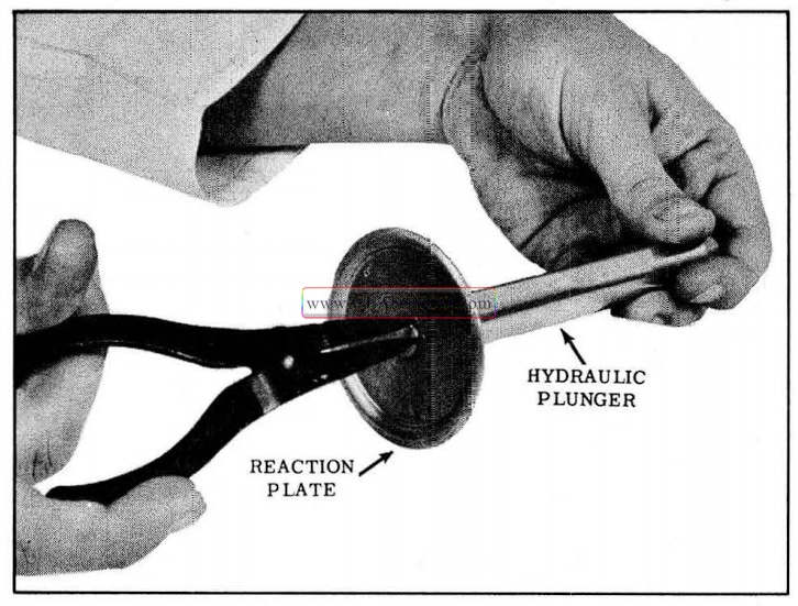
1957 Oldsmobile Installing Reaction Plate
- Fit new “O” ring onto machined hub of vacuum piston guide.
- Lightly lubricate plunger “O” ring and bore of vacuum piston guide with Dow Corning No. 4 Silicone Grease.
- Seat the plunger and reaction plate assembly on the reaction levers, then press down quickly until the reaction levers are held in a flat position. (See Fig. 7 -34) Be sure each lever is properly seated.
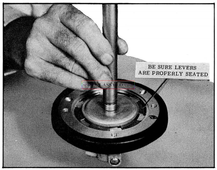
1957 Oldsmobile Depressing Reaction Levers
- While holding the plunger in position, slide the piston guide down the plunger and into position on vacuum piston.
- Align the raised holes in the piston guide with the threaded holes in the vacuum piston, then install the attaching screws. Torque 5 to 6 ft. lbs.
- Install new rubber vacuum piston stop washer to hub flange of vacuum piston with Super Weatherstrip Adhesive.
- If push rod was removed from air valve, position rubber bumper over end of push rod and insert assembly into air valve. Seat washer against push rod bumper and install snap ring with Tru-Arc internal No. 1 pliers (J-5403).
- Place new “O” ring in narrow groove on out side of the air valve. Coat “O” ring and out side diameter of air valve with light coat of Dow Corning No. 4 Silicone Grease.
- Check to determine number of shims to be used as follows:
NOTE: Visually check position of valve reaction plate in the vacuum piston. The hole in the reaction plate must be centered in relation to the bore in the piston hub.
a. Place 4 new shims and snubber on Tool J-5805 and insert gauge into bore of vacuum piston as shown in Fig. 7-35. The body of the gauge will rest on the valve reaction plate, and the pin will extend through the hole in the plate and contact the end of the hydraulic plunger.
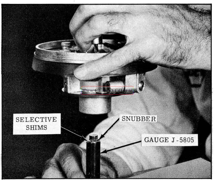
1957 Oldsmobile Installing Gauge J-5805
b. Turn the vacuum piston so the gauge is on the top and observe the position of the pin in the gauge body.
c. If the pin is flush with or less than .010″ above the body, no further adjusting is required. (See Fig. 7-36)
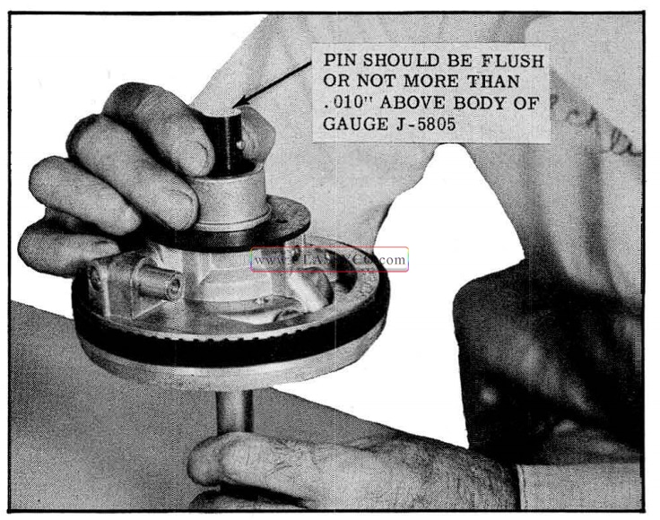
1957 Oldsmobile Checking Pin Position of Gauge J-5805
d. If the pin is below the top of the gauge body, remove shims one at a time until the pin is flush or not more than .010″ above gauge body.
e. If pin is more than .010″ above the top of gauge body, disassemble and inspect for bent reaction levers, reaction plate, or valve plate.
16. After proper number of shims has been determined, place the shims and snubber on small diameter of air valve, then insert valve return spring into small bore in air valve.
17. Holding the vacuum piston assembly with master cylinder plunger pointing upward, insert from below, the air valve, spring, and push rod assembly into the hub end of the vacuum piston. (See Fig. 7-37)
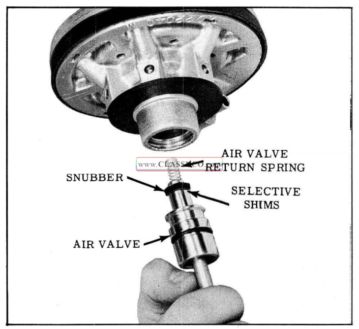
1957 Oldsmobile Installing Air Valve
18. While holding push rod with air valve in vacuum piston, turn assembly over and install stop washer and triangular lock ring. The lock ring may be installed into groove by using a small screw driver as a pry bar. After being locked in place, the air valve will have approximately 1/32″ travel against valve return spring before picking up floating valve load.
VACUUM PISTON INSTALLATION
- Lightly lubricate the power cylinder bore with shock absorber fluid.
- Place the power cylinder and master cylinder assembly in holding fixture, or clamp the master cylinder in a vise with the power cylinder extending upward. Place the large coil return spring in power cylinder with the large diameter of spring at the bottom. The hook on the bottom of the coil spring should be placed in the narrow space between any one of the hex head bolts and closest locating dimple (See Fig. 7-38)
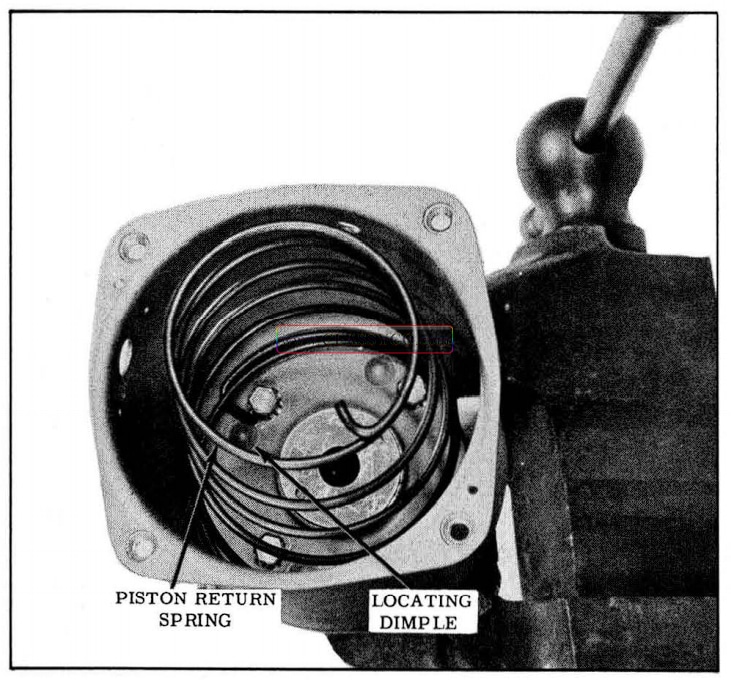
1957 Oldsmobile Installing Piston Return Spring
- Wipe lip of vacuum piston leather packing with light coating of shock absorber fluid.
- Install vacuum hose to vacuum piston assembly with Super Weatherstrip Adhesive.
- Position vacuum piston assembly on top of coil spring. (See Fig. 7 -39)
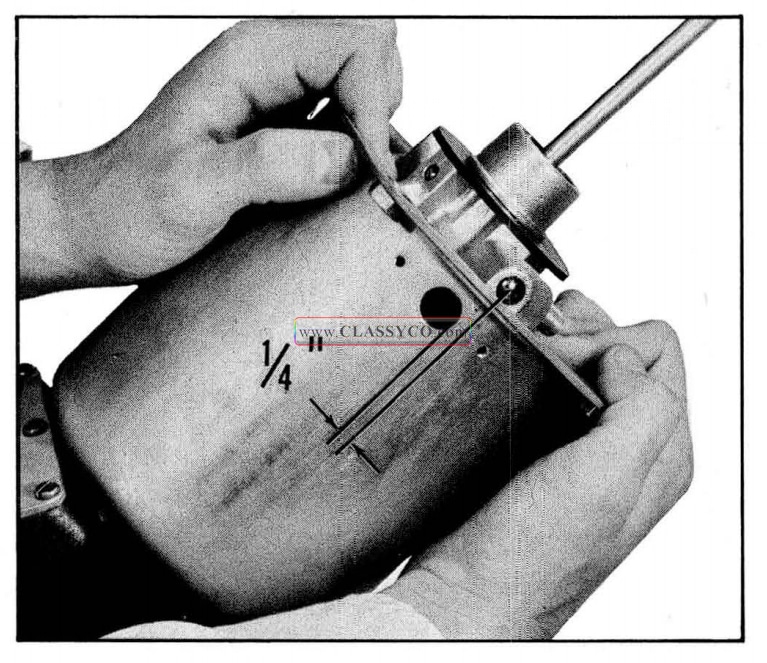
1957 Oldsmobile Vacuum Piston Alignment
- Depress vacuum piston assembly into housing and attach vacuum inlet tube and gasket.
- Slip hose onto inlet tube approximately 5/8″.
- With the vacuum piston back against vacuum inlet tube, make sure that rubber hose lays flat against piston and does not rub sides of power cylinder.
- Install power cylinder end plate and gasket.
- With the felt washer in the second large con volution of boot, install felt washer and dust boot over push rod and fit boot snugly over flange on end plate.
- Lay hairpin spring inside air cleaner cover and place new or clean filter element on top of hairpin spring. Place rubber gasket on filter element, depress spring and element so that the edges of the gasket can be fitted over the flanges of the air cleaner cover.
- Insert cover screw with aluminum gasket through air cleaner assembly and attach to top of power cylinder.
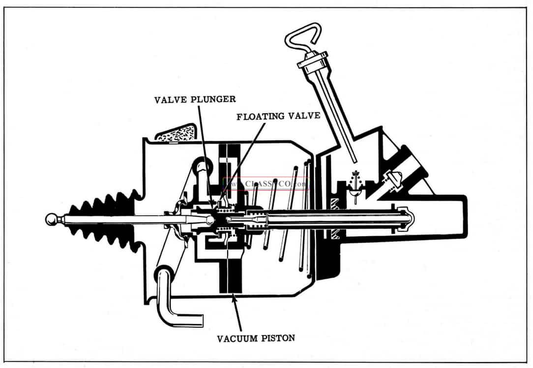
BENDIX POWER BRAKE
PRINCIPLES OF OPERATION
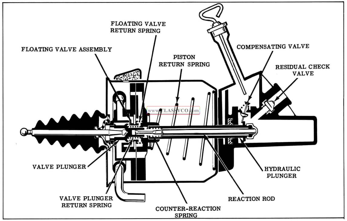
Released Position (Fig. 7-40)
In the released position, both sides of the vacuum piston are open to atmospheric pressure; therefore, the piston is balanced in atmospheric pressure and the vacuum piston is held in its released position by the piston return spring. This condition is accomplished by the following:
Vacuum is shut off within the piston since the floating valve assembly is held on its seat by the floating valve return spring. The valve plunger and push rod assembly is held in its released position away from the floating valve assembly by the valve plunger return spring. Atmospheric pressure, after passing through the air cleaner, enters the pow er cylinder at the rear side of the vacuum piston. It then passes through the vacuum piston to the valve plunger where it is admitted to the forward side of the vacuum piston.
The hydraulic plunger, being attached to the vacuum piston assembly, is held in the released position by the piston return spring. In this position, the compensating valve is held open and fluid can flow freely in either direction between the hydraulic cylinder and the fluid reservoir. Since there is no pressure build up in the hydraulic system, the reaction rod is held in its released position by the counter-reaction spring. The floating valve is held on its seat by the floating valve return spring, and the valve plunger is held away from its seat by the valve plunger return spring.
The fluid in the lines to the wheel cylinders is trapped by the residual check valve, thus maintaining pressure in the lines as in a conventional braking system.
1957 Oldsmobile Released Position (2)
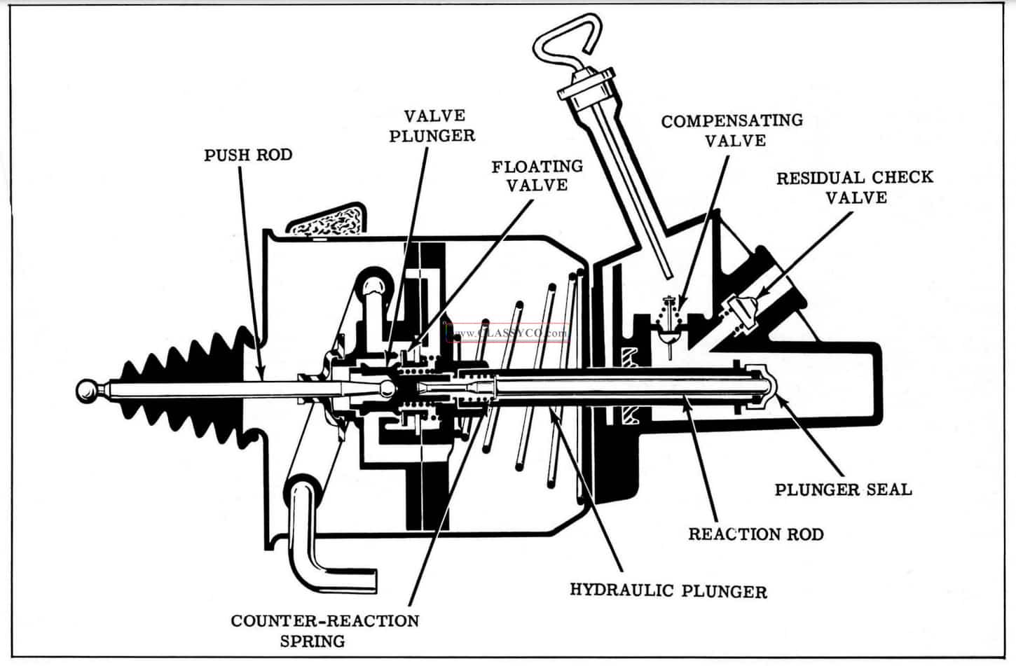
Applied Position (Fig. 7-41)
In the applied position, vacuum existing on the forward side of the vacuum piston and atmospheric pressure on the rear side of the vacuum piston overcomes the piston return spring and forces the vacuum piston in the applied position. This condition is accomplished by the following:
Atmospheric pressure is blocked off from the forward side of the vacuum piston as the valve plunger contacts the floating valve. Further movement of the valve plunger pushes the floating valve from its seat in the vacuum piston and permits vacuum to be communicated to the forward side of the vacuum piston. Atmospheric pressure on the rear side of the vacuum piston moves the piston and the hydraulic plunger in the applied direction.
The initial movement of the hydraulic plunger in the applied direction closes the compensating valve, sealing off the fluid reservoir from the hydraulic cylinder. Further movement of the plunger in the applied direction increases pressure in the master cylinder and forces fluid past the residual check valve and through the hydraulic lines into the wheel cylinders to apply the brakes. As fluid pressure increases in the master cylinder, a reaction force is transmitted to the reaction rod through the plunger seal to overcome the counter-reaction spring and move the valve plunger away from the floating valve. This allows the vacuum port to close and the atmospheric port to reopen which results in a reaction force which is in proportion to the fluid pressure in the master cylinder and the brake lines. Since the reaction force balances the force on the push rod by the driver, it provides the driver brake “feel”.
1957 Oldsmobile Applying Position (2)
Holding Position (Fig. 7-42)
When the desired brake application has been reached, the driver stops increasing the brake pedal force, which in turn holds the push rod and valve plunger stationary. The vacuum piston will continue to move forward as in the applied position until its seat rests against the floating valve. At this point, both the valve plunger and the floating valve are closed and no further movement of the vacuum piston takes place until the force on the pedal is either decreased or increased.
1957 Oldsmobile Holding Position (2)
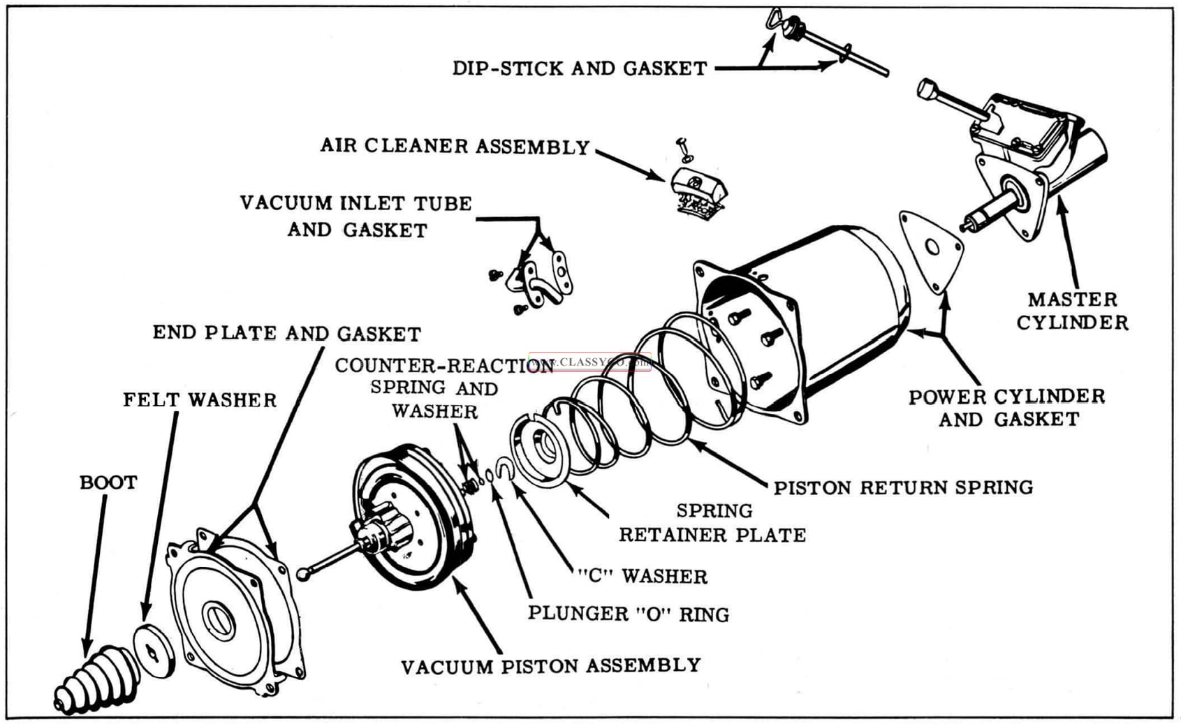
DISASSEMBLY OF BENDIX POWER BRAKE (Fig. 7-44)
NOTE: Use extreme care to keep mineral oil or gr ease from coming in contact with hydraulic parts.
- Clean all dirt from the outside of the power brake unit. Remove dipstick and gasket and empty brake fluid from master cylinder casting.
- Mount unit in Holding Fixture J -5433, if available. (See Fig. 7 -43) If holding fixture is not available, clamp cylinder end of unit in a vise.
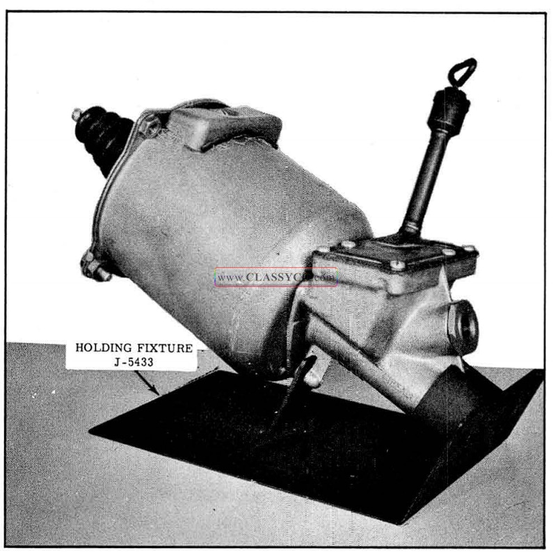
1957 Oldsmobile Power Brake Holding Fixture (2)
- Remove boot and felt washer. Bend tabs on end plate, then remove end plate and gasket.
- Remove the screw attaching air cleaner unit to power cylinder. Remove any burr inside of cylinder at air cleaner screw hole to prevent damage to the packing during piston removal.
- Slip rubber hose from vacuum inlet tube in side power cylinder, then remove the inlet tube and gasket. Remove any burr at inlet tube holes to prevent damage to the packing during piston removal. Pull vacuum piston from power cylinder. Remove counter-reaction spring from hydraulic plunger.
- R e move “O” ring from hydraulic plunger. Push in on spring retainer plate to free “C ” washer, then remove “C” washer, retainer plate, and vacuum piston return spring.
- Scribe alignment marks across power cylinder and master cylinder casting. Remove cap screws from the inside of the power cylinder, then remove the power cylinder and gasket.
1957 Oldsmobile Bendix Power Brake
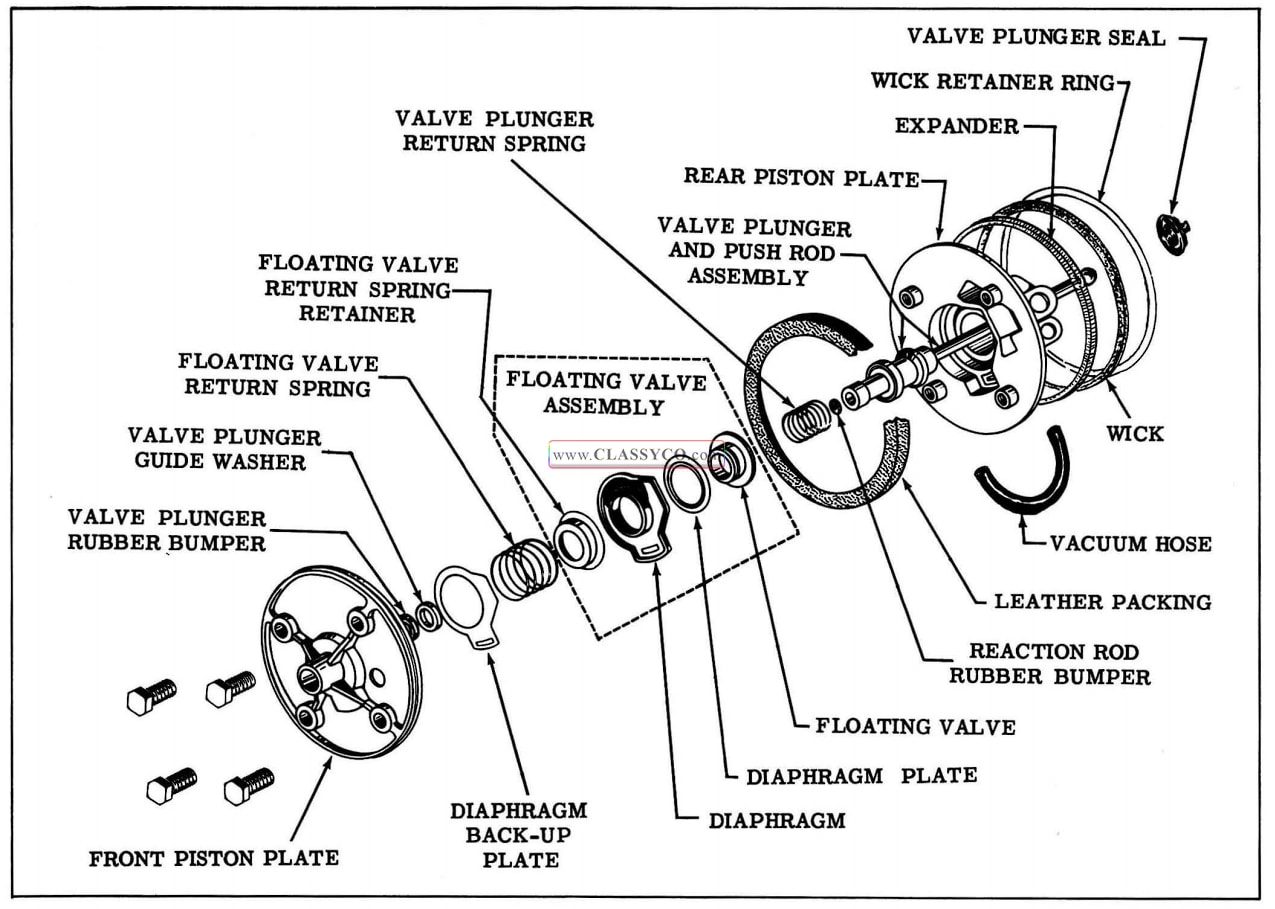
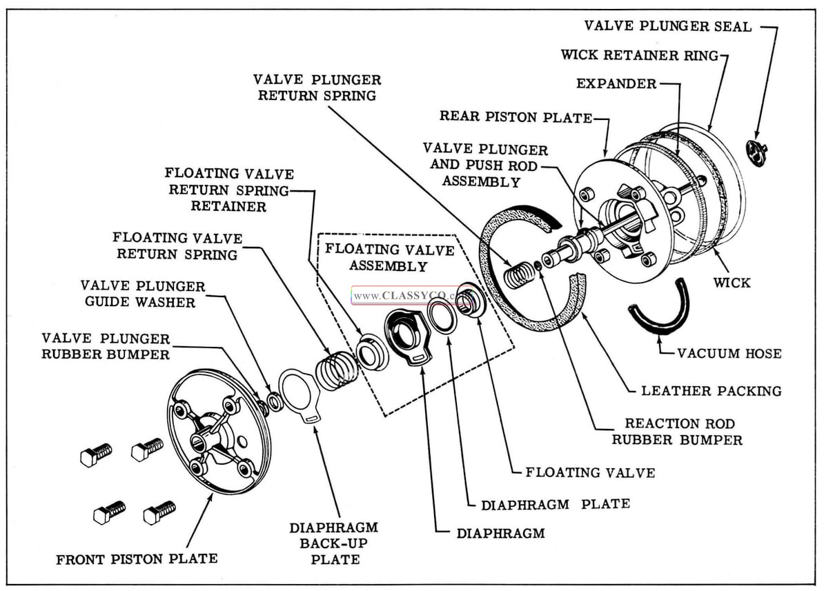
DISASSEMBLY OF VACUUM PISTON (Fig. 7-45)
- Remove the vacuum hose from the vacuum piston. Remove the valve plunger seal from the vacuum piston and push rod.
- Remove wick retainer ring, wick, and expander from rear piston plate.
- Turn piston over, clamp rear piston plate in vise, then remove the 4 cap screws.
- Remove the front piston plate, floating valve return spring, and valve plunger return spring.
- If necessary to remove the fiber valve plunger guide washer from front piston plate, remove the staking, then pry out the washer.
- Using a small hook wire, remove the valve plunger bumper from the front piston plate.
- Remove the diaphragm back-up plate, floating valve assembly, and leather packing from the rear piston plate.
- If necessary, disassemble the floating valve assembly.
- Remove valve plunger and push rod assembly from rear piston plate. If necessary to remove reaction rod bumper from inside small end of valve plunger, remove using a small wire hook.
1957 Oldsmobile Vacuum Piston Assembly (3)
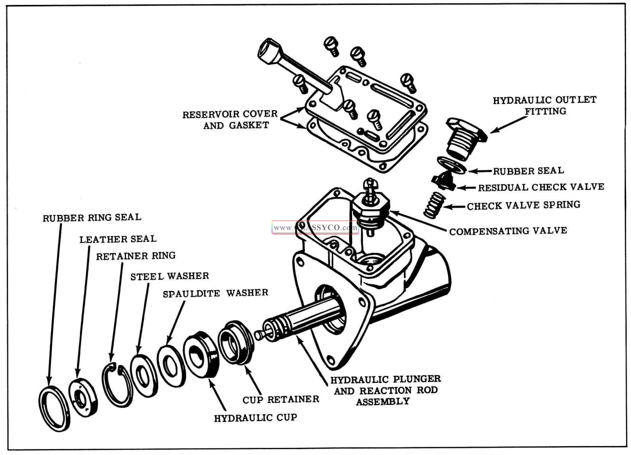
DISASSEMBLY OF MASTER CYLINDER (Fig. 7-46)
- Scribe alignment marks across master cylinder and reservoir cover, then remove cover and gasket.
- With a 1-1/8″ thin wall socket, remove compensating valve assembly.
- If necessary to disassemble compensating valve assembly, refer to Fig. 7-47.
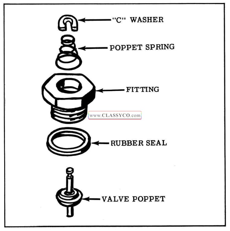
1957 Oldsmobile Compensating Valve
- Remove rubber ring seal from master cylinder bore.
- Push in on hydraulic plunger and then pull out to remove vacuum seal from recess in hydraulic cylinder.
- Using internal pliers, remove retainer ring from bore of hydraulic cylinder.
- Pull plunger out of master cylinder. Remove steel and fiber washers, rubber cup, and cup retainer from plunger.
- Remove the plunger seal and thin plastic washer from front end of plunger. The reaction rod and hydraulic plunger are serviced as an assembly and should not be disassembled.
- Remove hydraulic outlet fitting, residual check valve cup and retainer and check valve spring from master cylinder. Remove rubber seal from outlet fitting.
1957 Oldsmobile Master Cylinder (3)
CLEANING AND INSPECTION BENDIX POWER BRAKE
CLEANING
Thoroughly wash all parts in alcohol, blow out all passages, and air dry. Place clean parts on clean paper.
INSPECTION
In addition to parts contained. in repair kits, inspection of parts should be made as directed below, and parts replaced as necessary.
Power Cylinder
Inspect for scoring, pitting, dents or nicks, or damaged threads. Small imperfections may be smoothed out with fine crocus cloth.
Master Cylinder Casting
Examine bore one inch down from open end. For hydraulic cup to seal properly, this portion of bore must be free from scores, deep scratches, and corrosion. Gasket surfaces at reservoir cover, compensating port, and outlet fittings, must be free from scoring, pitting, dents, and nicked edges. Also check for cracks and damaged threads.
Hydraulic Outlet Fitting
Surface at small end of fitting must be free from scoring or corrosion which might prevent sealing with residual check valve rubber cup.
Compensating Valve Fitting
Surface at end of bore (inside threaded portion) must be free of scoring or corrosion which might prevent sealing with rubber poppet on compensating valve.
Vacuum Inlet Tube
Make sure braze is secure and tube plate is not distorted.
Hydraulic Plunger and Reaction Rod
Inspect plunger and reaction rod for scoring, pitting, or dents. DO NOT attempt to refinish plunger, as an undersize plunger may cause serious hydraulic leakage. The plunger and re action rod must be serviced as an assembly and cannot be disassembled.
Valve Plunger and Push Rod Assembly
Push rod must pivot freely in valve plunger with out noticeable end play. Replace the complete valve plunger and push rod assembly if damaged.
Vacuum Cylinder End Plate
Examine end plate for distortion.
Vacuum Piston Casting
Inspect vacuum piston valve plunger bore and valve seats for scratches and nicks.
ASSEMBLY OF MASTER CYLINDER (Fig. 7-46)
- Coat the outlet fitting rubber seal with brake fluid and assemble over hydraulic outlet fitting, then assemble the residual check valve and spring into fitting.
- Hold the master cylinder casting upside down and insert the residual check valve assembly and outlet fitting into check valve bore. Tighten to 50 ft. lbs.
- Install thin plastic washer and plunger seal on plunger. (See Fig. 7 -48) Apply a thin film of Dow Corning 4X compound on · the inside surface of the plunger seal, then assemble seal over end of plunger.
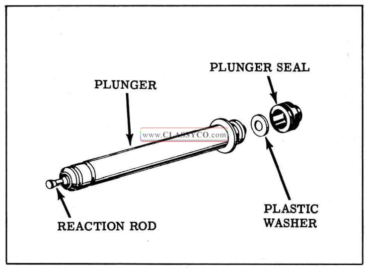
1957 Oldsmobile Reaction Rod and Plunger Assembly
- Insert the washer end of the hydraulic plunger into the master cylinder. Install the cup retainer on the plunger.
- Coat the hydraulic cup with brake fluid and install with cup lips against cup retainer. Install fiber washer, then steel washer on plunger. Install snap ring in the master cylinder bore with internal pliers.
- If the compensating valve was disassembled, assemble as shown in Fig. 7-49. Crimp “C” washer to retain in place.
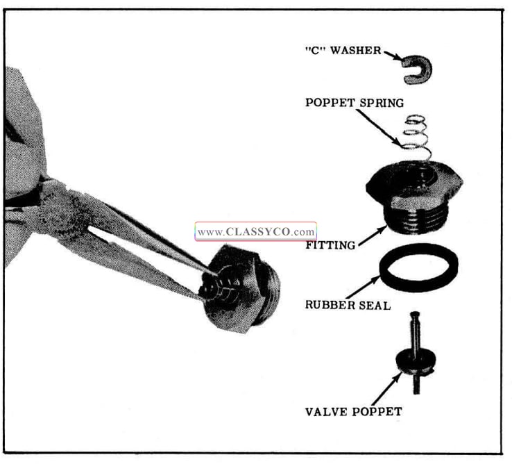
1957 Oldsmobile Compensating Valve Assembly
- Coat the compensating valve rubber seal with brake fluid. Push hydraulic plunger into master cylinder, then install compensating valve assembly in bore. Torque to 15 ft. lbs. Pull back on the plunger to be sure the plunger washer tilts the compensating valve.
- Install reservoir cover and new gasket. Note cover to reservoir casting alignment marks to insure filler tube is correctly located. Install dipstick and gasket.
- Install modified Seal Tool J-5405 (See Inset Fig. 7 -50) on the plunger, then slide the leather seal over the tool with the seal lip facing master cylinder and position seal into recess of master cylinder. Remove tool.
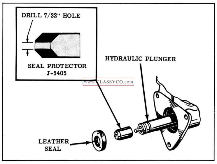
1957 Oldsmobile Installing Leather Seal
- Place rubber seal into master cylinder counterbore around leather seal.
- Install power cylinder and gasket on master cylinder casting. Note power cylinder to master cylinder alignment marks to insure that power cylinder is correctly located.
ASSEMBLY OF VACUUM PISTON (Fig. 7-51)
- If the reaction rod bumper was removed, install the bumper into bore of the valve plunger.
- Place rear piston plate in a vise so that the push rod is down, then install leather packing on piston plate with lip down.
- If the floating valve assembly was disassembled, assemble as follows: Assemble diaphragm plate in groove of diaphragm (See Fig. 7 -52) then snap floating valve into diaphragm. Assemble return spring retainer over floating valve.
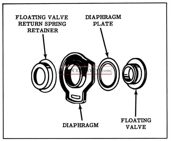
1957 Oldsmobile Floating Valve (2)
- Install the floating valve assembly in the rear piston plate, then install the diaphragm backup plate.
- Install the valve plunger return spring on the valve plunger.
- Install the valve plunger bumper in the front piston plate. If the fiber valve plunger guide was removed from the front piston plate, place the washer in the bore of plate and stake in four places.
- Install the floating valve return spring onto the front piston plate. Align hole of front piston plate with hole in rear piston plate cavity, then install the 4 cap screws finger tight.
- Place vacuum piston assembly in Ring J-5406. (See Fig. 7-53)
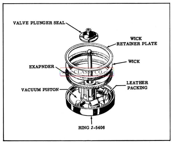
1957 Oldsmobile Piston Packing Assembly
- Place wick inside of expander, saturate wick with shock absorber fluid, then install wick and expander against leather packing (with fingers of expander up).
- Place wick retainer ring (dished side up) against felt wick and secure inner edge of retainer ring at the four notches in the rear piston plate.
- Tighten the 4 front piston to rear piston plate cap screws. Remove vacuum piston assembly from Ring J-5406.
- Dip the valve plunger seal in brake fluid, then install over push rod. Make sure seal is seated in groove of piston assembly.
- Install vacuum hose to vacuum piston.
1957 Oldsmobile Vacuum Piston Assembly (4)
VACUUM PISTON INSTALLATION (Fig. 7-54)
- Apply a thin film of shock absorber fluid to the inside of the power cylinder. Pull hydraulic plunger out, then place vacuum piston return spring in power cylinder with the large diameter of spring at the bottom.
- Place the retainer plate on the spring. Com press the spring and install the “C” washer in the groove of the plunger.
- Install new “O” ring on hydraulic plunger. Place washer and counter-reaction spring in hydraulic plunger.
- Install the vacuum piston assembly in the cylinder so that the free end of the hose is in line with the center of the elongated hole in the cylinder.
- Install the vacuum tube and gasket to the power cylinder and slip vacuum hose approximately 5/8″ onto vacuum tube.
- Operate piston by hand to make certain that the hose does not rub against the cylinder or piston. If interference occurs, rotate piston to a position where interference does not occur.
- Assemble air cleaner by installing filter element in air cleaner shell and place the rubber seal on the bottom edge of air cleaner shell. Install air cleaner to power cylinder.
- Align end plate and gasket to power cylinder and bend tabs of end plate to secure plate and gasket to cylinder.
- Assemble felt washer into second large con volution of rubber boot. Install boot over push rod and attach to “scallops” of end plate.
1957 Oldsmobile Bendix Power Brake (2)
POWER BRAKE TESTING
Any time a power brake unit has been removed and replaced, or a new unit installed on a car, vacuum and hydraulic leakage tests as well as operational tests should be made to determine whether the unit is operating up to standard.
Road test the brakes by making a brake application at about 20 m.p.h. to determine if the vehicle stops evenly and quickly. If the pedal has a spongy feel when applying the brakes, air is present in the hydraulic system. Bleed the system at each wheel cylinder.
With the engine stopped and the transmission iii neutral, apply the brake several times to exhaust all vacuum in the system. Depress the brake pedal, hold foot pressure on the pedal, and start the engine. If the vacuum system is operating, the pedal will tend to fall away under foot pressure, and less pressure will be required to hold the pedal in the applied position. If no action is felt, the vacuum system is not functioning.
Stop the engine and again exhaust all vacuum in the system. Without starting the engine, de press the brake pedal and hold foot pressure on the pedal. If the pedal gradually falls away under foot pressure, the hydraulic system is leaking.
If the brake pedal travels to within 1 inch of the toe board, the brake shoes require readjustment or relining.
A faulty vacuum check valve may be tested by shutting off the engine and, after waiting a few minutes, applying the brakes; there should be sufficient vacuum reserve for several applications.
BRAKE DIAGNOSIS
The following diagnosis applies to both power brakes and standard brakes unless otherwise specified.
Brake troubles may be easily diagnosed if the complaint is understood. The trouble will always show up in one or more of the four ways listed below. Related parts of the power brake or standard brake system should be checked before dis mantling the brake when a malfunctioning brake system is encountered.
- Hard Pedal Feel May be Caused By:
A. Power brake vacuum failure due to:
a. Faulty vacuum check valve.
b. Collapsed vacuum hose.
c. Plugged or loose vacuum hose or fittings.
d. Leaking vacuum reservoir tank.
B. Bound up pedal mechanism.
C. Glazed linings.
D. Grease on brake drum or linings.
E. Power brake unit trouble due to:
a. Internal vacuum hose loose or restricted.
b. Vacuum leak in vacuum piston assembly or past leather piston packing.
c. Leak at power cylinder to master cylinder mounting face.
d. Faulty vacuum seal (Moraine).
e. Restricted air cleaner.
f. Jammed push rod valve plunger (Bendix).
g. Jammed air valve (Moraine).
h. Broken counter -reaction spring (Bendix).
i. Leak past floating valve.
2. “Grabby” or sever brakes caused by:
A. Grease or brake fluid on linings.
B. Scored drums.
C. Anchor pins improperly adjusted (new linings).
D. Power brake unit trouble due to:
a. Sticking push rod valve plunger or air valve.
b. Master cylinder plunger binding in vacuum piston guide. (Moraine).
c. Binding reaction rod in hydraulic plunger (Bendix).
3. Pedal goes to floor (or almost to floor) caused by:
A. Brakes require adjustment.
B. Air in hydraulic system.
C. Hydraulic leak in lines or at wheel cylinders.
D. Fluid reservoir needs replenishing.
E. Cracked drums.
F. Power brake hydraulic leakage at:
a. Compensating valve or seal.
b. Hydraulic plunger seals.
c. Outlet fitting.
d. Sand hole or crack in master cylinder.
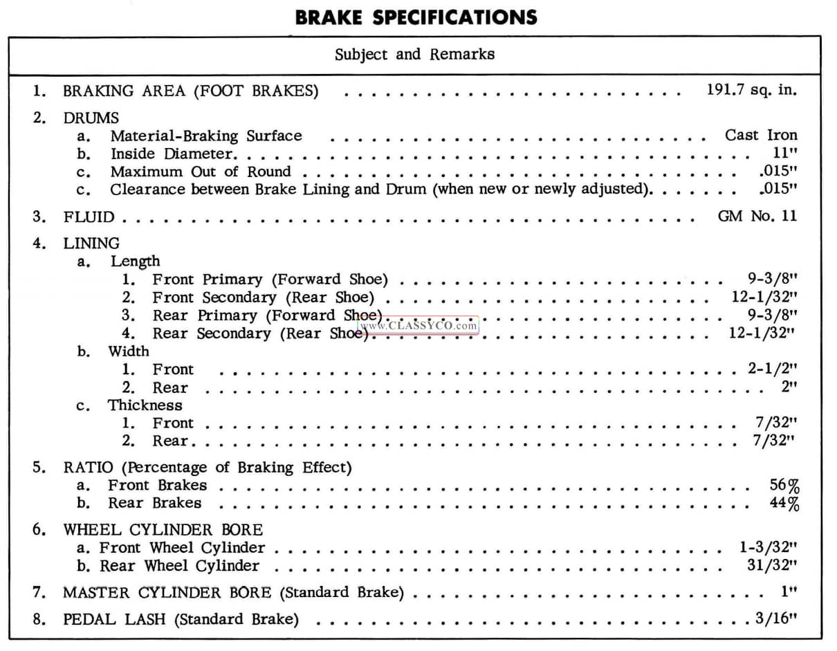
1957 Oldsmobile Brake Specifications
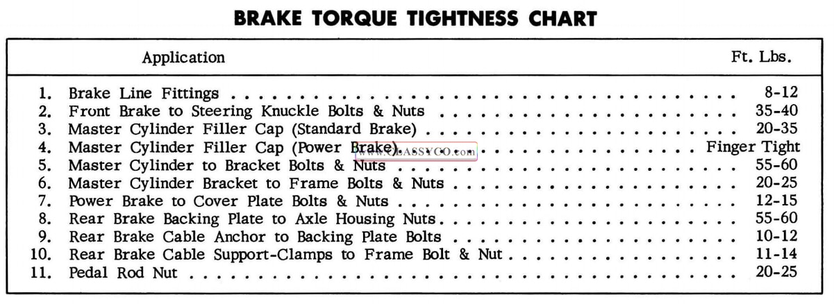
1957 Oldsmobile Brake Torque Tightness Chart
1957 Oldsmobile 88 Convertible Coupe (CR)