REAR SUSPENSION
REAR SPRINGS
REMOVE AND REPLACE
- Hoist rear of car.
- Disconnect shock absorber from rear spring “U” bolt plate.
- Remove “U” bolts, insulators, and spring “U” bolt plate.
- Use jack to raise axle housing slightly off spring, then remove rear spring shackle bolts. (See Fig. 6-1)

1957 Oldsmobile Removing Spring Shackle Bolt
- Disconnect front of spring from front hanger by removing the front spring nut and bolt, then remove spring.
IMPORTANT: The left and right rear springs are NOT interchangeable. The spring can be identified by the pan number stamped on the top of the spring clip retainer.
To replace spring, reverse sequence of operations. A soap solution may be applied to rubber bushings to aid installation. When replacing spring, insert only the outer rubber bushing in the front spring eye before placing spring in hanger. The inner rubber bushing can be inserted into the spring eye through the hole in the front spring hanger after the spring is in place. (See Fig. 6-2)
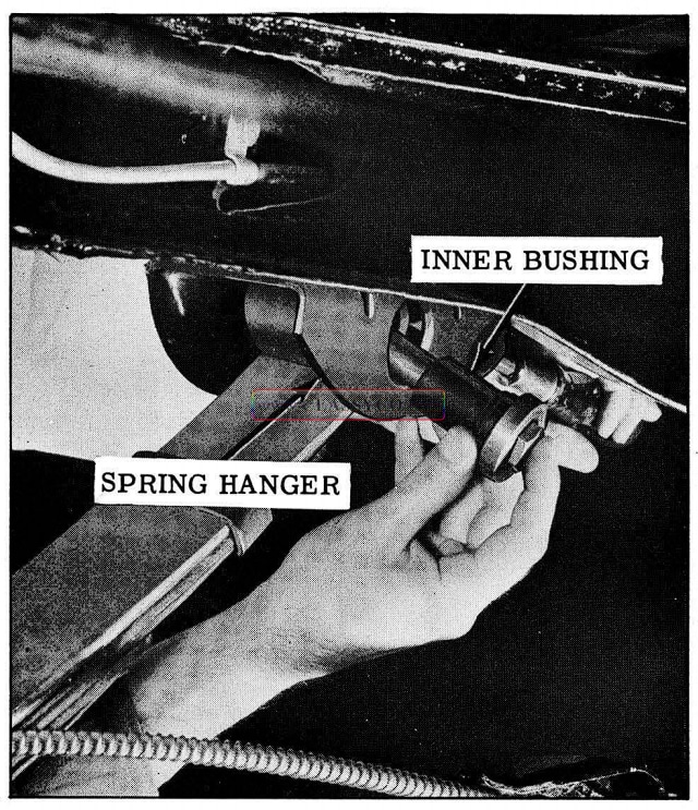
1957 Oldsmobile Installing Rear Spring Front Bolt
Torque rear spring axle “U” bolt nuts 50 to 55 ft. lbs. Allow weight of car to rest on springs before tightening nuts on spring shackle and front eye bolts 75 to 85 ft. lbs.
REAR SHOCK ABSORBER
Rubber insulated double action shock absorbers are of the direct acting type. If found to be leaking or improperly operating, the complete shock absorber assembly should be replaced.
Checking Operation
Disconnect lower end of both shock absorbers. By operating a shock absorber with each hand, work the shocks up and down. The movement of the shocks should be smooth and it should require equal force to operate both shock absorbers.
NOTE: If the operation of the shocks is erratic or unequal, it is due to a malfunction of one or both of the units and will require replacement. In order to obtain proper riding characteristics, the shocks must operate smoothly and at equal loads.
Remove and Replace
- Remove shock absorber lower mounting nut at spring “U” bolt plate.
NOTE: To disengage shock absorber stud from the spring seat, hammer on the spring “U” bolt plate adjacent to the stud.
- Remove shock absorber upper pivot bolt from frame and remove shock absorber.
NOTE: The upper and lower bushings are integral with the shock absorber and no serv ice is required other than shock absorber replacement.
To install, loose-assemble shock absorber at both ends before tightening the mounting nuts and bolt. Torque lower stud nut 35 to 45 ft. lbs. and the upper bolt and nut 65 to 75 ft. lbs. Shock absorbers do not require lubrication.
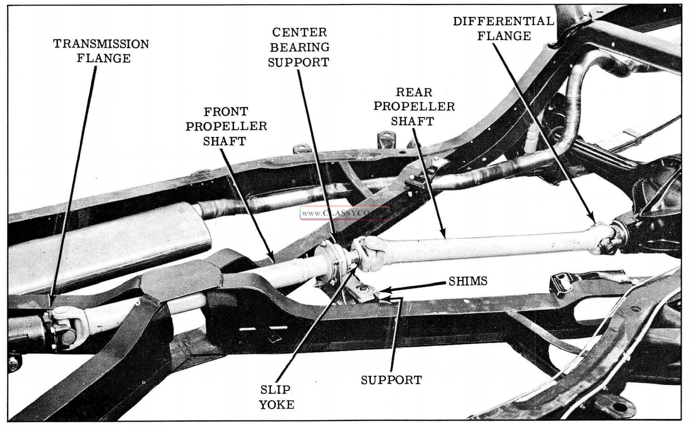
PROPELLER SHAFT ASSEMBLY (Fig. 6-3)
The 1957 propeller shaft assembly consists of two sections, the front propeller shaft which ex tends from the transmission flange to a permanently lubricated bearing supported by a rubber insulated support and the rear propeller shaft which extends from the center bearing support assembly to the differential flange. The front and rear propeller shafts are connected to each other by a slip yoke. The rear propeller shaft or the support can be removed independently of the front propeller shaft and center bearing. Whenever it is necessary to remove the front shaft or center bearing, the complete propeller shaft assembly should be removed as an assembly. The propeller shaft assembly is a balanced unit and should be kept free of undercoating or other material which may upset the balance.
Oldsmobile uses both Saginaw and Spicer propeller shaft assemblies. Saginaw assemblies can be identified by the “C” shaped ”U” joint bearing snap rings located adjacent to the inner sides of the yokes, whereas Spicer assemblies use a “D” shaped ”U” joint bearing snap ring which fits into the outer edge of the yokes.
1957 Oldsmobile Propeller Shaft Assembly
PROPELLER SHAFT ALIGNMENT
Vertical Alignment
- Position Aligning Gauge 6514 against right side flange of transmission oil pan (Hydra-Matic) or right side of engine oil pan (Syncro-Mesh so the contact surfaces of the gauge seat squarely against the pan with level adjusting screw toward front of car. (See Fig. 6-4)
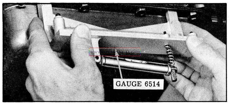
1957 Oldsmobile Positioning Gauge 6514 Against Pan
- Adjust the leveling screw until bubble is centered in the gauge level.
- Position the gauge against the front propeller shaft so the contact surfaces of the gauge seat squarely against the bottom and side of the propeller shaft with level adjusting screw toward front of car. (See Fig. 6-5)
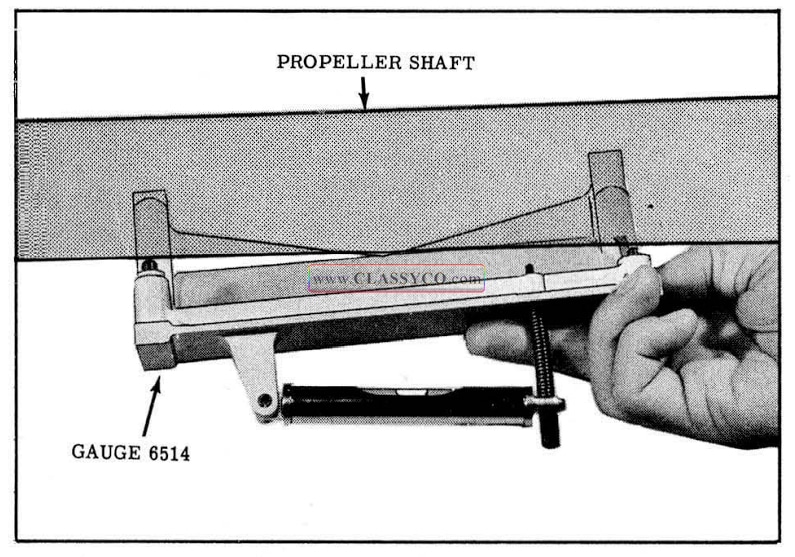
1957 Oldsmobile Positioning Gauge on Front Propeller Shaft
- If the bubble is not within 1/16″ from the center of the level; it will be necessary to align the front propeller shaft as follows:
a. Scribe a line from the center of the support to frame member attaching bolts on the frame member to facilitate lateral alignment on reassembly.
b. Add or subtract shims between the frame member and the support as required (refer to shim chart) until bubble in gauge level is centered (or within ± 1/16″ from center of level).
NOTE: Install shims with bent end down.
1957 Oldsmobile Table Shim Sizes
c. Align support to frame member attaching bolts and torque 45 to 55 ft. lbs. Recheck vertical alignment.
Lateral Alignment
- Attach three plumb lines using string 18″ to 24″ long to the under side of the car in such a position that the strings touch the side of the propeller shaft. Position one string at the front of the front propeller shaft, between the front weld and balance weights. Put the second string at the rear of the front shaft ahead of the center bearing, between the end weld and balance weights, and the third plumb line at the rear of the rear shaft in a similar position.
- Sight along the three plumb lines. If the center line does not line up with the front and rear strings, loosen the support to frame member bolts and slide the center bearing assembly laterally in the elongated holes of the frame member until alignment is obtained. Torque bolts 45 to 55 ft. lbs.
REAR PROPELLER SHAFT OR SLIP YOKE SEAL
Removal
- Pry crimped area of slip yoke nut retainer away from nut, then unscrew nut until it is free of threads. (See Fig. 6-6)
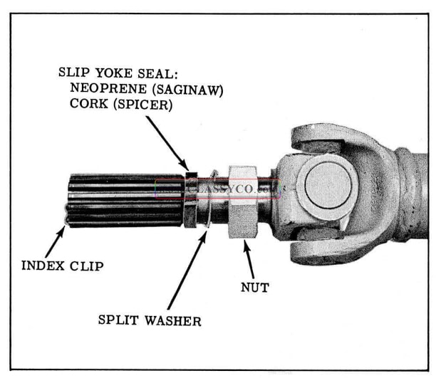
1957 Oldsmobile Slip Yoke
- Remove “U” bolts from differential companion flange.
- Use a piece of soft wire or a rubber band to retain bearings on spider journals to prevent loss of bearing assemblies.
NOTE: This operation will not be necessary if the flat bearing retainer strap has not been cut.
- Remove the propeller shaft from the car, then remove the nut retainer and rear slinger.
NOTE: The nut retainer and rear slinger may remain on the front propeller shaft or come off with the slip yoke.
- If necessary, remove slip yoke seal.
Replacement
- Install new slip yoke seal if it was removed.
- Apply one ounce of special lubricant (Part No. 571035) to the splines of the front propeller shaft.
- Place rear slinger against center bearing on the front propeller shaft with the dished side rearward.
- Place nut retainer on the front propeller shaft with the tang in the slot and the cupped side facing rearward.
- Align slip yoke index clip with wide serration in front propeller shaft and install slip yoke.
- Using a 4 inch “C” clamp compress bearings that attach to companion flange. This will allow clearance for bearing snap rings when installing propeller shaft to companion flange. Align “U” joint bearing flat wire retainer with relieved area in companion flange. Connect propeller shaft to flange. Torque “U” bolt nuts 18 to 22 ft. lbs. and bend lock plate to retain nuts. Remove “C” clamp.
- Tighten slip yoke nut approximately 30 ft. lbs. Crimp the nut retainer against the nut.
PROPELLER SHAFT (FRONT AND REAR) AND CENTER BEARING SUPPORT ASSEMBLY
Removal
- Scribe a vertical line on the center of the sup port and on the frame member to facilitate lateral alignment on reassembly.
- Remove center bearing support bolts and shims from frame member.
NOTE: Keep shims grouped so they can be reinstalled in their same location.
- Remove “U” bolts from companion flanges at the transmission and differential.
- Use a piece of soft wire or a rubber band to retain bearings on spider journals to prevent loss of bearing assemblies.
NOTE: This operation will not be necessary if the flat retainer has not been cut.
- Remove complete assembly by sliding it rearward out of frame.
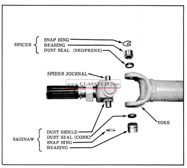
Universal Joints (Fig. 6-7)
With the propeller shaft assembly removed from the car remove the bearings that are assembled into a yoke as follows:
- Remove snap rings that retain the bearings in the yoke.
NOTE: Saginaw snap rings are “C” shaped and fit over the bearing on the inner side of the yoke. Spicer snap rings are “D” shaped and fit into the outer edge of the yoke, on top of the bearing.
- Using a bronze drift, drive on the spider to force one bearing far enough out of the yoke so the bearing can be gripped in a vise.
- Clamp the exposed bearing in a soft jawed vise, then drive on the propeller shaft to pull the bearing from the yoke.
NOTE: The use of Tool J-4174 will facilitate the removal of Saginaw bearings.
- Repeat steps 2 and 3 on opposite bearing.
- Remove dust seals from spider.
- Remove spider from yoke.
NOTE: On Saginaw units, it will be necessary to remove one dust shield to obtain sufficient clearance for yoke removal.
To remove bearings that attach to a companion flange, cut the retaining strap between the bearings.
When a universal joint is disassembled, all parts should be thoroughly washed with gasoline and before the joint is reassembled, the reservoir in each journal PACKED with high melting point wheel bearing grease (fine fiber, sodium base) until the reservoir is COMPLETELY FILLED.
New dust seals should be used at each bearing assembly when reassembling the joint. The bearings may then be pressed in the yoke and over journals. After the bearings are pressed into position, in stall new snap rings.
1957 Oldsmobile Universal Joint
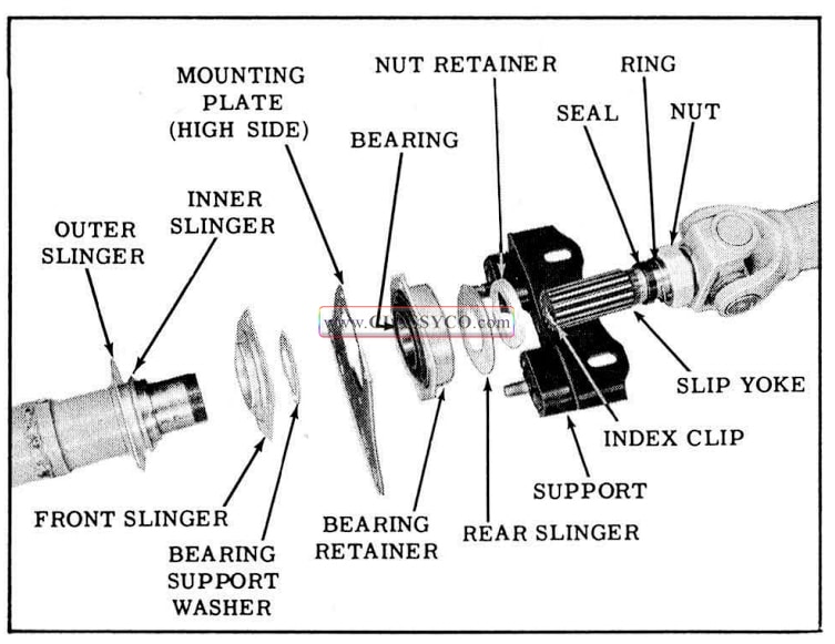
Center Bearing Support Assembly (Fig. 6-8)
To disassemble the center bearing support assembly, (bearing retainer, bearing, mounting plate, bearing support washer, and front slinger) or remove the assembly from the front propeller shaft, proceed as follows:
- With the propeller shaft assembly removed from the car, pry crimped area of slip yoke nut retainer away from nut, then unscrew nut until it is free of threads.
- Pull rear propeller shaft from front propeller shaft. Remove nut retainer and rear slinger.
- Remove the center bearing support assembly using Puller TR-278-R and Adapter TR-278- R-2 as shown in Fig. 6-9.
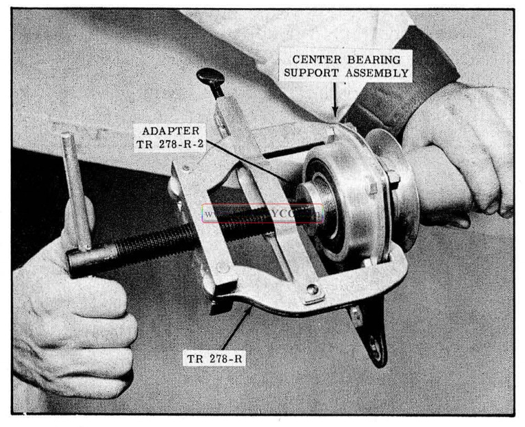
1957 Oldsmobile Center Bearing Support Removal
- If necessary to replace the bearing and bearing retainer, remove the bearing retainer to mounting plate bolts then separate the parts.
To assemble the center bearing support assembly, proceed as follows:
- Using new parts as necessary, assemble the center bearing support assembly as shown in Fig. 6-8. Torque bearing retainer to mounting plate bolts 14 to 17ft. lbs.
IMPORTANT: Apply a bead of No. 4 cup grease around the dished area of the front slinger and Permatex #2 between the bearing retainer and the mounting plate. This will pre vent foreign material from entering the bearing.
NOTE: The high side of the mounting plate should be on the right side and the bearing retainer should face rearward when installed in the car.
- With the center bearing support assembly placed over the front propeller shaft, install and tighten the slip yoke nut to force the assembly onto place. Remove slip yoke nut.
- Apply one ounce of special lubricant (Part No. 571035) to the splines of the front propeller shaft.
- Place rear slinger against center bearing on the front propeller shaft with the dished side facing rearward.
- Place nut retainer on the front propeller shaft with the tang in the slot and the cupped side facing rearward.
- Align slip yoke index clip with wide serration in the front propeller shaft and install slip yoke.
- Tighten slip yoke nut approximately 30 ft. lbs. Crimp the nut retainer against the nut.
1957 Oldsmobile Center Bearing Support Assembly
PROPELLER SHAFT (FRONT AND REAR) AND CENTER BEARING SUPPORT ASSEMBLY
Installation
- Use a 4 inch “C” clamp to hold the bearings against spider journals to obtain clearance of the bearing snap rings when installing propeller shaft to companion flanges.
- Position propeller shaft assembly on the car and loose assemble “U” bolts to transmission and differential companion flanges. Remove “C” clamps and torque ”U” bolt nuts 18 to 22 ft. lbs., then bend lock tangs against nuts.
NOTE: The bearing retainer must be centered in the relieved area of the transmission and differential flanges.
- With the original shims placed between the support and frame member, align scribe lines on support and frame member. Torque 45 to 55 ft. lbs.
- Check vertical and lateral alignment of the center bearing support assembly. (See PRO PELLER SHAFT ALIGNMENT)
AXLE SHAFT
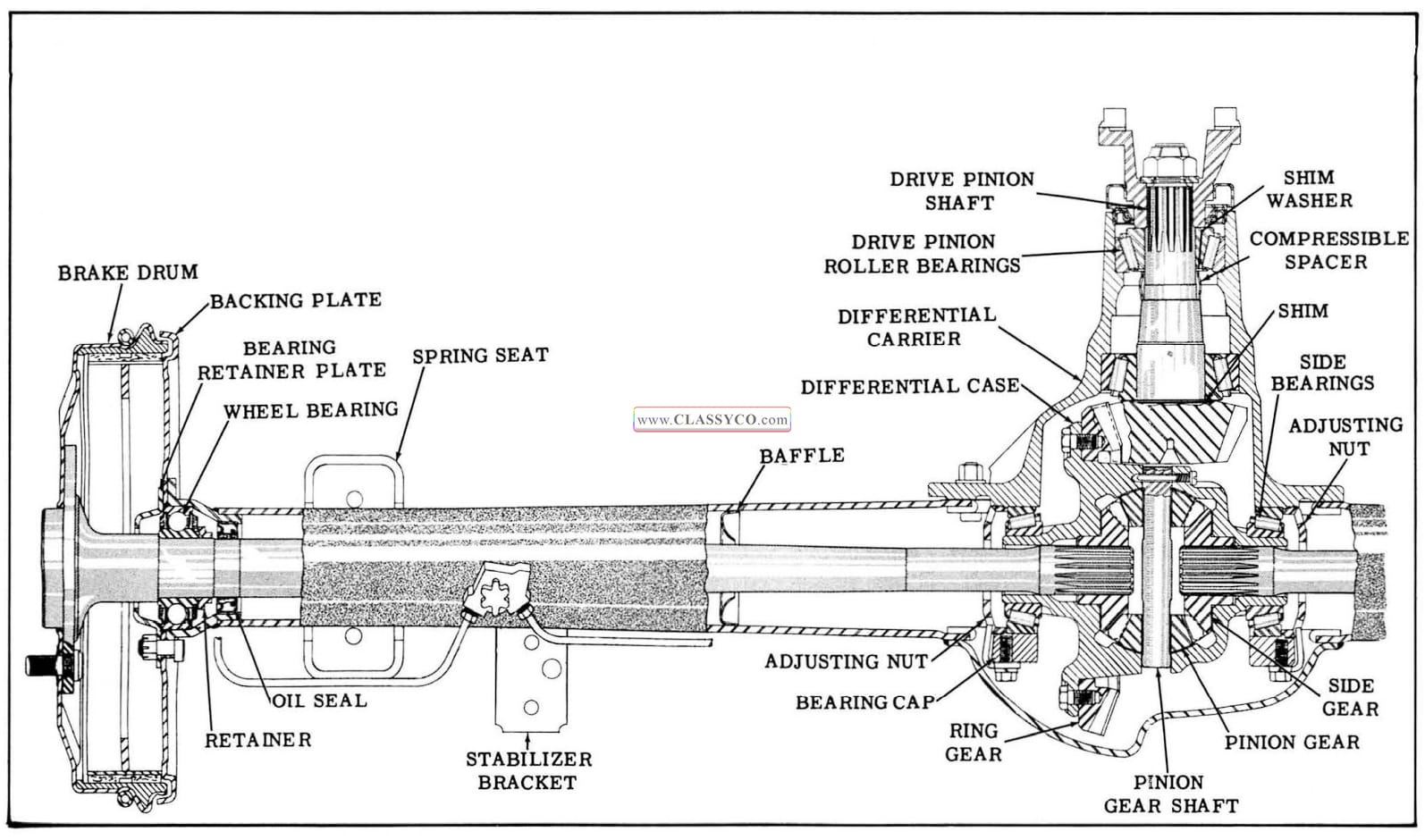
1957 Oldsmobile Rear Axle Assembly
Remove
- Remove wheel.
NOTE: Wheel nuts on left side of car, have left hand threads.
- Remove the two Tinnerman nuts from wheel studs which hold the brake drum in place and remove the drum.
NOTE: If Tinnerman nuts are removed by turning off threads, they can be reused; however, if nuts are damaged in any way they should be replaced.
- Remove nuts from the four bolts attaching brake backing plate to axle housing.
- Pull axle shaft bearing retainer plate away from backing plate, taking care not to dis lodge backing plate as brake line may be damaged.
- Pull axle shaft and bearing assembly from housing. Use Tool J -942 if bearing is a tight press fit in the axle housing. (See Fig. 6-11)
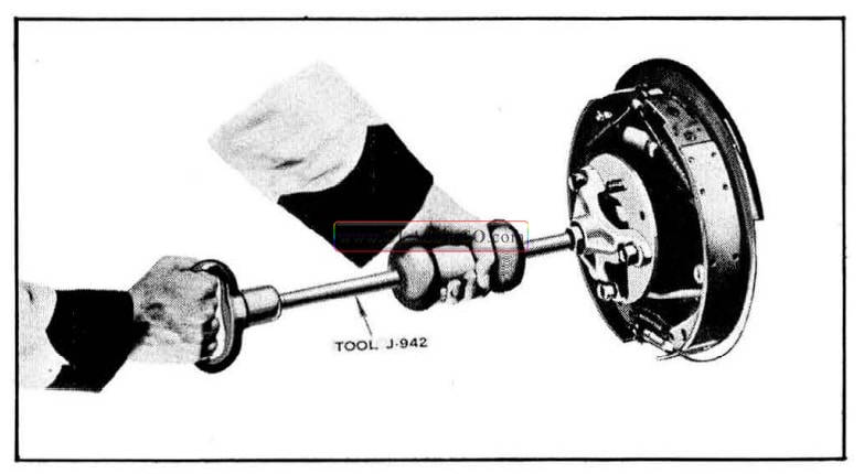
1957 Oldsmobile Removing Axle Shaft
NOTE: Extreme care must be exercised to prevent the axle shafts from dragging on oil seal. Bearings should be covered with a clean cloth to prevent dirt getting into bearings.
- Replace one backing plate attaching nut to hold plate in position.
Axle Shaft Bearing
The sealed rear wheel bearings are built with .012″ to.015″ end-play between balls and races and should not be rejected unless end-play is greater than .020 ” or definite roughness between ball and race can be felt when bearing is rotated by hand. The bearing should be checked for end play and roughness before it is removed from the axle shaft because if bearing has been removed from the axle shaft it cannot be used again.
NOTE: Tipping of either race can cause a large error in end-play reading.
Bearing Removal and Replacement
- With axle shaft removed, remove bearing retainer collar after splitting with cold chisel as shown in Fig. 6-12. Do not damage axle shaft.
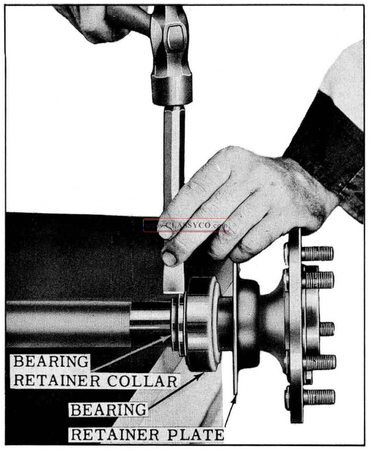
1957 Oldsmobile Removing Bearing Retainer
- Engaging outer race of bearing with Tool J-947-2, used in conjunction with J-947 -1, press off bearing in arbor press. (See Fig. 6-13) Remove bearing only when a new bearing is to be installed. (Tool J-947-2 is used during removal to prevent breakage of the bearing outer race which could result in personal injury.)
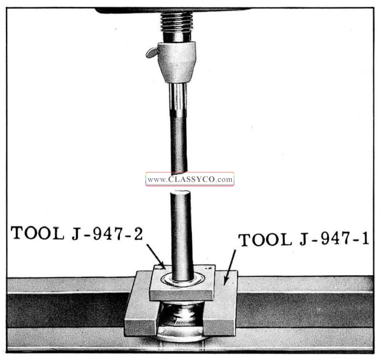
1957 Oldsmobile Removing Axle Shaft Bearing
- Using Tool J-947-3 in conjunction with plate J-947-1 press bearing over axle shaft, being sure that pressure is applied to inner race of bearing. After bearing has been pressed firmly against axle shaft shoulder, press new bearing retainer collar toward bearing. (See Fig. 6-14) Do not damage shaft surf ace on which oil seal will run.
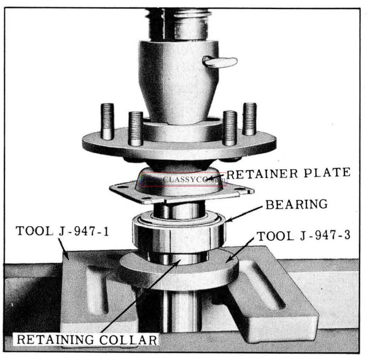
1957 Oldsmobile Installing Axle Shaft Bearing Retainer
Axle Shaft Replace
NOTE: Before replacing axle shafts examine oil seals. The oil seal has feather edges which form a tight seal around the axle shaft. If these feather edges are damaged in any way, oil will leak past the seal. Furthermore, if the seal is not properly installed in the axle housing, a leak is likely to occur around its outside diameter. When installing an oil seal apply sealer around its out side diameter, then install seal using Tool J-5818. (See Fig. 6-15)
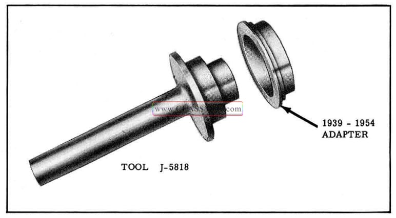
1957 Oldsmobile Axle Shaft Seal Installer
Before installing axle shaft examine the surface of the shaft on which the seal wipes to make sure that it is smooth and free from tool marks. If necessary, dress down shaft with crocus cloth.
If roughness or excessive play is detected in wheel bearing it will need to be replaced. (See AXLE SHAFT BEARING)
Axle shafts are serviced with wheel studs pressed into the flange of the shaft. The threads of these studs are left hand for the left hand side of the car and right hand for the right hand side of the car, thereby making the right and left hand shaft assemblies different for service.
- Remove temporary nut holding backing plate to axle housing.
- Clean inner surface of backing plate and place new gasket over backing plate mounting studs. Clean gasket side of retainer plate.
- Slide axle shaft and bearing assembly into place. EXTREME CARE MUST BE EXER CISED WHEN SLIDING THE AXLE SHAFT THROUGH THE OIL SEAL TO AVOID DAMAGING THE SEAL.
- Place retainer plate over backing plate mounting studs and install self-locking nuts Torque 55 to 60 ft. lbs.
- Replace brake drum and wheel assembly.
DIFFERENTIAL
PINION OIL SEAL REPLACEMENT
- Disconnect propeller shaft from differential companion flange and support shaft up in body tunnel.
- Mark the position of the companion flange, pinion shaft and nut so that they can be rein stalled in the same position.
- Remove companion flange nut, using Tool 6544 to hold flange. Remove washer.
- Remove companion flange using puller 6295-01. (See Fig. 6-16)
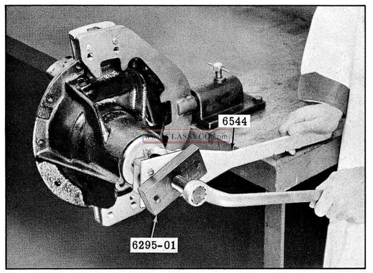
1957 Oldsmobile Removing Companion Flange
- Remove oil seal by driving it out of carrier with a blunt chisel.
- Examine surface of companion flange for tool marks, nicks, or damaged surface. If damaged, replace flange as per instructions under REPLACEMENT OF COMPANION FLANGE.
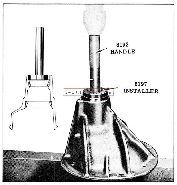
- Coat sparingly outside diameter of new seal with Permatex No. 2 and install seal using driver J-5395 to properly locate seal in carrier. (See Fig. 6-17)
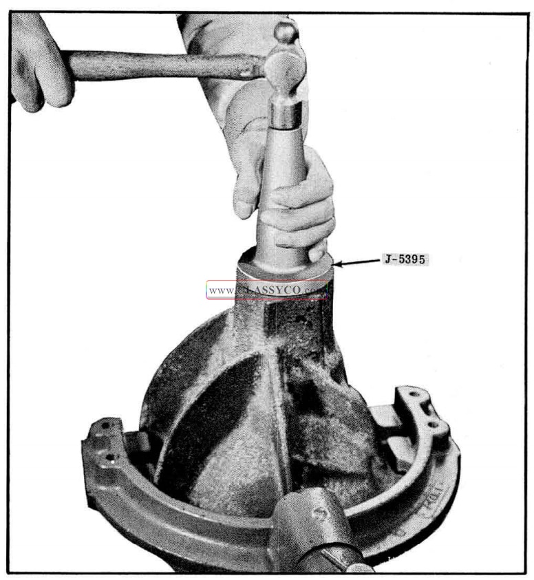
1957 Oldsmobile Installing Pinion Oil Seal
- Apply special seal lubricant (Part No. 567196) to the O.D. of the companion flange and the sealing lip of new seal.
- Install companion flange and tighten nut to the same position as marked in step 2 above, while holding companion flange with Tool 6544, then tighten nut 1/16″ beyond alignment marks.
COMPANION FLANGE REPLACEMENT
- Remove both rear wheels and brake drums.
- Remove both axle shafts BEING CAREFUL NOT TO DRAG THE AXLE SHAFT ACROSS THE SEAL.
- Disconnect rear universal joint and support propeller shaft up in body tunnel.
- Remove companion flange nut using holding Tool 6544.
- Remove washer and then remove companion flange using puller 6295-01. (See Fig. 6-17)
- Apply special seal lubricant (Part No. 567196) to the O.D. of the new companion flange, then install companion flange, washer, and companion flange nut finger tight.
- While holding companion flange with Tool 6544 and using a 1-1/4″ socket wrench, tighten the nut a little at a time and tum pinion several revolutions after each tightening to seat the rollers, checking the pre-load friction of bearings each time with an inch pound torque wrench or with spring scale J-544-A until pre-load is 10 to 15 inch pounds. (See DIFFERENTIAL DISASSEMBLY, Step 9)
NOTE: In no case should the bearing pre-load exceed 25 inch pounds if the differential has been in use.
- Connect rear universal joint.
- Install axle shafts carefully to avoid dragging shafts across seals.
- Install drums and wheels.
DIFFERENTIAL, REMOVE
- Remove the axle shafts.
- Clean the differential carrier and the axle housing around carrier to prevent dirt from entering the housing or falling on the gears.
- Remove the companion flange ”U” bolts. If “U” joint bearings are not retained by a retainer strap wire, use a piece of soft wire or masking tape to hold “U” joint bearing on spider. Support the propeller shaft up in the body tunnel.
- Drain the oil by removing nuts from carrier mounting studs and moving carrier away from axle housing.
CAUTION: Do not clean the differential until it has been disassembled. This will avoid washing dirt into the bearings.
DIFFERENTIAL, INSTALL
IMPORTANT: Differential gears that have failed or bearings that are damaged by chipping are certain to leave particles of metal in the housing. These particles of foreign material must be thoroughly cleaned from the housing before in stalling the carrier to prevent repeat failure.
Bearings that are not chipped, but are loose (lapped-in) are an indication of dust, grit, or dirt in the oil that caused the bearings to fail. This too must be thoroughly cleaned from the housing before installing the differential to prevent repeat failure of the bearings.
To assure that the housing is clean, thoroughly wash the interior of the housing with clean solvent. Loosen any particles that may be lodged by tapping the housing its entire length, then wipe the inside of housing dry to remove all metal particles.
- Clean the gasket surface on housing and install a new gasket.
- Install carrier over studs and carefully align the differential assembly with the housing so that both pedestal caps enter the supports in housing. Apply Permatex No. 2 on the stud threads, then install nuts on studs and tighten equally to draw carrier pedestal caps evenly into support in housing.
- Tighten nuts 50 to 60 ft. lbs.
- Install axle shafts, brake drums, wheels and rear propeller shaft.
- With car level, fill the rear axle housing to filler plug level. If new gears were installed, use EXTREME PRESSURE lubricant furnished with new gears; otherwise, use SAE 90 MultiPurpose Hypoid lubricant.
CAUTION: If new gears and/or bearings are installed, DO NOT DRIVE CAR OVER 50 MILES PER HOUR OR USE FULL THROTTLE FOR THE FIRST 50 MILES. This will permit proper “break in” of the gears and bearings.
DIFFERENTIAL, DISASSEMBLY
Careful inspection of the differential while dis assembling the unit will assist in determining the cause of axle noise, as in many instances improper side bearing tension, backlash, and/or endplay in pinion shaft are the basic causes of the noise.
- Mount differential in Holding FixtureJ-3289-B.
- If original pinion gear and ring gear are to be reinstalled, install dial indicator set KM0-30 as shown in Fig. 6-18. Measure backlash at two points (180° apart). The lowest reading should be within .003″ to .012″.
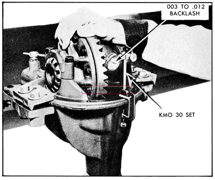
1957 Oldsmobile Measuring Back Lash
- Check tightness of the ring gear to differential case cap screws. They should be 55 to 60 ft. lbs.
- Mark the right side bearing adjusting nut, bearing cap, and carrier with two punch marks as shown in Fig. 6-19; also, mark the left side in the same manner using one punch mark. These marks will serve for location and adjusting purposes when rebuilding differential with the original gear set.
1957 Oldsmobile Marking Adjusting Nut
- Remove bearing cap, lock screws and locks.
- To determine if the side bearing pre-load is correct:
a. Loosen each bearing cap attaching bolt (1/4 to 1/2 turn) just enough to tum adjusting nut. (Tap lightly on bearing cap to assure freeness of nut in threads.)
b. Back off the right hand adjusting nut (one opposite ring gear) with Tool J-972-A and watch the outer race of the bearing.
NOTE: If the side bearing pre-load is correct, the outside bearing r ace should start to turn the instant the adjusting nut is loosened. It should continue to turn until the adjusting nut is loosened 1-1/2 to 3 notches. Count and record the notches between the punch marks on the nut and those on the carrier where bearing race stopped turning.
- Remove the bearing cap bolts, bearing cap, and adjusting nuts.
- Lift the differential case from the carrier while holding the sidle bearing outer races against rollers. (See Fig. 6-20)
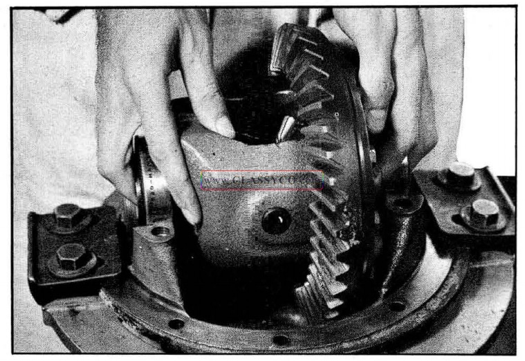
1957 Oldsmobile Removing Differential Case
DO NOT DROP OR MIX THE DIFFERENTIAL SIDE BEARING OUTER RACES. THEY MUST BE ASSEMBLED TO THEIR RESPECTIVE BEARINGS.
- Make sure the companion flange nut is tight and check pinion bearing pre-load with an inch pound torque wrench as shown in Fig. 6-21. A pre-load of less than 5 in. lbs. can cause a float noise or a ring to pinion gear back-lash “clunk”.
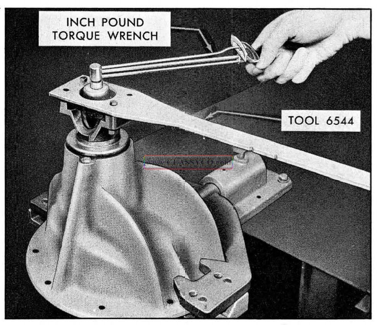
1957 Oldsmobile Measuring Preload with Torque Wrench
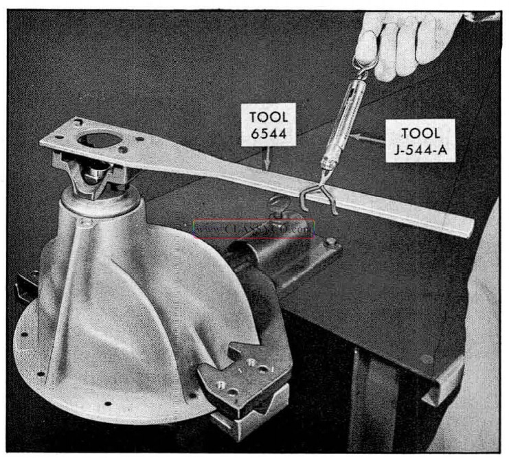
If an inch pound torque wrench is not avail able, Spring Scale J-544-A may be used by hooking to Companion Flange Holding Tool 6544 at a point 10 inches from pinion shaft center, as shown in Fig. 6-22. The reading in pounds, multiplied by 10 will give inch pounds. Thus 3 pounds on the scale will indicate 30 in. lbs. The reading BETWEEN POUND GRADUATIONS must be read in TENTHS rather than ounces. Example: 2 lbs., 8 oz., is read 2.5 lbs., which equals 25 in lbs.
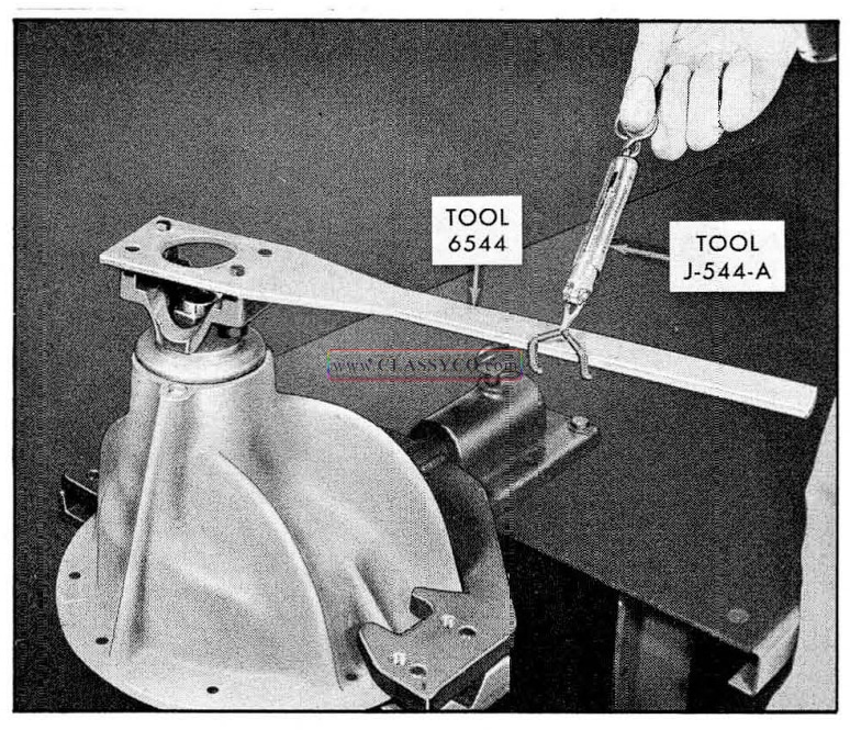
1957 Oldsmobile Measuring Bearing Preload with Spring Scale
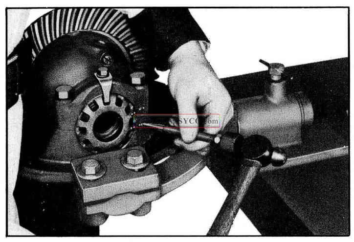
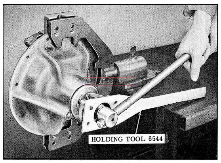
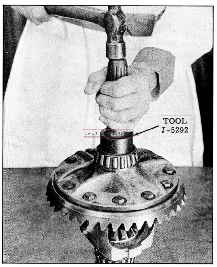
- Turn the assembly to a horizontal position as shown in Fig. 6-23; then, using Tool 6544 to hold companion flange, remove the companion flange nut using a 1-1/4″ socket.
- Remove washer.
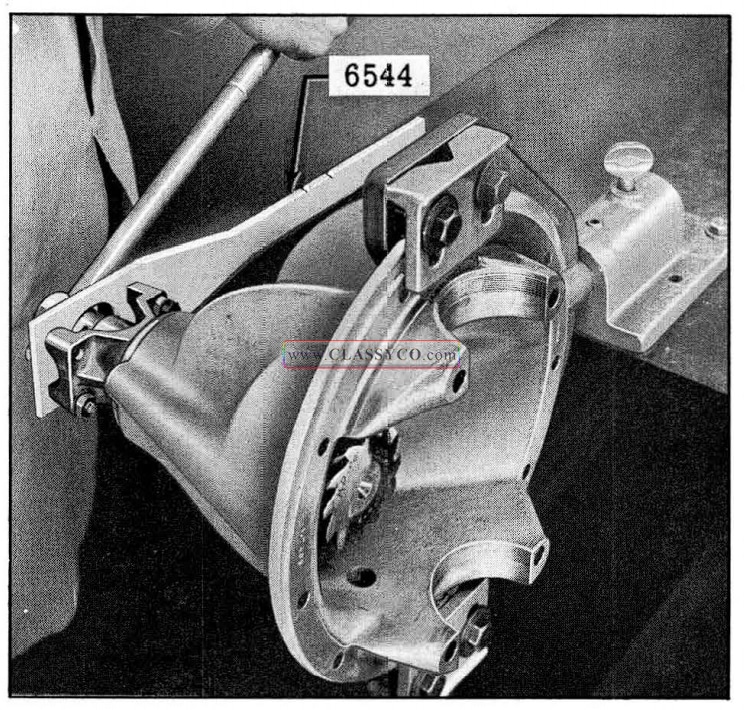
1957 Oldsmobile Removing Companion Flange Nut
CAUTION: To avoid possibility of dropping the drive pinion assembly, leave the carrier in a horizontal position until the pinion assembly is removed.
- Using companion flange puller 6295-01 and holding Tool 6544, remove companion flange. (See Fig. 6-24)
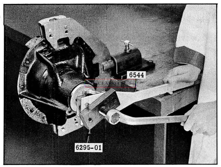
1957 Oldsmobile Removing Companion Flange (2)
- Remove the drive pinion, rear bearing, and spacer by one of the following methods:
a. Remove the ·drive pinion by hand if it has a sliding fit in front bearing.
b. If the drive pinion has a light press fit in the front bearing, lightly tap the pinion free with a composition hammer.
c. If drive pinion has a tight press fit in front bearing, remove with an arbor press. (See Fig. 6-25)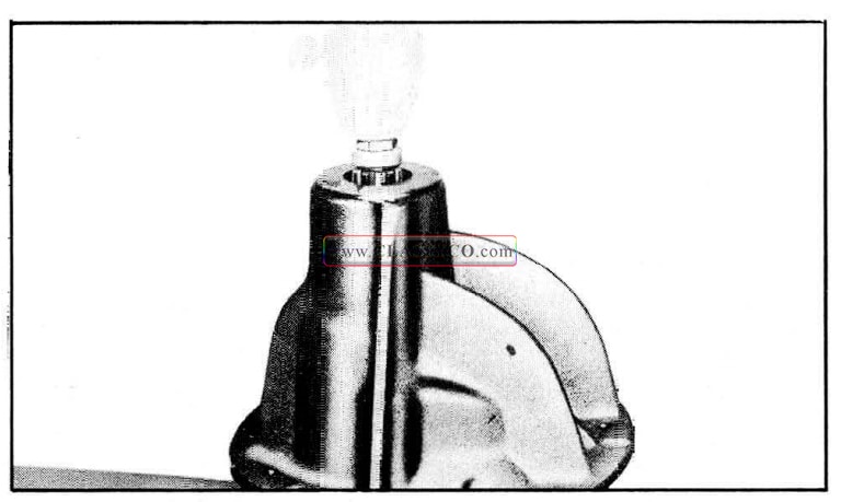
1957 Oldsmobile Removing Drive Pinion Assembly
NOTE: In all cases, a shim washer .037″ to .045″ thick will be found between the compressible spacer and inner race of the front drive pinion bearing. A second shim is used in production to salvage the compressible spacer should the recommended pre-load be exceeded. This second shim can be used by mechanics in the same manner, and its use will be covered later. No more than 2 shims are to be used.
- Remove the oil seal by driving it out of the carrier with a blunt chisel.
- Remove the front inner race and roller assembly.
- Press the front bearing outer race from carrier using Tool 6198. (See Fig. 6-26)
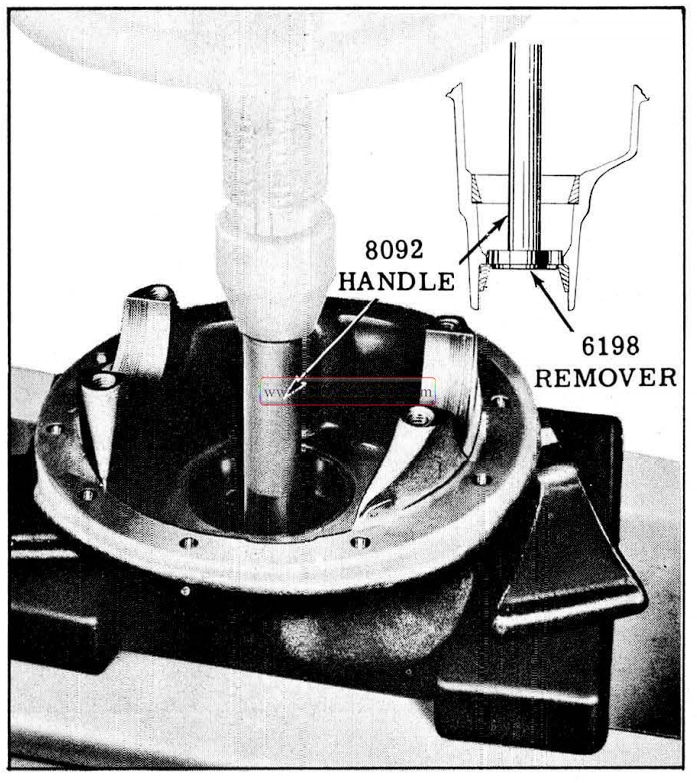
1957 Oldsmobile Removing Front Bearing Outer Race
- Press rear bearing outer race from carrier using Tool 6533. (See Fig. 6-27)
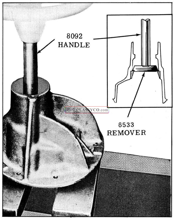
1957 Oldsmobile Removing Rear Bearing Outer Race
- If the rear pm10n bearing or shims are to be replaced, use Tool 6531 placed in an arbor press as shown in Fig. 6-28, to press the rear bearing inner race and roller assembly off the pinion shaft.
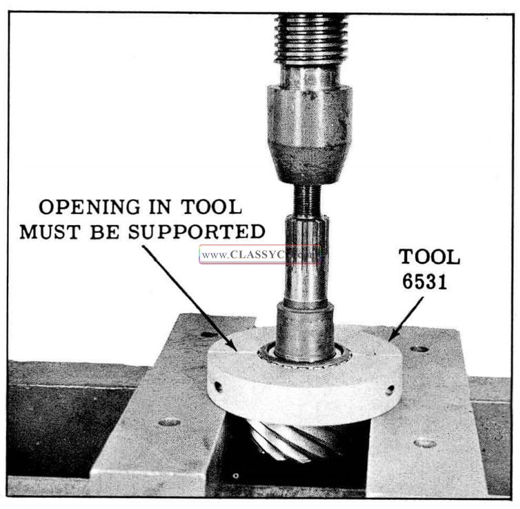
1957 Oldsmobile Removing Rear Bearing
NOTE: The shims between the pinion bearing and the pinion gear are the selective shims used to locate the drive pinion gear with the ring gear.
- Remove lock screw and pinion gear shaft, then remove the pinion gears, side gears and thrust washers from case.
- If the ring gear or differential case is to be replaced, remove ring gear from case.
NOTE: Do not remove the side bearing inner race from the differential case hubs unless the side bearings are to be replaced.
Use Differential Side Bearing Remover TR-278-R. (See Fig. 6-29) Be sure ends of puller are placed in recess in differential case. Light tapping on end of screw will aid in breaking bearing loose.
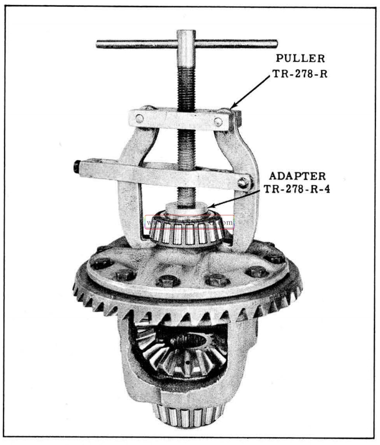
1957 Oldsmobile Removing Side Bearings
INSPECTION OF PARTS
- Clean all differential bearings thoroughly in clean gasoline (do not use a brush). Examine bearings visually and by feel. All bearings should feel smooth when oiled and rotated while applying as much hand pressure as possible.
NOTE: Minute scratches and pitts that appear on rollers and races at low mileage are due to the initial pre-load, and bearings having these marks should not be rejected.
- Examine the pinion oil seal surface of the carrier housing. Surface should be clean and free of nicks.
- Examine seal surface of companion flange for nicks, burrs, or rough tool marks which would cause damage to seal and result in an oil leak. Replace if damaged.
- Examine the differential ring gear and drive pinion teeth for nicks burrs, and scoring. Any of these conditions will require replacement of the gear set.
- Inspect the differential pinion gear shaft for unusual wear; also, the pinion and side gears and thrust washers. Black spots on copper plated pinion gear shaft may be caused by certain lubricants, but are not cause for replacement unless surfaces are deeply pitted or corroded.
- Check the press fit of the side bearing inner race on the differential case hub by prying against the shoulder at the puller recess in the case. Side bearings must be a tight press fit on the hub.
- Remove oil drain hole plug at front of carrier. Clean oil passages and carrier.
- Apply a small amount of Permatex No. 2 to outside of new plug. Drive plug flush with face of carrier.
- Diagnosis of the differential failure such as; chipped bearings, loose (lapped-in) bearings, chipped gears, etc., is a warning that some foreign material is present; therefore, the axle housing must be cleaned.
MARKING ON DIFFERENTIAL CARRIER AND PINION
Before assembling a differential, the correct number of shims to locate the drive pinion properly must be determined from markings on the differential carrier and end of pinion gear. Pinions seldom require marking.
The differential carrier is marked on the face of the flange. (See Fig. 6-30) “D” means “deep” and “S” means “shallow… depth of carrier bore to the shoulder for the rear bearing. The digit following the letter designates the number of thousandths “deep” or “shallow”.
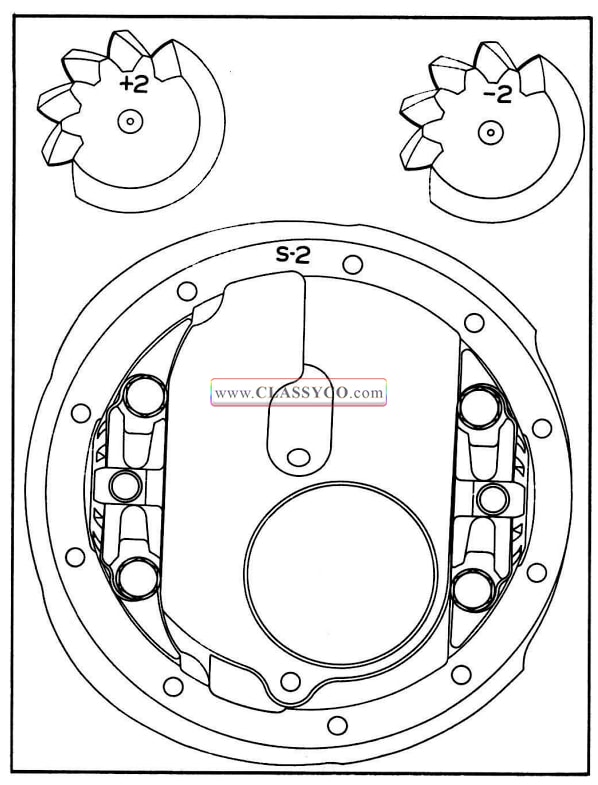
1957 Oldsmobile Pinion and Carrier Marking
If shims are required to correct an error in pinion machining, a number will be marked on the end of the drive pinion shaft indicating in thousandths of an inch the shims required to position pinion in carrier. Examples: +2 requires .002″ added shim thickness and -2 requires .002″ less shim thickness. (See Fig. 6-30)
Drive pinion shafts ground to zero specifications are not marked as they are considered “O” and do not require any more or less shims to compensate for drive pinion position.
Due to bearing thickness tolerance used in production, shim thickness as found in new differentials may very slightly from the above shim chart.
Always use the shim chart to correctly position the pinion when rebuilding a differential using new gears, bearing, or carrier.
HOW TO USE THE SHIM CHART
Read the markings on the carrier and drive pinion shaft (See Fi. 6-30) and then refer to the “SHIM CHART”. (See Fig. 6-31)
1957 Oldsmobile Pinion Shim Selection Chart
1957 Oldsmobile Pinion Shim Chart
In the column “Carrier Marking” read to the right to the “Pinion Marking” vertical column. The intersection of these columns show the correct total shim thickness for this particular carrier and pinion.
Notice on the chart, the shim requirement for a carrier marked “O” together with an unmarked pinion is.016″. This means that any “Plus” or ”Minus” markings or “Shallow” or “Deep” markings, represent the variation in shim thickness from the starting point of .016″.
Example: Carrier which is marked “D-1″ with a pinion not marked requires total shim thickness of.017”. Use shim thickness chart to identify (by color or notches) thickness of shims. Measure shims with a micrometer.
NOTE: Due to the tolerances of the bearings used in production, the shim thickness as found in differentials with original bearings may vary slightly from the service shim chart. However, always use the shim chart when installing new bearings.
If new bearings are not installed when a new pinion or carrier is installed, any variation from the chart must be taken into consideration when determining the new shim requirements.
Example: If a differential with original bearings had an unmarked pinion and a carrier marked “O”, the shim requirements according to the shim chart would be .016″. If only .013″ shim thickness was found in the differential, then obviously the bearing accounted for the.003″ variation. This variation will have to be taken into consideration when installing a new pinion or carrier.
WHEN TO USE A NEW COMPRESSIBLE SPACER
A second washer or a new compressible spacer and one washer should be used under the following conditions:
- When a new ring gear and pinion set is installed.
- When either front or rear pinion bearings are changed.
- When a new carrier is installed.
- When the compressible spacer is compressed too much and as a result the required pre-load has been exceeded during the adjustment.
If two washers are found between the spacer and bearing assembly, one washer should be discarded and a new compressible spacer used.
DIFFERENTIAL ASSEMBLY
- Press outer race of rear pinion bearing firmly in place against shoulder in the carrier. (See Fig. 6-32)
1957 Oldsmobile Installing Rear Pinion Outer Race
- Press outer race of front pinion bearing firmly against shoulder in carrier. (See Fig. 6-33)
1957 Oldsmobile Installing Front Pinion Outer Race
- Install correct number of pinion adjusting shims against. shoulder of drive pinion shaft.
- Lubricate the rear bearing roller assembly, then press the rear bearing inner race and roller assembly firmly in place against the shims on pinion shaft. (See Fig. 6-34)
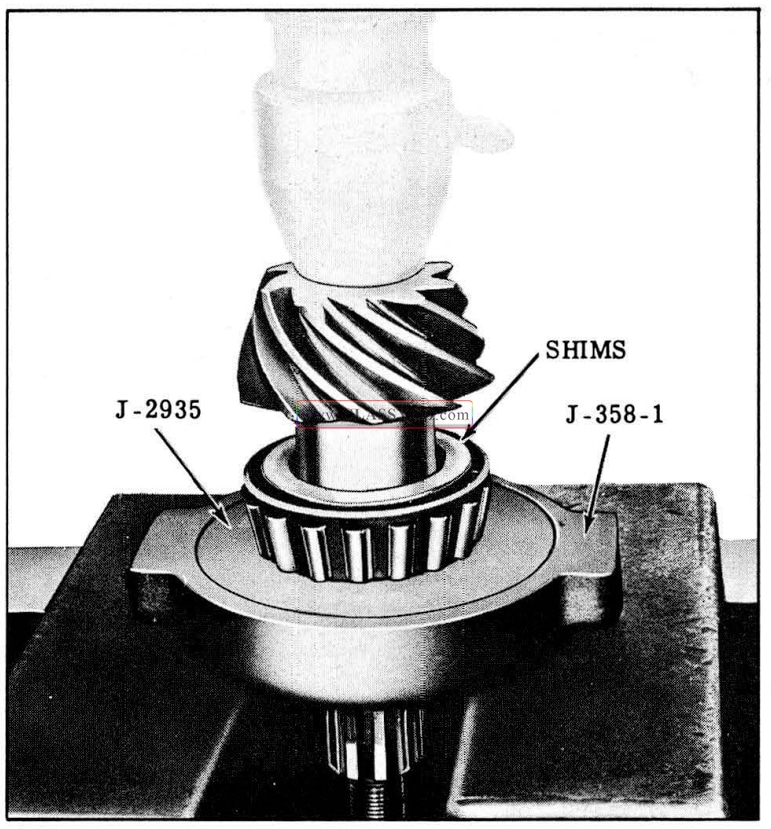
1957 Oldsmobile Installing Bearing On Pinion Shaft
- Place the compressible spacer over the drive pinion shaft (with the large diameter against drive pinion shaft shoulder). Install washer(s).
- Place the drive pinion assembly into position in the carrier. Lubricate the front bearing roller assembly and slide over the pinion shaft. Install front bearing inner race.
NOTE: If the drive pinion shaft is a press fit in the front bearing use an arbor press to install the roller and race. Use Tool J-6133 to press or drive the assembly onto the pinion shaft while supporting the pinion gear. (See Fig. 6-35)
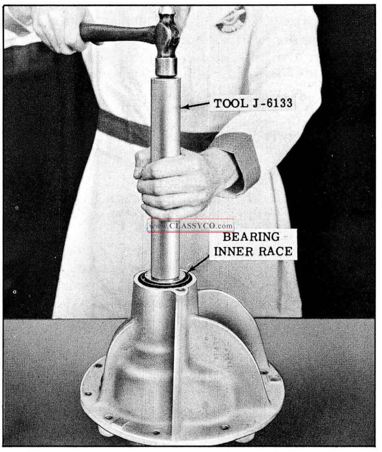
1957 Oldsmobile Installing Front Bearing Inner Race
- Coat the outer diameter of a new pinion oil seal with Permatex No. 2 (use sparingly).
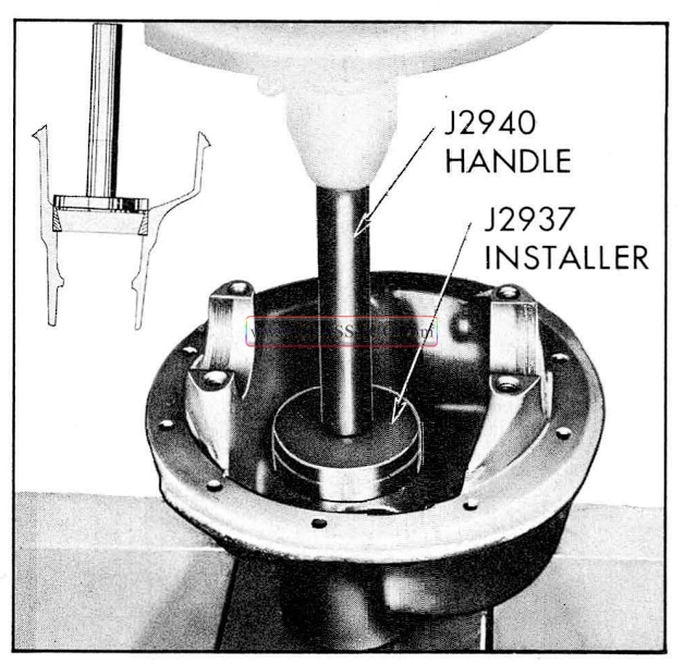
- Just start the seal into carrier by tapping lightly and then finish driving the seal in place with front pinion seal installer J-5395. (See Fig. 6-36)
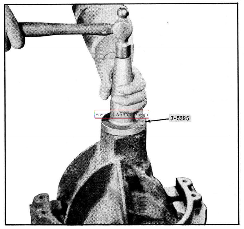
1957 Oldsmobile Installing Pinion Oil Seal (2)
NOTE: Pinion seal installer J-5395 properly locates the pinion seal to its correct depth in the carrier without possible damage to the seal retainer.
- Apply a coating of seal lubricant (Part No. 567196) to the 0.0. of the companion flange and the sealing lip of the new seal.
- While supporting the drive pinion shaft, tap the companion flange onto the pinion shaft.
- Oil the flat washer and threads of pinion shaft and then install the washer and nut but do not tighten.
Adjusting the Pinion Bearing Pre-Load
CAUTION: Extreme care must be used in tightening companion flange nut to pre-load pinion bearings correctly. Incorrect pre-load may result in bearing failure. Never back off nut to secure proper pre-load if specified pre-load has been exceeded. If specified maximum pre-load is exceeded, it will be necessary to use a new spacer or a second washer.
1957 Oldsmobile Tightening Companion Flange Nut
Position carrier assembly as shown in Fig. 6-37 and tighten companion flange nut using flange holding Tool 6544 and a heavy duty socket until all end play in drive pinion assembly is removed. Continue to tighten nut carefully, not more than 1/6 turn at a time, then turn drive pinion shaft several revolutions to seat rollers and check bearing preload with an inch-pound torque wrench (Fig. 6-38) or spring scale J-544-A. (Fig. 6-39)
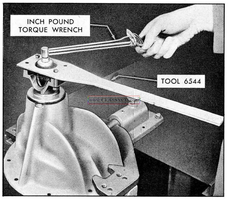
1957 Oldsmobile Measuring Bearing Preload with Torque Wrench
NOTE: If spring scale J-544-A is used to check pre-load it should be hooked to companion flange holding Tool J-6544 at a point 10 inches from drive shaft center. (See Fig. 6-39) Readings in pounds times 10 will give inch-pounds. Readings between pound graduations must be read in tenths rather than in ounces; for example, 2 lbs. 8 oz., is read 2.5 lbs. times 10 = 25 inch-pounds.
1957 Oldsmobile Measuring Preload with Spring Scale
Repeat tightening and checking until pre-load friction is 24 to 32 inch-pounds for new bearings, or 10 to 15 inch-pounds for old bearings.
ASSEMBLY OF DIFFERENTIAL CASE
- If side bearings were removed, lubricate the bearings and install as shown in Fig. 6-40.
1957 Oldsmobile Installing Side Bearings
- Lubricate the side gears, pinion gears, and thrust washers.
- Place the side gear thrust washers over gear hubs and install side gear s in case.
- While holding the upper side gear up into its bore, position one pinion gear (without a washer) between side gears and rotate gears until pinion gear is directly opposite from loading opening in case.
- Place the other pinion gear in position between side gears so that the pinion gear shaft holes are in line.
- Rotate the pinion gears in position to assure pinion gear shaft holes in gears are lined up with shaft holes in case. If not, pinion will require repositioning in side gear teeth.
- With gears properly meshed, rotate assembly just enough to permit working the pinion thrust washers into position between gears and case.
- Install the pinion gear shaft and lock it in place with lock screw and lock washer.
- Hold the differential side bearing outer races in position over the side bearings and carefully lower the differential case and ring gear assembly into carrier pedestal, engaging the ring gear with the d rive pinion gear teeth.
- Move the assembly toward the pinion until the lash between the ring gear and pinion is taken up.
- Place the adjusting nuts (right and left) in position squarely against the bearing outer races and into the threads of carrier pedestal.
NOTE: Rotate the adjusting nuts back and forth a few times by hand to be sure they are free and correctly positioned in threads. Leave the nuts snug against the bearing.
- Install the bearing caps as marked.
NOTE: The pedestal bearing caps will seat onto the carrier pedestals with proper alignment of threads if the adjusting nuts are properly seated, threads not crossed, and pedestal caps not interchanged.
- Install the cap screws (no washers are used) and draw them down only sufficient to lightly hold the caps in place. This can be done by drawing them down snugly and then loosening them approximately 1/4 to 1/2 turn.
ADJUSTING BACKLASH AND SIDE BEARING TENSION
NOTE: Whenever new parts, such as gear sets, bearings, etc., are installed, the markings on the carrier and adjusting nut (indicating the original position of gears and side bearing pre-load) should be disregarded. Whenever original parts are installed the markings can be used to reset the adjustments providing the original settings were correct.
With bearing caps tightened just snug, proceed as follows:
- Using Tool J-972-A back off the right hand adjusting nut (one opposite ring gear) approximately three turns (just enough so lash between ring gear and pinion can be removed).
- Tighten the left hand adjusting nut to move ring gear into mesh with pinion until all lash is removed, then back off adjusting nut three notches.
NOTE: This is only a starting point and may need to be readjusted depending on the back-lash present after making the following adjustments.
- Tighten the right hand adjusting nut while watching the outer race of bearing. When the bearing race starts to turn along with the adjusting nut, indicating tension on bearing, continue to tighten two notches; align closest notch in nut with cap screw hole in bearing cap.
NOTE: Tighten adjusting nut to align notch. Do not loosen.
- Tighten bearing cap bolts 70 to 75ft. lbs.
- Clamp dial indicator to differential carrier and check back-lash between ring gear and drive pinion, using dial set KM0-30. (See Fig. 6-41) If the same ring gear and pinion were installed, the back-lash should be adjusted according to markings on the bearing caps and adjusting nuts providing the differential was not disassembled to correct a noise complaint.
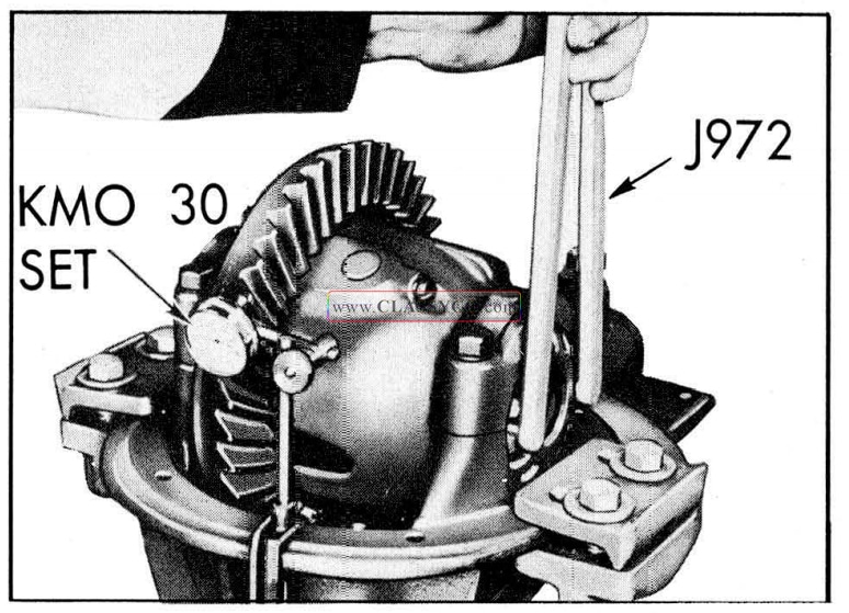
1957 Oldsmobile Adjusting Backlash
NOTE: If back-lash is not within limits, it will be necessary to adjust back-lash.007″ to .008″. To do this, and at the same time retain the two notches tension on the side bearing, proceed as follows:
- Loosen bearing cap bolts slightly, then move both adjusting nuts one notch at a time until correct back-lash is obtained.
NOTE: To increase back-lash, move ring gear away from drive pinion gear. To decrease back-lash move ring gear toward drive pinion gear.
If left nut is backed off one notch, right nut must be tightened one notch. Be sure bearing cap bolts are tightened 70 to 75 ft. lbs. each time back-lash is checked.
MEASURING PEDESTAL SPREAD
- Position gauge J-6511 over pedestal caps as shown in Fig. 6-42. Clearance should be .004″ to .012″ between gauge and machine surface of pedestal caps.
- If clearance is LESS THAN .004″, loosen the RIGHT hand side bearing cap bolts and loosen adjusting nut 1/2 notch and again tighten pedestal cap bolts and recheck clearance.
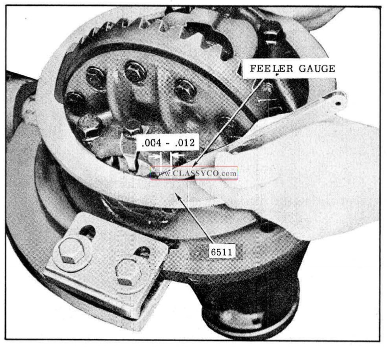
1957 Oldsmobile Measuring Pedestal Spread
NOTE: The right hand adjusting nut should be loosened more than 1/2 notch from the original two notches tight position. This will leave a side bearing tension of no less than 1-1/2 notches tight.
If when measuring pedestal spread (as outlined in step 1) the clearance is found to be MORE than .012″, then the RIGHT hand adjusting nut should be TIGHTENED 1 notch.
NOTE: The 1-1/2 to 3 notches tension on the side bearing is very important to obtain the recommend ed bearing pre-load. The.004″ to .012″ clearance between gauge J-6511 and the pedestal caps is important to obtain the recommended press fit of the carrier into the pedestal supports in the housing.
- After side bearing pre-load is correct, install bearing cap locks and lock bolts.
AXLE HOUSING ALIGNMENT
If rear tire wear indicates that the axle housing may be bent, the alignment can be checked as follows:
- Back the car squarely onto an alignment machine.
- Compensate for wheel run-out the same as for checking front wheel toe-in.
- Check the amount of toe-out, which should be 0″ to 1/ 16″.
NOTE: Due to the fact that the car is backed onto an alignment machine, the actual toe-out will be read on the scale as toe-in. However, if the toe-out is checked with a tram gauge, disregard the aforementioned.
- If a tram gauge is used for checking toe-out, it will still be necessary to perform steps 1 and 2 in order to check camber, which should be 1/4° negative to 1/2° positive.
The necessary straightening operations may be performed using frame straightening equipment without removing the axle housing from the car. This procedure will allow checks during the straightening operation to determine when the housing is within the prescribed limits.
DIAGNOSIS OF DIFFERENTIAL NOISE
When a differential assembly is suspected of being noisy, a thorough road test should be made to make sure that the noise is not being caused by tires, road surface, wheel bearings, engine, trans mission, muffler, body or propeller shaft.
TIRE NOISE – Different types of road surfaces will affect tire noise but will not affect rear axle noise. For road testing, select a level tarvia or asphalt road, as this type road surface practically eliminates tire noise. For test purposes only inflating all tires to approximately 50 lbs. pressure will materially alter noise caused by tires, but will not affect noise caused by the rear axle. Rear axle noise usually ceases when coasting with transmission in neutral at speeds under 30 m.p.h.; however, tire noise continues with lower tone as car speed is reduced. Rear axle noise always changes when comparing “pull” and “coast”, but tire noise remains about the same.
WHEEL BEARING NOISE- Wheel bearing noise may be confused with differential noise; however, a rough rear wheel bearing produces a vibration or growl which continues with car coasting with transmission in neutral. A bad bearing will cause a knock or click approximately every two revolutions of wheel since the bearing rollers do not travel at the same speed as the rear axle shaft. To determine which wheel bearing is noisy, hoist the car and spin each wheel while listening at the hub cap.
ENGINE AND TRANSMISSION NOISE – Note speed at which noise occurs, and with car standing, accelerate the engine to approximate speed where noise was noticed. If a similar noise is produced with the car standing, it cannot be due to the rear axle.
DIFFERENTIAL SIDE AND PINION GEARS – Differential side gears and pinions seldom cause noise because their movement is slight on straight ahead driving. Noise produced by these gears will be most pronounced on turns.
RING AND PINION GEAR NOISE – These generally show up as drive noise, coast noise, or float noise. Drive noise is most pronounced on constant acceleration through the speed range. Coast noise is most pronounced when the car is allowed to coast through the speed range while in gear. Float noise is the most pronounced while holding the car speed constant at various speeds. Drive, coast, and float noises will be very rough and irregular if the differential or pinion shaft bearings are rough, worn, or loose.
PINION BEARING AND CARRIER BEARING NOISE – Rough or brinelled pinion bearings pro duce a continuous whine starting at a relatively low speed. The noise is most noticeable with a light pull between 18 and 25 miles per hour.
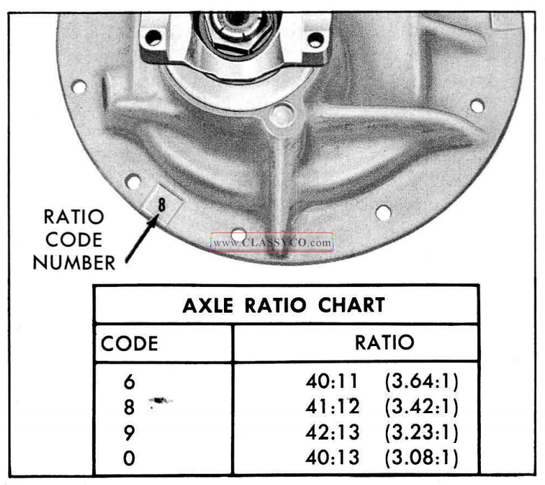
1957 Oldsmobile Rear Axle Ratio Location
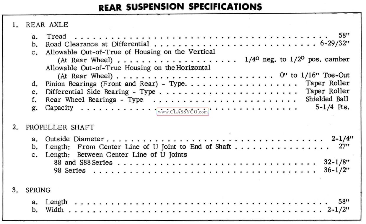
1957 Oldsmobile Rear Suspension Specifications
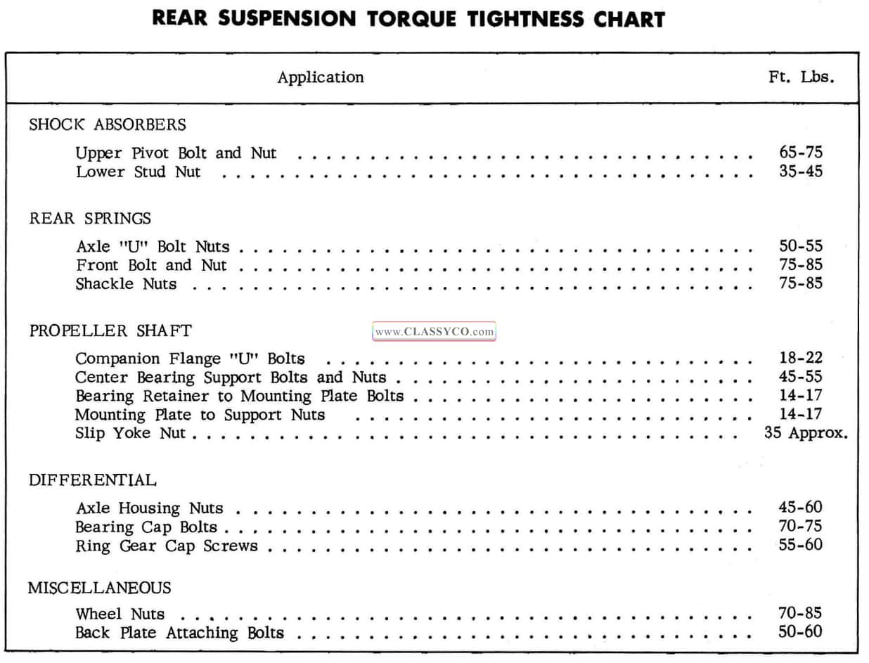
1957 Oldsmobile Rear Suspension Torque Tightness Chart
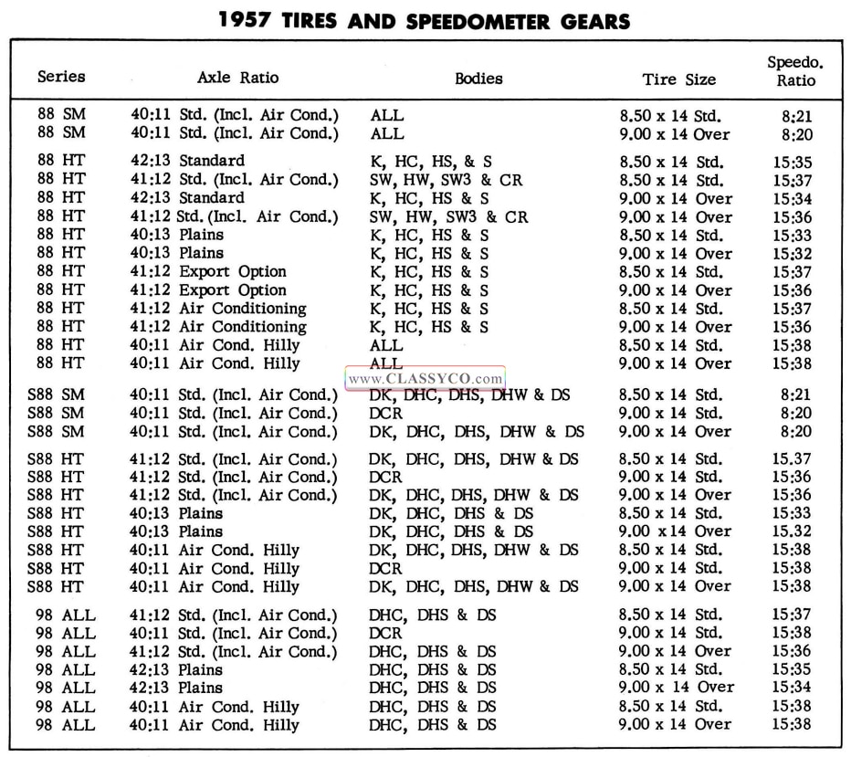
1957 Oldsmobile 1957 Tires and Speedometer Gears