INSTRUMENTS AND RADIO
NOTE: FOR TESTING AND ADJUSTING PANEL ELECTRICAL UNITS, SEE ELECTRICAL SECTION.
INSTRUMENT CLUSTER
The 1957 instrument cluster is of the printed circuit type which eliminates external wiring at each component of the cluster. All of the electrical instruments and lights are connected to the wiring harness by a plug located at the rear of the cluster.
All the instruments in the cluster are electrically operated, except the speedometer and Hydra Matic indicator, which are mechanically operated.
The generator, temperature, and oil pressure indicators use colored lights to warn the driver of conditions other than normal when the engine is operating at speeds above idle.
The light sockets used in the instrument cluster can be removed by turning the socket 1/8 of a turn clockwise. The printed circuit and all of the instruments in the cluster can be removed without removing the cluster assembly.
Instrument Cluster – Remove and Install
- Remove L.H. instrument panel molding screw and position molding away from cluster. Wind shield wiper cable and hoses do not have to be disconnected.
- Remove headlight switch, parking brake light, ignition-starter switch, and cigar lighter.
- Remove air conditioning, heater or ventilation controls if car is so equipped.
- Remove radio knobs and panel.
- Remove upper clamp from mast jacket bracket. Remove H-M indicator needle.
- Remove lower clamp from mast jacket bracket. Pull mast jacket away from bracket.
- Remove the mast jacket bracket from the instrument panel.
- Disconnect the wiring harness and speedometer cable from cluster.
- Remove the cluster to instrument panel attaching nuts and lock washers, then remove cluster from front of dash.
- To install, reverse removal procedure and align H.M. indicator needle.
Printed Circuit-Remove and Install (On Car) (Fig. 15-1)
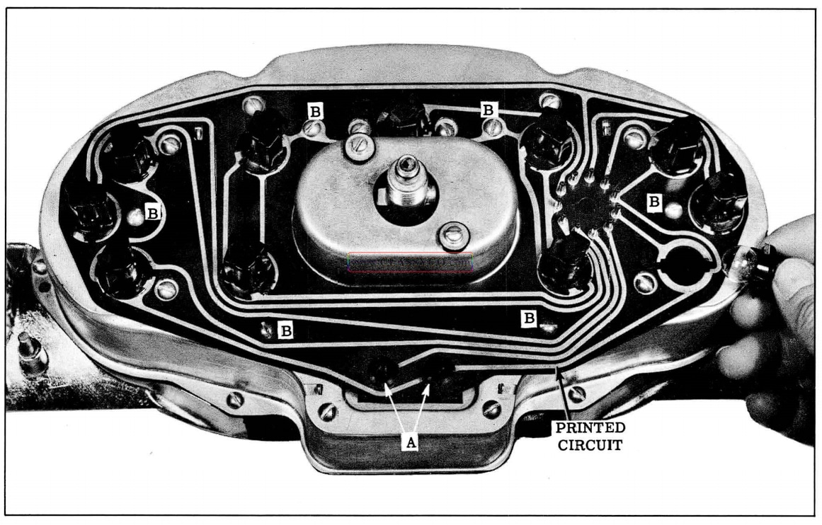
1957 Oldsmobile Instrument Cluster
NOTE: Repairs of the printed circuit are NOT recommended. Whenever the circuit develops an open or short, the entire circuit should be replaced as outlined below:
- Disconnect wiring harness and speedometer cable from cluster.
- Remove the 2 protective caps (A) from the fuel gauge, then remove the 2 nuts and washers.
- Remove light sockets.
- Remove circuit to cluster attaching screws (B) and remove circuit.
To install, reverse the above procedure.
Fuel Gauge and/or Speedometer Housing
The fuel gauge and/or speedometer housing can be removed after the printed circuit has been removed.
HYDRA-MATIC INDICATOR NEEDLE Remove and Install (Fig. 15-2)
To remove the H-M indicator needle, remove upper clamp from mast jacket bracket, loosen the Allen set screws on the shifter tube, then carefully guide the needle from the instrument cluster. To install, reverse the above procedure, using extreme care to prevent damage to the needle. Move selector lever through entire range to check for needle interference. Adjust as outlined below.
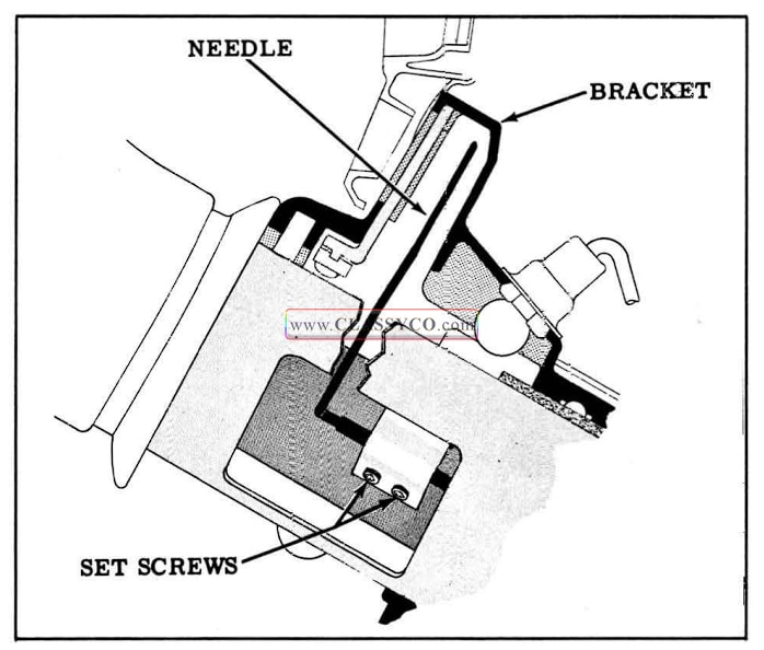
1957 Oldsmobile Hydra-Matic Indicator Needle
Adjust
With the upper clamp removed from the mast jacket bracket and the Allen set screws TIGHT ENED, move the selector lever to “Neutral ” position. Align H-M need le with “N “, then move selector lever through entire range to check needle alignment with remaining selector positions. Read just needle if necessary.
MOLDINGS
The instrument panel molding consists of two end sections and a center section.
End Moldings
To remove the end moldings, remove the attaching sheet metal screw, then slide the molding away from the instrument cluster (L.H. molding) or from the center section (R.H. molding).
NOTE: When removing the L.H. molding, it is necessary to remove the windshield wiper control.
Center Moldings
The center molding is located between the R.H. end molding and the radio panel and is attached to the instrument panel by 3 studs. To remove the center molding, it is necessary that the R.H. end molding and the radio panel be removed.
When installing center molding, be sure that anti-squeaks are properly installed.
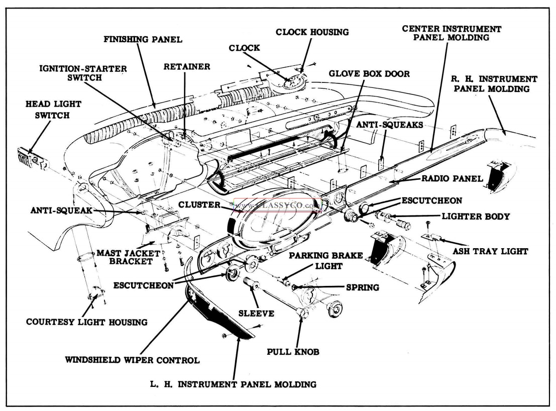
1957 Oldsmobile Instrument Panel
SAFETY PADS
(See BODY SECTION)
GLOVE BOX
(See BODY SECTION)
ASH TRAYS
Ash tray light sockets are a push-fit in their housings, which are mounted above the ash tray housing on the instrument panel.
STEERING COLUMN BRACKET
The steering column bracket is fastened to the instrument panel by two studs, washers, and nuts. Anti-squeak gaskets are used between the steering column bracket and the instrument panel.
IMPORTANT: H-M indicator needle must be removed before removing bracket. (See HYDRA MATIC INDICATOR NEEDLE)
CLOCK
The clock is electrically wound. The rewind mechanism winds the clock when the clock electrical circuit is energized (approximately every two minutes). The clock housing is retained to the finishing panel by two screws. The clock is attached to the clock housing by 2 screws. Wiring is attached at the rear of the clock and the light socket snaps into the clock housing.
COURTESY LIGHTS
The instrument panel courtesy light socket assembly is of the snap-in type, installed from behind the instrument panel. Two screws in the courtesy light rim retain the rim, lens, and housing to the panel.
PARKING BRAKE LIGHT
The parking brake light is mounted on the instrument panel. To remove, push in on the back of the unit to compress spring, and turn the socket counter-clockwise 1/8 turn.
HEADLIGHT SWITCH (Fig. 15-4)
All connections in the headlight switch are the push-in type, and are color coded.
A circuit breaker protects the parking and headlamp circuits. The tail lights are fused in the main fuse panel on the dash.
The brightness of the instrument panel lights is controlled through a variable resistor unit by turning the light switch knob right or left. A fuse on the light switch protects the resistor as well as the instrument panel light circuit.
On cars equipped with Autronic-Eye the light switch incorporates an Autronic-Eye switch, located between the pull knob and escutcheon, which permits the selection of automatic or manual headlight control.
To Remove Headlight Switch:
- Disconnect battery.
- Disconnect wiring from light switch.
- Remove knob and rod by first pulling knob out to “Headlight” position, then depress button on top of switch assembly and pull rod out.
- If car is equipped with Autronic-Eye, loosen Autronic-Eye switch knob set screw and re move switch knob.
- Remove sleeve with an Allen wrench, then remove escutcheon.
- Remove headlight switch from rear of instrument panel.
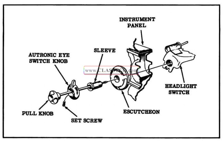
1957 Oldsmobile Headlight Switch
IGNITION-STARTER SWITCH
To Remove Switch Assembly:
- Disconnect plug on back of switch and remove light socket.
- Twist escutcheon until it can be removed from instrument panel.
- Remove the switch attaching nuts and lock washers, then remove switch assembly from underside of instrument panel.
To Remove Lock Cylinder:
- Insert key and turn to left.
- Push wire in hole in face of lock cylinder.
- Turn cylinder to left as far as it will go and withdraw cylinder.
CIGAR LIGHTER
To Remove Lighter Assembly:
- Disconnect fuse holder on back of lighter.
- Unscrew the retainer from lighter body assembly behind the instrument panel.
- Remove lighter body and escutcheon from the front of instrument panel.
NOTE: When installing cigar lighter, one of the square holes in the body assembly must point toward the light hole in the ignition switch to permit passage of light from the ignition switch lamp.
HEATER-DEFROSTER CONTROL
(See HEATING AND VENTILATING SECTION)
FRESH AIR CONTROL KNOB AND CABLE ASSEMBLY
In order to replace an air control knob, cable, or bracket, (on cars not equipped with air conditioning or heater) it will be necessary to replace the complete assembly.
To Remove assembly:
- Disconnect cable(s) from valve assembly.
- Remove nuts and lockwashers from studs at cluster and remove control assembly.
WINDSHIELD WIPER CONTROL
To Remove Control assembly:
- Disconnect cable from wiper motor.
- Disconnect vacuum hoses from control (on cars equipped with windshield washer).
- Using a small screwdriver, pry knob from control.
- Remove nut from control, then remove control from rear of instrument panel.
To install, reverse the above procedure
RADIO
The radio consists of the receiver unit and the speaker unit. The receiver units include the dial controls and p6wer supply.
The dial light is mounted in a long flexible socket which is inserted through the left side of the receiver. The serial number plate is located on the bottom of the receiver chassis and is visable through a slot in the glove box.
On cars equipped with a rear seat speaker, a variable type control located behind the manual tuning knob modulates both the front and rear speakers simultaneously. (See Fig. 15-5) As the Fader control is turned counter -clockwise, the volume of the front speaker increases while the volume of the rear speaker decreases. As the control is turned clockwise the volume of the front speaker diminishes while the volume of the rear speaker increases. After the desi red speaker modulation is obtained, the volume of both speakers can be regulated by the volume control knob.
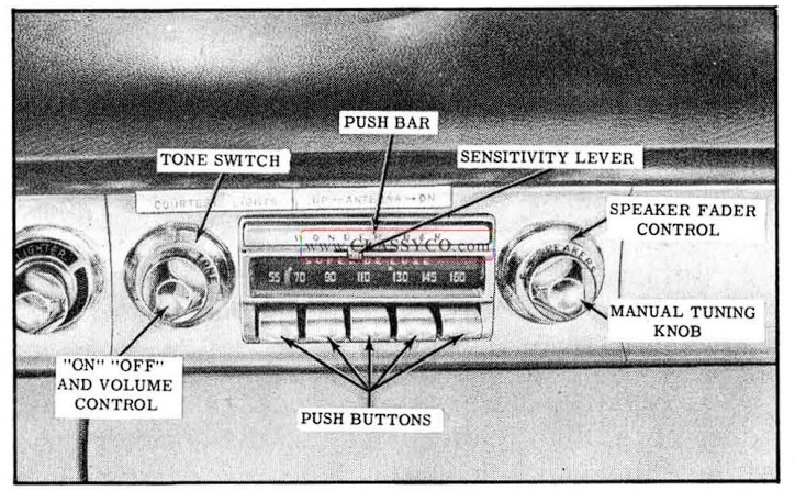
1957 Oldsmobile Super Deluxe Radio
Both the Deluxe and Super Deluxe models have 5 push buttons for touch tuning, which mechanically tunes the radio at pre-selected stations, and a control knob for manual selection of stations.
ln addition to push button tuning, the Super Deluxe model features automatic tuning. Depressing the foot selector switch or the center push bar rejects any station previously selected and automatically selects and tunes the next available station.
The sensitivity of the automatic tuning mechanism can be increased or decreased by the sliding lever located under the bar. The lever has three positions. When the lever is to the left, only the stronger or local stations will be received. The sensitivity can be increased by moving the lever to the middle or extreme right position.
PUSH BUTTON ADJUSTMENT
Adjustment of the mechanical push button tuning system on the Deluxe and Super Deluxe models are the same.
- Allow the receiver to warm up for a few minutes.
- Select a push button for the desired station. Pull the button slightly to the right and then out as far as it will go.
- Tune in the desired station manually.
- Push the selected button to its maximum IN position. This is the locking operation.
- Proceed in the same manner for the remaining stations.
- After all the buttons have been adjusted, recheck the settings. Push each button, then see if the station can be tuned in more accurately manually. If so, repeat step 2 and reset the station manually.
RECEIVER REMOVAL
To remove the Deluxe or Super Deluxe model radio receiver, proceed as follows:
- Remove radio speaker.
- Remove glove box.
- Disconnect radio lead (green) from wiring harness. (See Fig. 15-6)
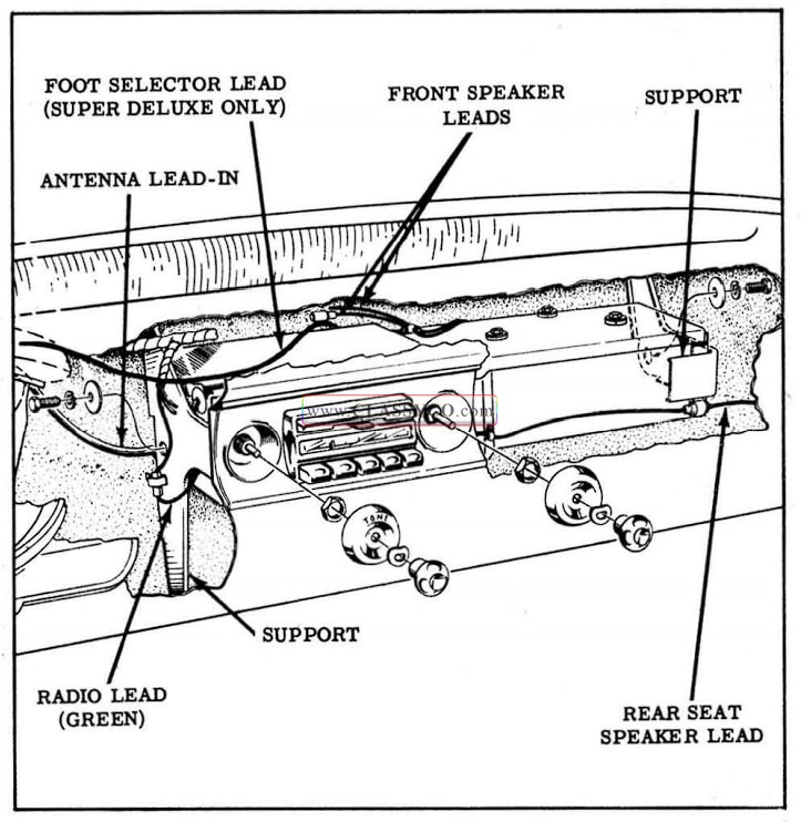
1957 Oldsmobile Receiver Removal
- On cars equipped with rear seat speaker, disconnect speaker lead.
- Disconnect antenna lead-in from receiver.
- On Super Deluxe radios, disconnect foot selector plug-in connector from rear of receiver.
- Remove knobs, nuts, and washers from radio controls.
- Disconnect receiver from receiver side supports while supporting receiver to prevent it from falling. Remove the receiver.
To replace receiver, reverse the above procedure.
FOOT SELECTOR SWITCH REMOVAL (Super Deluxe Radio)
- Fold back floor mat to expose foot switch and remove attaching screws.
- Remove foot switch wiring lead from clips along upper side of dash, then remove plug-in connector from rear of radio receiver.
To replace switch, reverse sequence of operations. Be sure to route wiring lead above cluster to provide clearance.
FRONT SPEAKER REMOVAL (Fig. 15-7)
To remove the front speaker, disconnect the speaker leads and remove the 2 speaker to baffle attaching screws.
To replace, reverse sequence of operations.
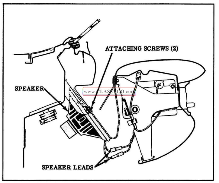
1957 Oldsmobile Front Speaker Mounting
REAR SEAT SPEAKER (Fig. 15-8)
The rear seat speaker is mounted under the parcel shelf, and is accessible through the trunk compartment. To remove speaker:
- Disconnect lead from terminal.
- Remove 4 mounting nuts, lockwashers, and flatwashers, while supporting speaker to prevent it from dropping.
To replace, reverse sequence of operations, being careful to avoid damaging the speaker cone while aligning the mounting holes over the mounting screws.
NOTE: On “98” models the speaker mounting studs are welded to the parcel sheIf and no speaker bezel or screen is required.
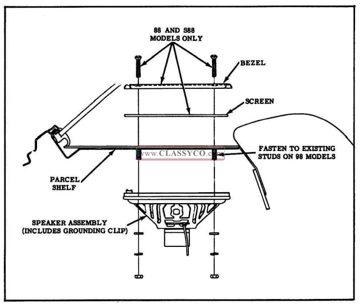
1957 Oldsmobile Rear Seat Speaker
ANTENNA
TRIMMER ADJUSTMENT
- With the antenna fully extended, turn the radio on.
- Turn the volume control full on and tune the receiver to a weak station between 600 and 1000K.C. on the dial.
- With a small screwdriver adjust the antenna trimmer on bottom of receiver for maximum volume.
CHECKING ANTENNA
To check antenna for partial short, remove lead-in from side of receiver and check resistance from lead-in connector to a good ground using an ohmmeter. Resistance should be 3 megohms or more.
MANUAL ANTENNA REMOVE AND REPLACE
To remove the antenna mast, loosen the antenna cap nut and lift the mast out of socket. To remove antenna socket and lead-in, proceed as follows:
- Remove left cowl trim panel.
- Remove lead-in plug from left side of radio receiver.
- Remove antenna mast; then remove cap, nut, upper spacer, and rubber gasket. (See Fig. 15-9)
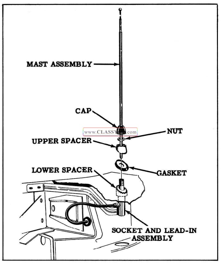
1957 Oldsmobile Manual Antenna
- Remove screws holding antenna lead-in brace to inside ledge of fender.
- Remove lead-in assembly from under fender, being careful not to lose lower spacer, and pull lead-in cable out through rubber grommet in cowl.
To replace antenna, reverse sequence of operations. Be sure metal is clean where antenna brace attaches to inside ledge of fender. Position antenna so that it tilts back slightly. Tighten brace screws, then tighten thin nut. The cap should be turned down finger-tight to prevent water entering the antenna socket and resulting in poor reception.
POWER ANTENNA
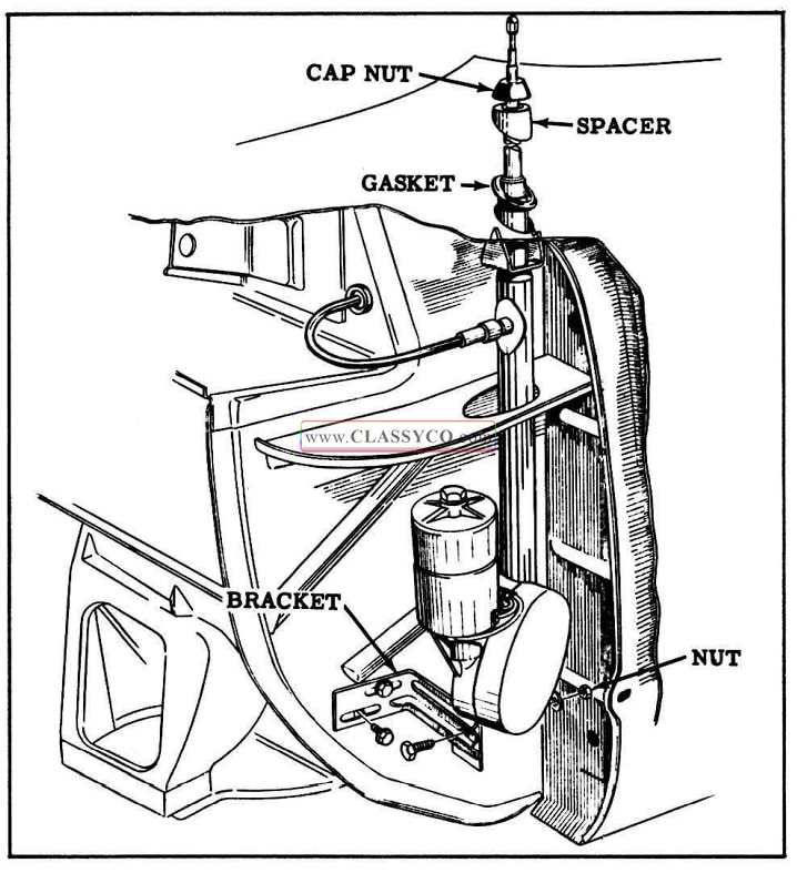
1957 Oldsmobile Power Antenna
REMOVAL
- Lower antenna. If antenna will not retract, clean, straighten, and lubricate mast sections, then assist lowering operation with hand pressure. If the motor is inoperative check for blown fuse and check control switch for proper contact by shorting across switch terminals.
If antenna will not lower after the above measures have been taken, it will be necessary to cut off mast above cap nut.
- Disconnect battery.
- Remove left cowl trim panel. Disconnect ground lead from cowl. Disconnect motor wires from antenna switch.
- Remove antenna lead wire (white) from fuse block, then push lead wire and harness through grommet in cowl.
- Disconnect antenna lead-in at antenna tube.
- Remove nut and washer from bracket.
- Raise front of car to allow clearance for antenna removal.
- Remove cap nut using Tool J-5185-1.
- Remove spacer and gasket.
- Remove the antenna assembly by lowering from under fender.
INSTALLATION
- Install antenna assembly from under fender. Guide upper end of mast through fender and install gasket and spacer. Install cap nut finger tight. Connect antenna lead-in cable to body tube.
- Install antenna to cowl mounting bracket.
- Connect motor to switch wires. Fasten ground wire to cowl.
- Connect antenna lead wire (white) to fuse block.
- Connect positive battery cable and check antenna for proper operation.
- Replace cowl trim panel.
- Align antenna by adjusting mounting bracket to motor attaching screws. Tighten cap nut with Tool J-5185-1 one full turn beyond finger tight position.
ELECTRIC ANTENNA DIAGNOSIS
If antenna fails to operate, check for the following possible sources of trouble.
- See that fuse in block is not burned out.
- Examine electrical connections at switch: made sure they are securely connected.
- Check wiring at switch with lamp or meter.
- Stalling or slowly operating motor may be caused by bent antenna sections.
- Excessive tightening of cap nut on fender will result in excessive operating noise in the car.
1957 Oldsmobile 88 Holiday Sedan (HS)