FRAMES
The frames for all1957 models are entirely new to provide for Pivot Poise Suspension and the two piece propeller shaft.
When supporting car on a jack or floor stands, the car should be supported at the suspension points only. Under no condition should the car be supported at the center of ”X” member or at extreme ends of frame.
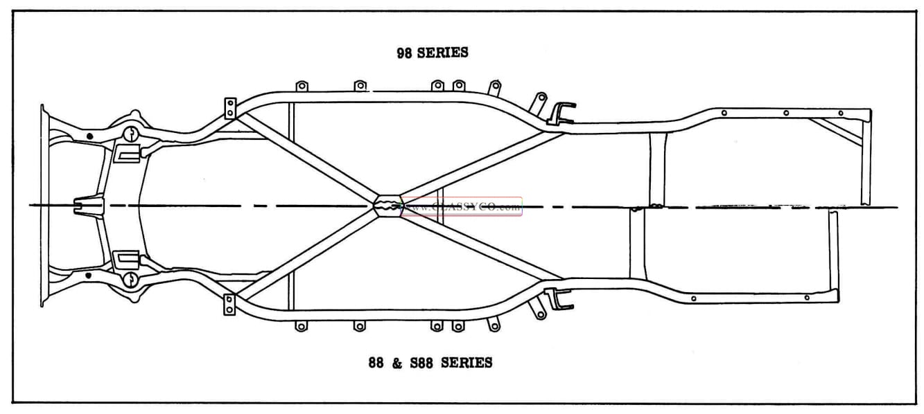
1957 Oldsmobile Frames
CHECKING FRAME ALIGNMENT
The diagram shown in Fig. 12-2 can be used to check the alignment of a car frame that has been distorted.
The reference points indicated in the figure are transferred to a level floor by means of a plumb bob. The dimensions between the various reference points shown in the figure compared with similar points on the frame to be checked, will show where straightening operations are necessary.
To check for frame misalignment at any point in the frame, proceed as follows:
- Place car on clean, level floor and set brakes.
- Drop plumb bob and mark floor from corresponding points, as indicated, on each side of the frame.
- Move car and make all measurements between the marks placed on the floor.
NOTE: Corresponding measurements must equal within 1/4″.
- Measure A-A. If not equal, rear end of frame is misaligned. If A-A are equal, mark point on floor where lines cross.
- Measure B-B. If not equal, center portion of frame is misaligned. If B-B are equal, mark point on floor where lines cross.
- If A-A are equal and B-B are equal, draw center line through the points where A-A and B-B cross.
If the center line passes over the pilot· hole mark, then frame alignment is correct. If the center line does not pass through the pilot hole mark, then the forward part of frame is misaligned.
In the event that collision had occurred from the rear end of the automobile, center line could be produced by starting from the pilot hole mark on the floor ana producing line through the point where B-B crosses.
If collision had occurred in the middle portion of the frame, then center line could be produced by means of the pilot hole mark and the intersection of A-A.
THE FOLLOWING CHECK CANNOT BE MADE UNTIL IT IS DEFINITELY DETER MINED THAT THE FRAME IS PROPERLY ALIGNED.
- C-C not equal, then front suspension cross member has shifted.
- If C-C are equal, then position of front sus pension cross member MAY be correct. Measure D-D; if not equal, front suspension cross member has shifted.
- O-O not equal, then lower control arm is’ bent.
- N-N not equal, then the rear axle housing is bent or has shifted.
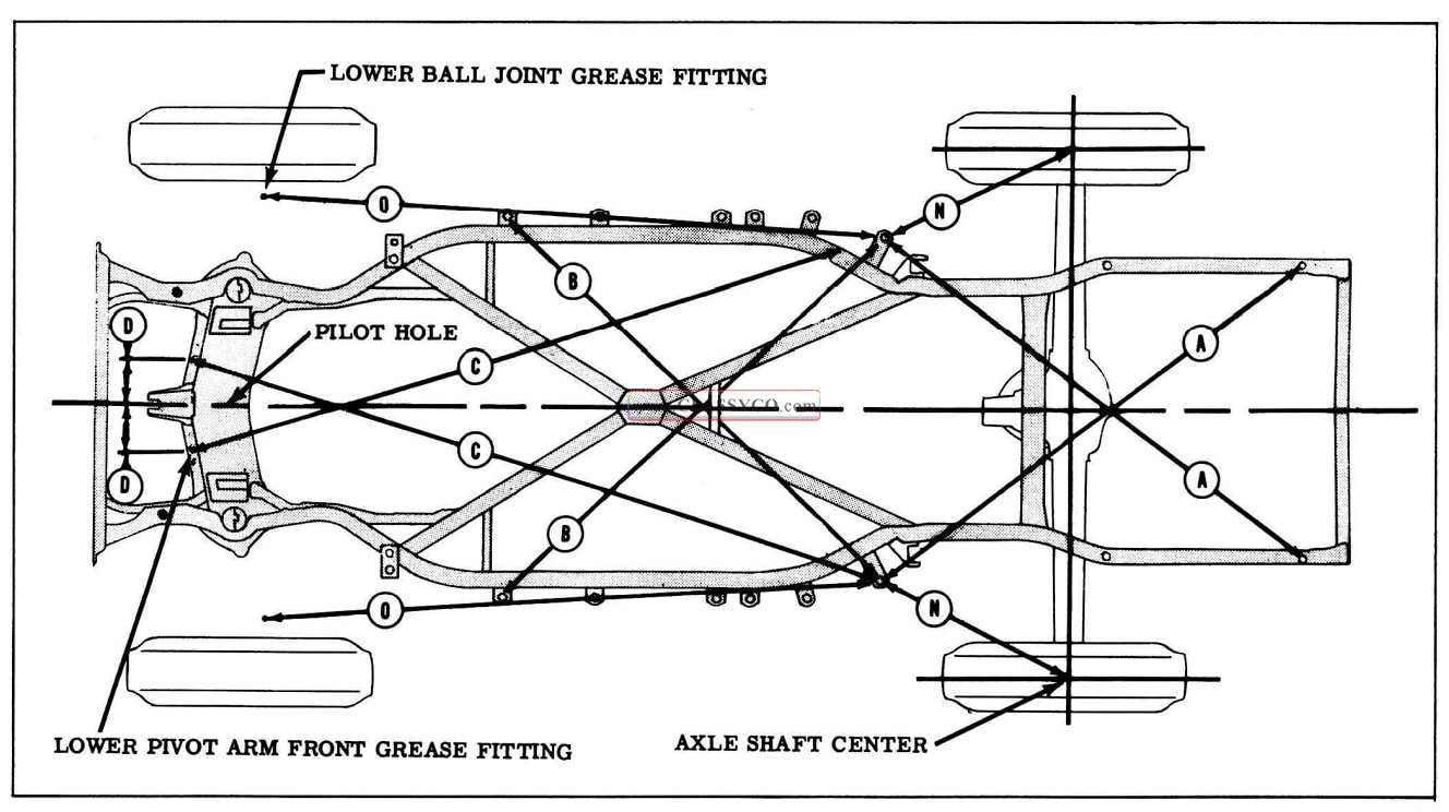
1957 Oldsmobile Frame Alignment Diagram
STRAIGHTENING FRAME
In case of collision, frame members can often be satisfactorily straightened to the required limits. Since the front suspension cross member is made to unusually close limits necessary for proper front wheel alignment, straightening of this unit may not be successful.
It is possible that the ordinary straightening methods will suffice for minor damage; however, in case of serious damage or fracture, the entire front suspension crossmember must be replaced. Before the member is replaced, it is essential that the frame alignment be checked, and corrected if necessary.
Whenever possible, the parts should be securely fastened with hot rivets. In case riveting equipment is not available, finished bolts snugly fitted in reamed holes may be used. The nuts should be securely tightened and lock washers used, care being taken that washers do not spread. (Cold driven rivets are not recommended unless the heavy power press equipment necessary to make secure fastening is available.)
When the frame repair is completed and inspected, the various parts of the front suspension may be assembled.

1957 Oldsmobile Bumper Torque Specifications
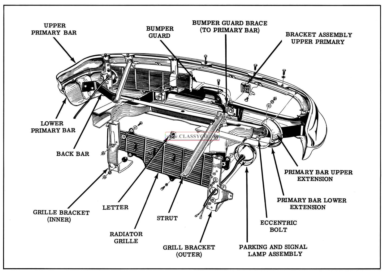
1957 Oldsmobile Front Bumper Assembly
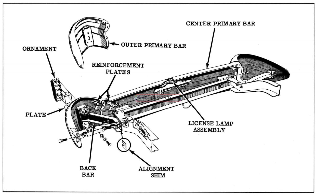
1957 Oldsmobile Rear Bumper Assembly
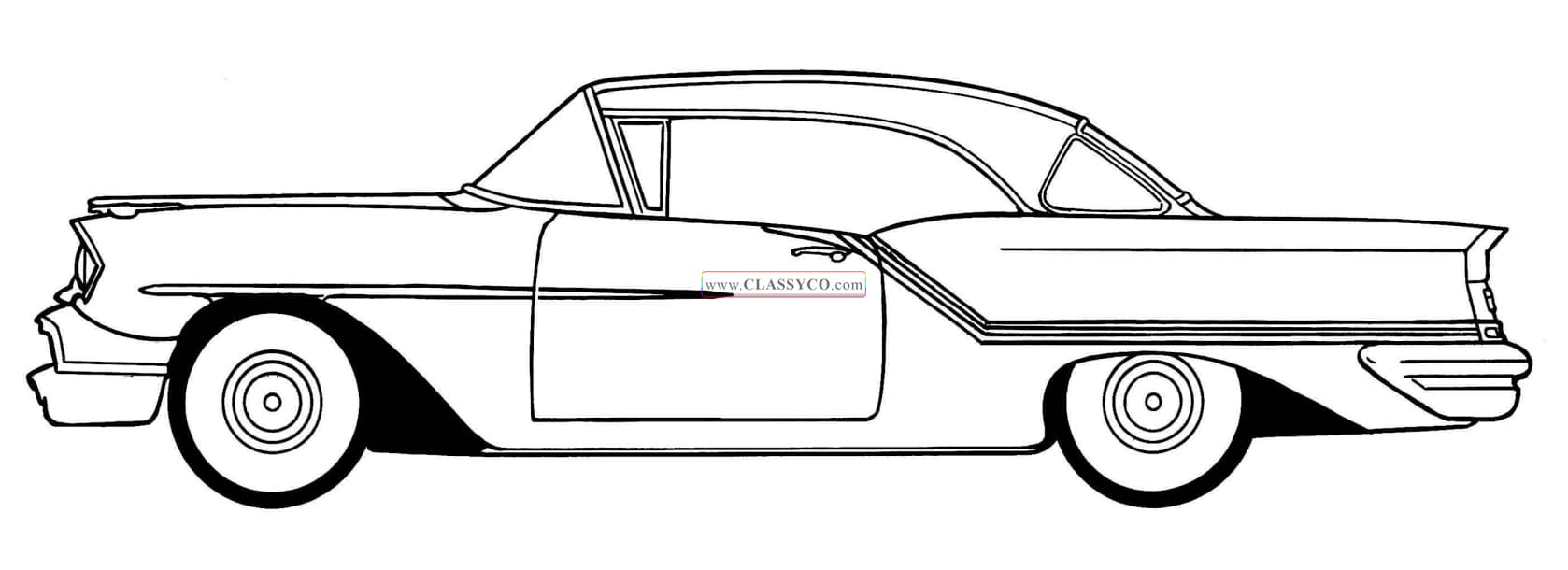
1957 Oldsmobile 88 Holiday Coupe (HC)