CARBURETION
ROCHESTER CARBURETOR MODEL 4GC
GENERAL DESCRIPTION
The 1957 4GC carburetor is the same design as used in 1956 except for two new features:
A. A redesigned choke system incorporating a choke modifier. The primary purpose for the choke modifier is to prevent “loading up” or excessively rich mixtures during the warm-up period.
B. A flapper valve is used under the idle vent valve in the air horn. This valve is of composition material and is not removable for service. The purpose of this valve is to prevent spilling of fuel out of the idle vent valve.
THEORY OF OPERATION
The following description will consider and assume the carburetor as basically two dual carburetors incorporated as one complete unit. These theoretical two carburetors will be referred to as the Primary Side and the Secondary Side. The Primary Side completely controls the metering of fuel to the engine throughout the idle and part throttle range. The fuel delivered from the Primary Side is supplemented by fuel from the Secondary Side during the power or wide open throttle range.
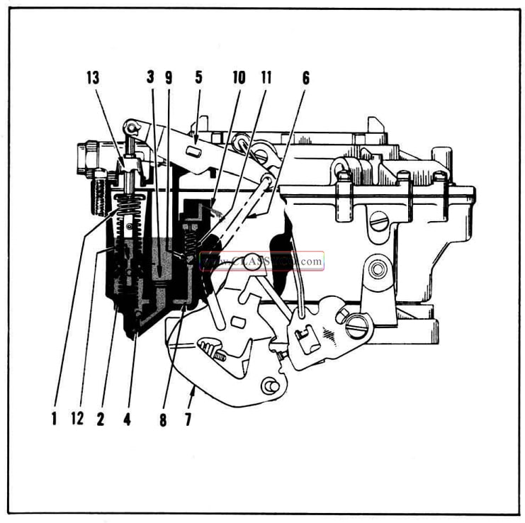
Float System (Fig. 8-76)
To aid in maintaining the correct fuel level in bot!) float bowls under all conditions of operation, the Rochester 4GC carburetor employs two sets of twin floats.
All fuel enters the carburetor on the primary side. Some of this fuel then passes through a channel cored in the air horn and enters the inlet passage on the secondary side at (9). As the fuel on the primary side drops, the twin floats (2), also drop, thus moving the inlet needle (3) off its seat (4). Then pressure from the engine fuel pump forces fuel through the filter screen (5) into the inlet passage (6), thru the small filter screen (7), and then into the float bowl. As the fuel level in the bow1 rises, the floats rise and once again close off the inlet needle.
As fuel is drawn from the float bowl on the secondary side of the carburetor, the float action is identical with that on the primary side. As the twin floats (8) drop, pressure from the fuel pump forces fuel through the fuel inlet (1) and filter screen (5). It then passes through the small filter screen (10) and needle seat (11) and into the float bowl. As on the primary side, when the fuel level rises, the floats rise and close off the inlet needle.
Both float systems are provided with float needle pull-clips (12 and 13). The inlet needles are pulled from their seats by a drop in fuel level in the float bowls. This is to prevent the possibility of gum deposits causing a sticking condition.
Both sides of the carburetor are individually and internally vented by the channels shown at (14 and 15). These vents transmit the air pressure from beneath the air cleaner to the fuel in the float bowl. The amount of fuel metered by the carburetor is dependent upon the pressure in the float bowl causing fuel to flow. By locating the vents below the air cleaner, or internally, the carburetor automatically compensates for air cleaner restriction, since the same pressure causing air to flow will also be causing fuel to flow.
A cored passage in the float bowl, slightly above the normal fuel level, links the primary and secondary float bowls together. In this way, any abnormal rise in level on one side will be absorbed by the other and should not seriously disrupt the operation of the engine.
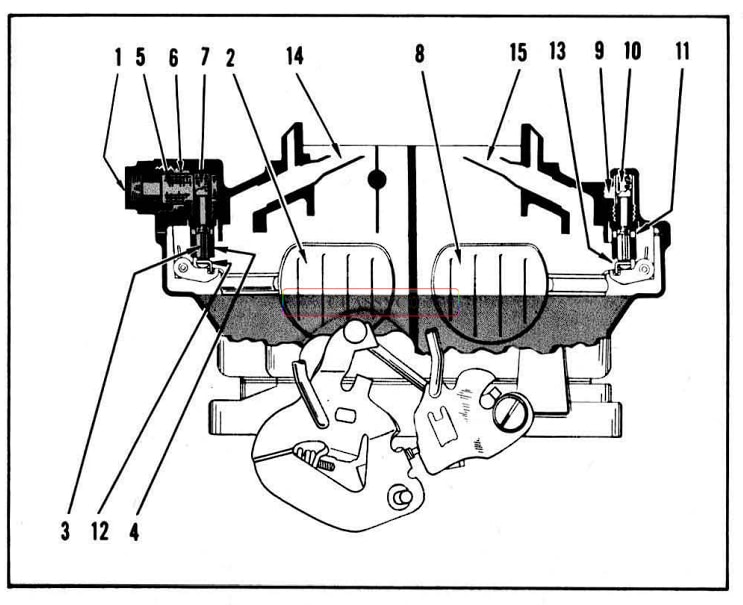
1957 Oldsmobile Float System
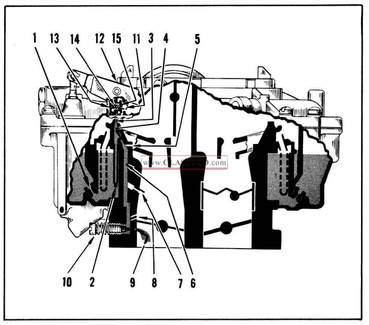
Idle System (Fig. 7-77)
At small throttle openings, the vacuum created by the main venturi is not sufficient to cause fuel to flow from the nozzles. Therefore, an additional system has been provided to furnish the proper mixture ratios required throughout the low speed range.
An adjustable idle system is provided on the primary side of the carburetor which supplies the fuel required for normal curb idle as well as that required for operation in the off idle, low speed range. The idle fuel is drawn from the float bowl through the main metering jets (1) into the fuel well in the bottom of the float bowl. Air joins this fuel at the calibrated primary idle air bleeds (3) and at the secondary idle air bleeds (5) and passes down through a vertical idle channel (6). At the lower end of the channel additional air joins the mixture through the lower idle air bleeds (7) and secondary idle discharge holes (8). The resultant mixture is then discharged into the throttle bore from the idle needle holes (9).
As the throttle valves are opened from the curb idle position, the air entering the secondary idle discharge holes (8) gradually diminishes. When these holes become exposed to manifold vacuum they then become fuel discharge holes to meet the increased demand of the engine.
Further opening of the throttle valves increases the air velocity through the carburetor sufficiently to cause the air to strike the end of the extended lower idle air bleed (7), thus creating a lower pressure within the bleed tube. As a result, fuel begins to discharge from this bleed tube and continues to do so throughout the part throttle and wide open throttle ranges, supplementing the nozzle delivery.
To adjust the idle mixture, a tapered needle (10) is used to vary the amount of manifold vacuum applied to the idle system. When the needle is screwed in, it lowers the vacuum applied to the system and the idle mixture becomes leaner.
In order to minimize difficult hot weather starting or rough idling due to fuel vapor formation, the model 4GC carburetor incorporates an external vent which functions when the throttle valves are in the closed position. This external idle vent consists of an actuating lever (11) attached to the pump shaft and lever assembly (12), idle vent valve guide (13), idle vent valve spring (14) and idle vent valve (15).
When the throttle valves are closed, the actuating lever contacts the spring loaded vent valve and holds it open, permitting vapors from the float bowl to vent themselves to the atmosphere. As the throttle valves are opened, the idle vent spring closes the vent valve, thus eliminating the atmospheric vent and returning the carburetor to an internal balance.
1957 Oldsmobile Idle System
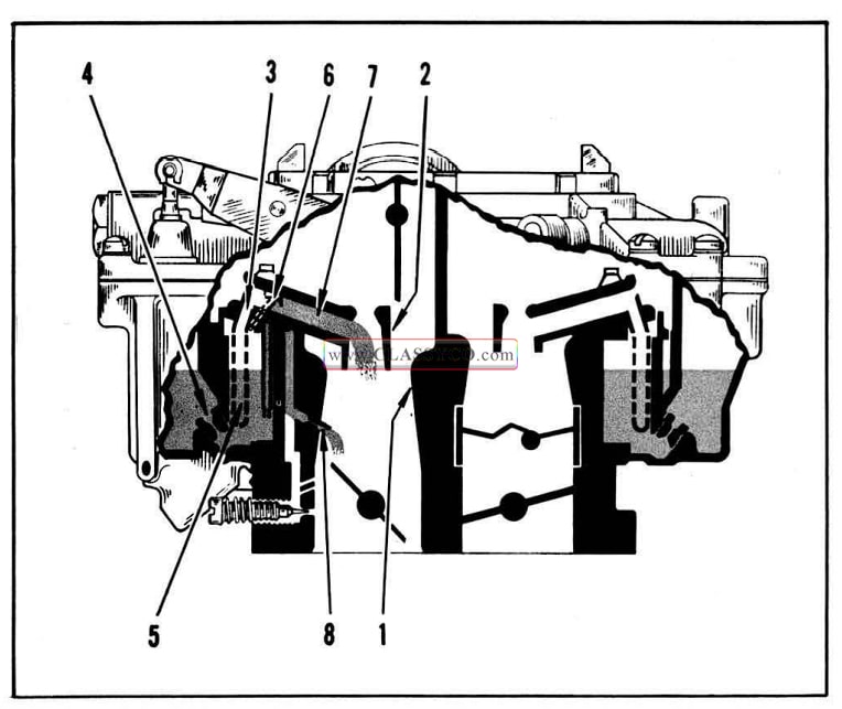
Part Throttle System (Fig. 8-78)
As the throttle valves are opened to a greater degree and more air is drawn through the carburetor, it is necessary to provide means, other than the idle system, for supplying additional fuel to meet the engine requirements. The primary side of the carburetor meets the increased demand for fuel in the following manner:
At a point of sufficient throttle opening, manifold vacuum, multiplied several times in the primary (1) and secondary venturi (2), is transmitted to the tip of the main well tubes or main discharge nozzles (3). This. vacuum draws fuel from the float bowl through the calibrated main metering jets (4) and into the main well tubes (5). After passing through the main well tubes (5) air joins the mixture at the main well bleeds (6). The mixture then passes from the tip of the nozzle through the mixture passage (7), to the secondary venturi (2), and on into the intake manifold.
As the throttle opening is progressively in creased and more fuel is drawn through the main well tubes, the fuel level in the main well drops. The calibrated holes in the main well tubes are proportionately exposed to the air in the upper well area. When this occurs, they become air bleeds, mixing progressively more air with the fuel passing through the main well tubes. Thus, although the nozzle suction is increased by in creasing the throttle opening, the fuel mixture to the engine remains constant throughout the part throttle range.
As mentioned in the idle system, as throttle opening increases, the lower idle air bleeds (8) become part throttle feed nozzles in the main bore below the primary venturi (1). The secondary throttle valves of the carburetor do not open until the primary linkage engages the secondary throttle shaft. They will then open fully during the final few degrees of primary throttle travel. The secondary side, therefore, only supplies fuel in the power range. The part throttle or intermediate range is controlled completely by the primary side of the carburetor.
1957 Oldsmobile Part Throttle System
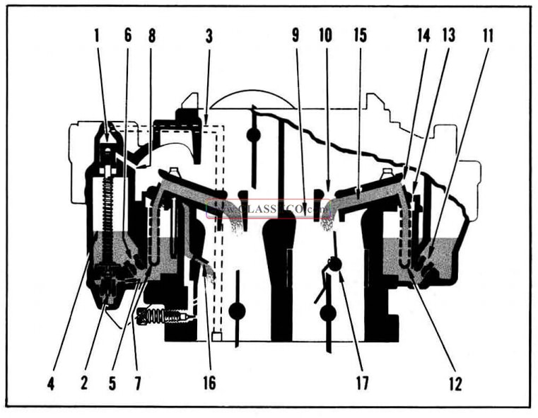
Power System (Fig. 8-79)
To achieve the proper mixtures required when more power is desirable or sustained high speed driving is to be maintained, the model 4GC carburetor employs the use of a vacuum-operated power piston (1) in the air horn and a power valve (2) in the float bowl.
This power system is located on the primary side of the carburetor. The power piston vacuum channel (3) is exposed to manifold vacuum beneath the throttle valves. The vacuum in this channel varies directly with manifold vacuum. In the idling and part throttle ranges, the manifold vacuum is normally quite high. This vacuum is sufficient to hold the power piston (1) in its extreme up position. However, as the throttle valves are progressively opened, the vacuum drops.
When the vacuum drops below approximately 9″ hg. the calibrated spring (4) beneath the power piston forces the piston down. This situation occurs at very high driving speeds or on rapid accelerations. When the piston drops down, it unseats the spring loaded power valve (2). This permits additional fuel to flow from the float bowl through the calibrated power restrictions (5) and into the main wells.
The additional fuel supplements that already flowing through the main metering jets (6) and main well tubes (7), (on the primary side) thus making the mixture being delivered to the manifold considerably richer than normal part throttle mixtures.
This power mixture continues to be supplied as long as the manifold vacuum remains below approximately 9″ hg. When the manifold vacuum again increases sufficiently, the force of the power piston spring (4) is overcome and the piston is drawn up, thus returning the carburetor to the economical part throttle mixtures. It will be noted that the power piston cavity in the carburetor air horn is connected to the main air flow passage by a vacuum break hole (8). It is the purpose of this hole to prevent the transfer of vacuum acting on the piston from acting also on the top of the fuel in the float bowl. Any leakage of air past the upper grooves of the piston will be compensated for by this vacuum break hole and will not affect carburetor calibration.
It is also in this range that the secondary side of the carburetor provides additional air and fuel to the engine for increased power. For high speed operation, beyond the part throttle range, the throttle linkage engages the secondary throttle valves and opens them completely in the remaining few degrees of primary throttle travel. In this range manifold vacuum acting on the secondary side of the carburetor is multiplied at the primary (9) and secondary (10) venturi and draws fuel from the float bowl through the calibrated main metering jets (11) into the main wells. This fuel then passes through the main well tubes (12) and is bled in a manner similar to that described previously in the operation of the primary main well air bleeds.
This mixture is bled further at the main well bleeds (13) and is then drawn to the tips of the main well tubes (14). It then passes through the mixture passage (15) to the secondary venturi (10) and is discharged into the intake manifold.
The lower idle air bleed (16) also supplies fuel throughout the power range in a manner similar to that described under the part throttle system operation.
The auxiliary valves (17) provide a means for controlling secondary bore opening according to air velocity at wide open throttle. High velocity allows good metering and also holds the valves open, so that the secondary metering system can supply fuel-air mixture.
Low velocity, in turn, reduces metering efficiency. When this condition occurs, the spring tension overcomes the velocity and closes the valves. Air, which was going through four bores, now passes through only two; the velocity is, therefore, twice as high and good metering control is thus extended over a wider range of low speed, wide-open-throttle operation.
1957 Oldsmobile Power System
Pump System (Fig. 8-80)
When the throttle is opened rapidly the air flow and manifold vacuum change almost instantaneously, while the heavier fuel tends to lag behind, causing a momentary leanness. The accelerating pump provides the fuel necessary for smooth operation during rapid acceleration. It will be noted that since the throttle valves on the secondary side of the carburetor, remain fully closed throughout part throttle operation, it is only necessary to have one accelerator pump which is located on the primary side of the carburetor.
A double spring pump plunger is used on the model 4GC carburetor. The rates of compression of the top spring (1) and the bottom spring (2) are calibrated to insure a smooth sustained charge of fuel for acceleration. On the pump intake or upstroke of the plunger, fuel from the float bowl passes through the pump filter screen (3). It unseats the aluminum inlet ball (4), and fills the pump well. The accelerator pump is connected through the inside pump lever (5), pump shaft and lever assembly, and pump rod (6) to the throttle lever (7).
Upon acceleration or down stroke of the pump plunger, the force of fuel in the pump well seats the inlet ball (4). The fuel is then forced through the discharge channel (8), to unseat the pump outlet ball (9), and then discharges through the pump jets (10) into the air stream. At the end of the discharge, the outlet ball is returned to its seat by the spring (11), which prevents air being drawn back into the fuel channel during the intake stroke.
The pump plunger head has been vented to minimize the effect of fuel percolation in the pump well. This has been accomplished by the design of a ball check and seat in the plunger head (12). In this manner any build-up of fuel vapors in the pump well will rise and by-pass the ball, thus venting themselves into the float bowl. There is, therefore, always a charge of solid fuel beneath the plunger head for rapid acceleration. Without this feature, any vapor pressure build-up would evacuate the charge of fuel in the pump system, causing poor initial acceleration as well as difficult hot weather starting.
The carburetor also makes use of a pump plunger shaft dust boot (13) which serves the dual purpose of preventing dirt and foreign material from entering the fuel bowl through the shaft opening on the top of the air horn and also provides the proper seal necessary to maintain the correct air horn vent pressure within the fuel bowl.
1957 Oldsmobile Pump System
Choke System (Fig. 8-81)
The model 4GC carburetor employs the use of a fully automatic choke to insure proper starting and driving during cold weather operation. Choking of the carburetor is necessary only on the primary side because the secondary throttle valves are locked in the closed position whenever the choke valve is even partially closed. This is accomplished by a secondary throttle shaft lockout lever and a slot in the fast idle cam. Whenever the choke valve is closed, the lockout lever prevents opening of the secondary throttle valves. However, when the choke valve is wide open, the fast idle cam drops down so that the lockout lever clears the cam, thus permitting the secondary throttle valves to open.
The choke system is composed of a thermostatic coil (1), vacuum piston (2), offset choke valve (3), and fast idle cam. Its operation is controlled by a combination of intake manifold vacuum, the off set choke valve, atmospheric temperature, and exhaust manifold heat.
When the engine is cold, the thermostatic coil is calibrated to hold the choke valve (3) closed. As the engine is started, air velocity against the offset choke valve causes it to open slightly against the torque of the thermostatic coil (1). In addition, intake manifold vacuum is applied to the vacuum piston (2) through the vacuum channel (4) which also tends to open the choke valve. There fore, the choke valve assumes a position where the torque of the thermostatic coil is balanced against vacuum pull upon the choke piston and air velocity against the offset choke valve, thereby causing a regulated air flow into the carburetor which provides a richer mixture during the warm up period.
During the warm-up the vacuum piston (2) serves to modify the choke action to compensate for varying engine loads or acceleration. Any acceleration or increased load decreases the vacuum exerted on the choke piston. This allows the thermostatic coil to momentarily increase choke valve closure to provide the engine with a richer mixture for acceleration.
As the engine warms up, hot air from the exhaust manifold is drawn into the thermostatic coil housing (5). This hot air causes a rise in temperature which in turn causes the coil to slowly relax its tension. Thus the choke valve is allowed to move gradually to the full open position.
To prevent stalling during the warm-up period, it is necessary to run the engine at a slightly higher idle speed than for a warm engine. This is accomplished by the fast idle screw which rests on the steps of the fast idle cam. The fast idle cam is linked to the choke valve shaft by the choke rod, choke trip lever and choke lever and collar assembly. This holds the throttle valves open sufficiently during the warm-up period to increase the idle RPM until the choke valve moves to the full open position.
While the automatic choke is in operation, the driver may wish to advance the throttle to the full wide open position. Since this would decrease pull upon the vacuum piston (2), thereby closing the choke valve, it is necessary to provide increased carburetor air flow by opening the choke valve mechanically. To accomplish this, a tang on the fast idle cam is made to contact the throttle lever at wide open throttle position so as to sufficiently open the choke valve. This is also called a choke unloader and serves to dechoke a flooded carburetor during starting operation whenever the engine is cranked with the accelerator held fully depressed.
1957 Oldsmobile Choke System
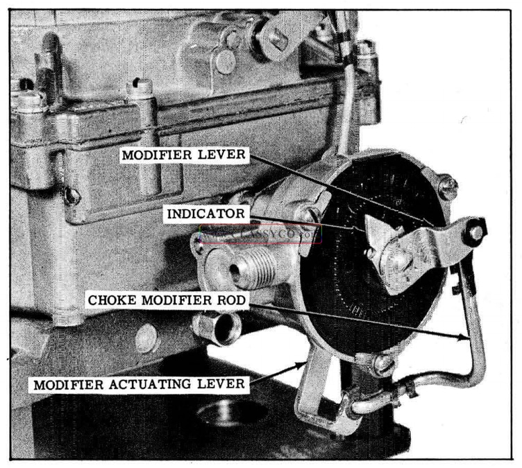
Choke Modifier (Fig. 8-82)
The choke system as used on the model 4GC carburetor, also incorporates a choke modifier. The purpose of the choke modifier is to prevent “loading up” or excessively rich mixtures during the warm-up period.
Under normal operating conditions, the automatic choke valve assumes a position where the torque of the thermostatic coil is balanced against the vacuum pull of the choke piston plus air velocity against the offset choke valve. As the heat from the exhaust manifold relaxes the tension on the thermostatic coil, the choke valve gradually opens.
When the engine is started cold and the throttle is opened considerably, vacuum pull on the choke piston is lessened, thereby causing the choke valve to close because the balance between the tension on the thermostatic coil and vacuum pull on the choke piston is upset. Also, vacuum drawing heat to the thermostatic coil housing may not be sufficient to heat and relax the thermostatic coil before “loading up” takes place. The choke modifier, being linked directly to the throttle by means of the throttle shaft modifier lever (1), choke modifier rod (2), thermostat modifier lever (3), and indicator (4), is actuated by the slightest throttle movement. Thus, the thermostat modifier lever rotates the thermostatic coil, thereby relaxing the tension on the coil and allowing the choke valve to open sufficiently to prevent “loading up”.
The choke modifier is at its leanest point at approximately 45° throttle opening. As the throttle valves are opened to fully wide open position, the choke modifier enriches the mixture.
1957 Oldsmobile Choke Modifier
CARBURETOR DISASSEMBLY
Disassembly of Air Horn
- Mount the carburetor on Holding Fixture J-59238.
- Remove the fuel inlet fitting and gasket, then remove the filter screen from the air horn.
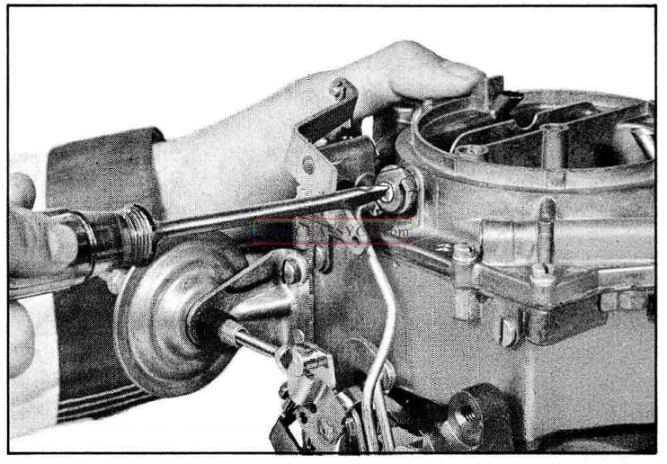
- Disconnect the intermediate choke rod at the upper end by removing the spring clip, then remove the intermediate choke rod. (See Fig. 8-83)
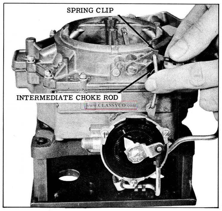
1957 Oldsmobile Removing Intermediate Choke Rod
- Unhook the spring clip from the upper end of the pump rod at the pump lever.
- Remove the horseshoe type retainer from the lower end of the pump rod, then remove the rod.
- Remove the small retainer screw holding the choke trip lever to the choke shaft, then remove the trip lever. (See Fig. 8-84)
1957 Oldsmobile Removing Trip Lever
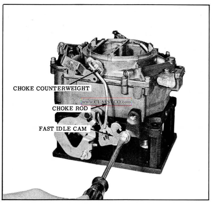
- Remove the fast idle cam attaching screw, then remove the fast idle cam, choke rod, and choke counterweight as an assembly. (See Fig.8-85)
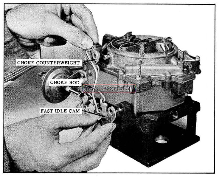
1957 Oldsmobile Removing Fast Idle Assembly
- Remove the two small brass choke valve retaining screws and discard. Slide the choke valve from the shaft and remove the choke shaft. (See Fig. 8-86)
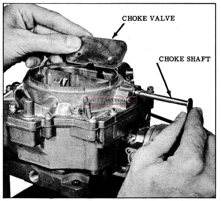
1957 Oldsmobile Removing Choke Valve
- Remove the 13 air horn attaching screws, in eluding the one screw recessed in the top of the air horn. (See Fig. 8-87)
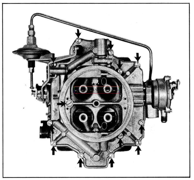
1957 Oldsmobile Air Horn Attaching Screws
- Carefully lift the air horn straight up until the float assemblies are clear of the carburetor body. (See Fig. 8-88)
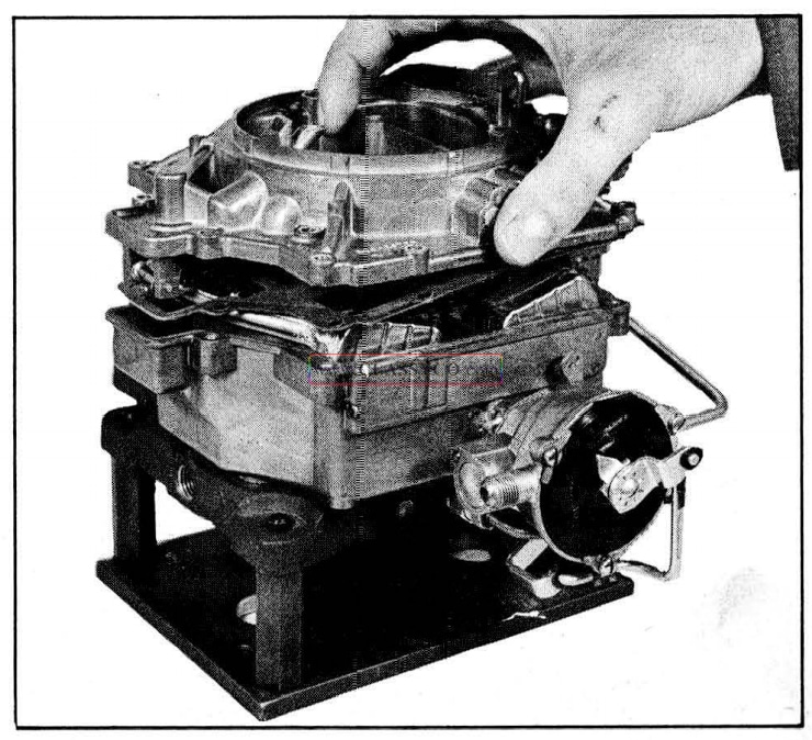
1957 Oldsmobile Removing Air Horn
- Remove the hinge pin from the primary float assembly, then lift the float and needle from the air horn. (See Fig. 8-89)
1957 Oldsmobile Float Assembly
- Remove primary float needle seat and gasket, using Tool BT-52.
NOTE: The float needle and seats are factory matched and must be installed in pairs. Never mix needles and seats.
- Remove the hinge pin, float assembly, needle seat and gasket from the secondary side of the air horn.
NOTE: It is unnecessary to remove the small fuel filter screens in the needle seat bores unless they are to be cleaned or re placed.
- Remove the power piston assembly by de pressing the stem and allowing it to snap back into position. (See Fig. 8-90)
1957 Oldsmobile Removing Power Piston
- Remove the horseshoe type retainer from the pump plunger shaft.
- Remove the pump plunger assembly by sliding the shaft through the rubber sea. Remove the rubber seal from the top side of the air horn casting.
Disassembly of Carburetor Body
- Disconnect the two spring clips at the ends of the choke modifier rod, then remove the rod. (See Fig. 8-91)
1957 Oldsmobile Removing Choke Modifier Rod
- Remove the three choke cover attaching screws and retainers, then remove the choke cover and gasket.
- Carefully lift the baffle plate from the choke housing. (See Fig. 8-92)
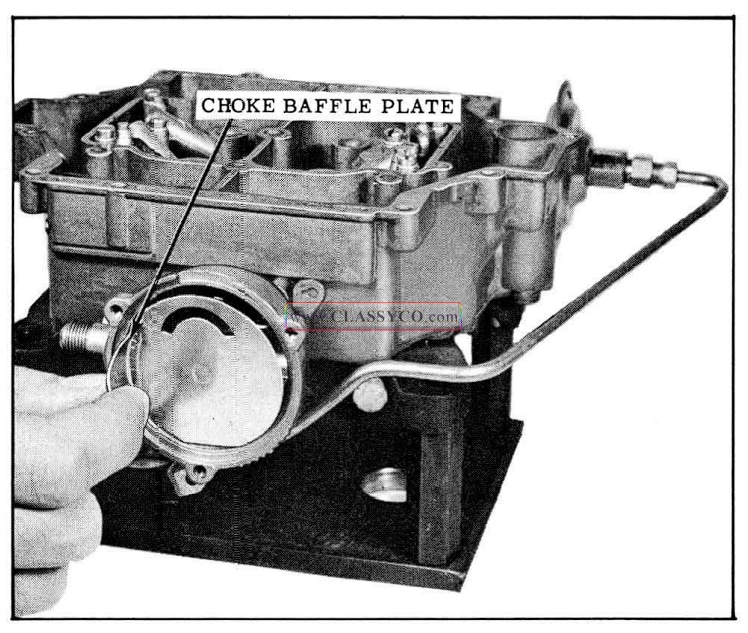
1957 Oldsmobile Removing Baffle Plate
- Remove the choke piston lever attaching screw, then remove the lever, link and piston assembly from the choke housing. (See Fig. 8-93)
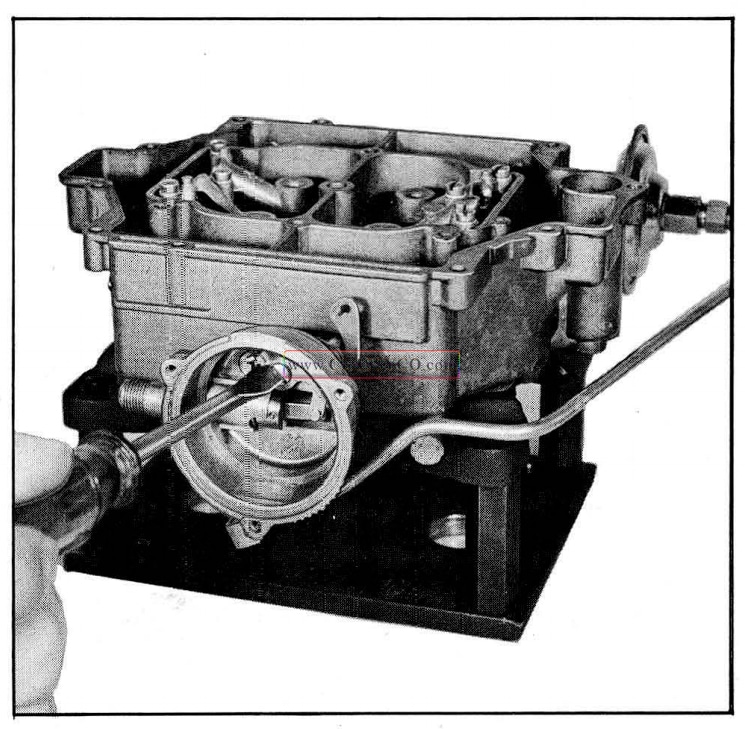
1957 Oldsmobile Removing Choke Piston Assembly
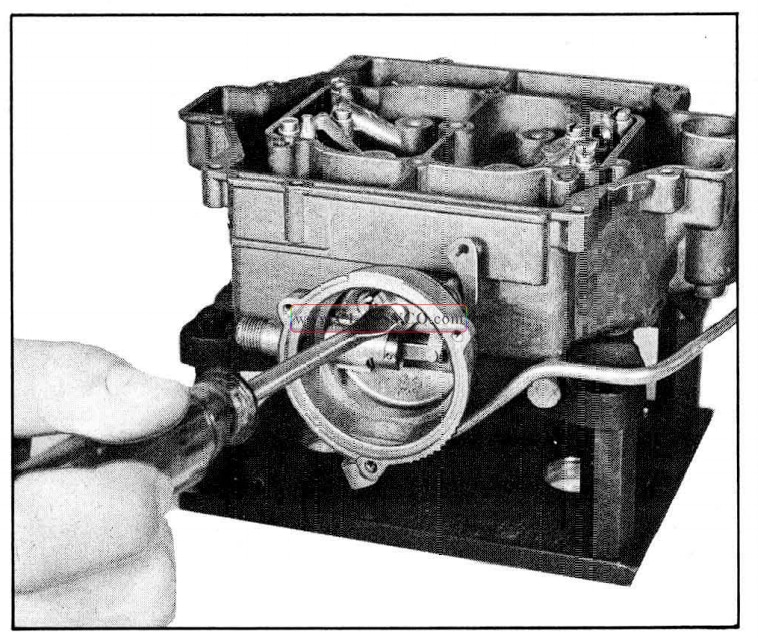
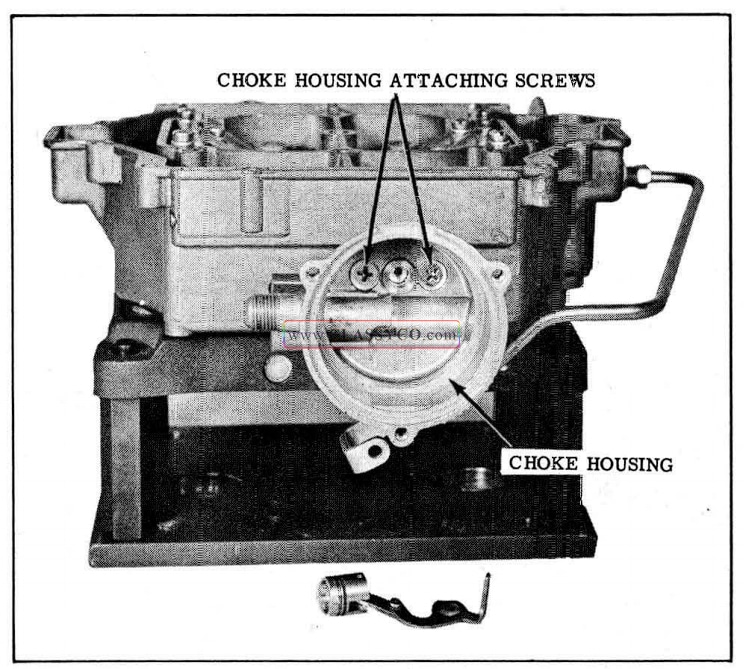
- Remove the two choke housing attaching screws, then remove the choke housing from the carburetor body. (See Fig. 8-94)
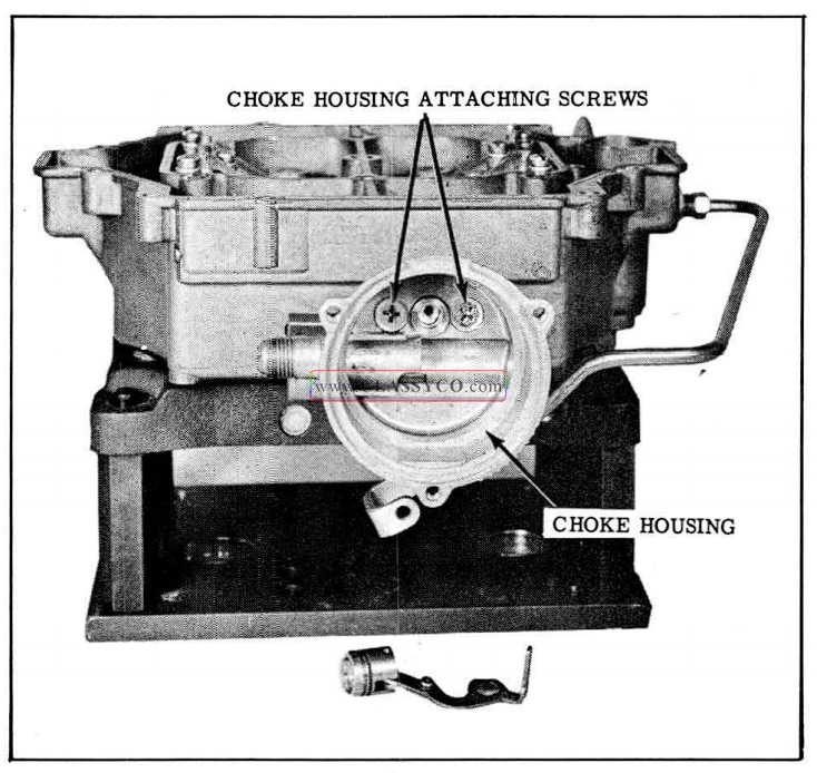
1957 Oldsmobile Removing Choke Housing
- Remove the intermediate choke shaft and rod from the choke housing.
- Disconnect the throttle return check vacuum line at the throttle flange.
- Remove the throttle return check attaching screw, then remove the return check from the carburetor body. (See Fig. 8-95)
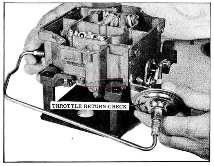
1957 Oldsmobile Removing Throttle Return Check
- Remove the three attaching screws and lock washers from the venturi cluster on the primary side, then carefully remove the cluster and gasket. (See Fig. 8-96)
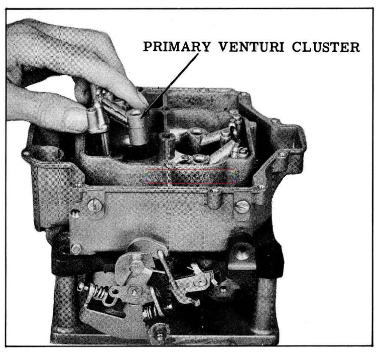
1957 Oldsmobile Primary Venturi Cluster
- Remove the three attaching screws and lock washers from the venturi cluster on the secondary side, then carefully remove the cluster and gasket.
- Remove both metering jets from the primary (pump) side of the carburetor body. (See Fig. 8-97)
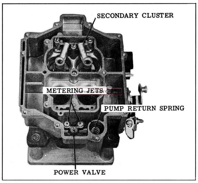
1957 Oldsmobile Primary Metering Jets
- Remove the power valve and gasket.
- Remove both metering jets from the secondary side of the carburetor. Keep them in a separate group.
- Remove the pump return spring from the pump well, then invert the carburetor body to re move the aluminum pump inlet ball from the well.
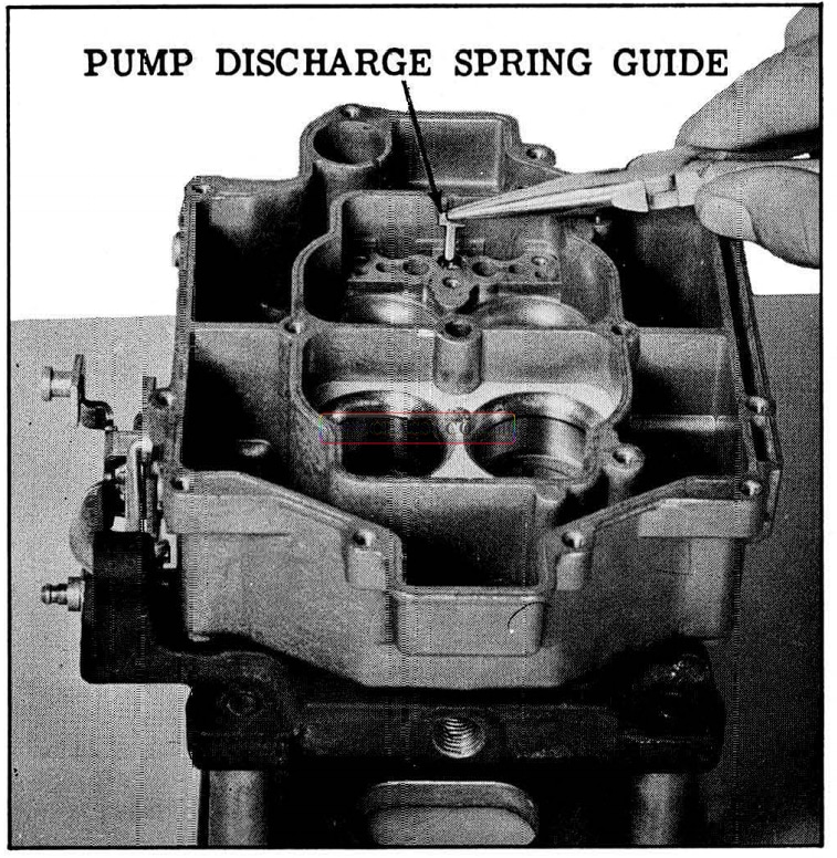
- Remove the small “T” shaped pump discharge spring guide, then remove the small spring and steel ball. (See Fig. 8-98)
1957 Oldsmobile Pump Discharge Valve
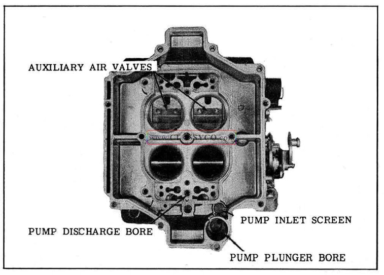
- If it is necessary to clean or replace the small screen in the bottom of the fuel inlet cylinder, remove the retainer ring and screen. (See Fig. 8 -99)
1957 Oldsmobile Pump Inlet Screen
- Invert the carburetor body and re move the four throttle flange attaching screws. Remove the throttle flange and gasket. (See Fig. 8-100)
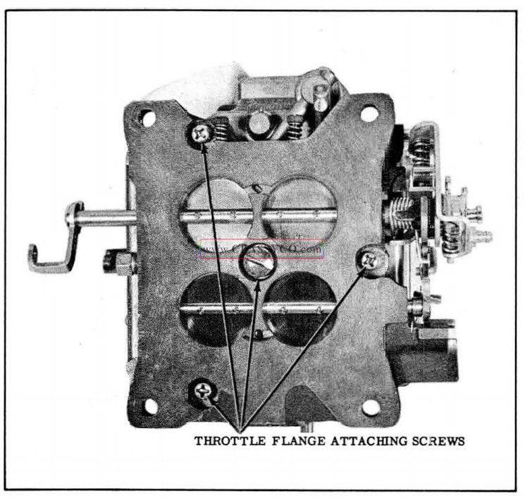
1957 Oldsmobile Throttle Flange Attaching Screws
- Remove the secondary auxiliary throttle valve assembly from the carburetor body. (See Fig. 8 -101)
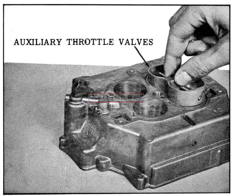
1957 Oldsmobile Auxiliary Throttle Valve Assembly
Disassembly of The Throttle Flange
NOTE: No attempt should be made to remove the throttle valve or shaft from the throttle flange as it may be impossible to reassemble the throttle valves correctly in relation to the vacuum advance and idle discharge orifices.
The idle mixture needle screws may be removed for cleaning or replacement. Also the slow and fast idle speed screws and springs can be removed and replaced if necessary.
CLEANING OF PARTS
The carburetor should not be cleaned in any solution other than a cold immersion type cleaner.
- Throughly clean carburetor castings and metal parts in carburetor cleaning solvent.
CAUTION: The choke coil, housing, and pump plunger should not be immersed in solvent. Clean pump in clean gasoline only.
- Blow all passages in casting dry with compressed air. DO NOT PASS DRILLS THROUGH JETS OR PASSAGES.
- Clean filter screens of dirt or lint.
INSPECTION OF PARTS
- Check floats for dents or excessive wear at hinge pin holes.
- Shake floats to check for leaks.
- Examine float needle and seat. If grooved, replace with a factory matched float needle, seat, and gasket assembly.
- Inspect the idle mixture adjusting needles for burrs or ridges.
- Inspect the upper and lower surfaces of the carburetor body to see that the small sealing beads are not damaged. Damaged beading may result in air or fuel leaks at that point.
- Inspect holes in pump rocker arm, fast idle cam, and throttle shaft lever. If holes are worn excessively or out of round to the extent of improper operation of the carburetor, the worn parts should be replaced.
- Inspect the steps on the fast idle cam for excessive wear. If excessive wear is noted, it should be replaced to assure proper engine operation during the warm up and choking periods.
- Inspect the pump plunger leather for cracks or creases. If the pump plunger leather is damaged, replace the pump plunger as a complete assembly.
- Inspect the throttle flange assembly.
- Inspect filter screens. If screens are distorted or plugged, they should be replaced.
As mentioned during the disassembly of the carburetor, there is a very close tolerance fit of the throttle valves in the throttle flange. Also the idle discharge orifices are drilled in relation to a properly fitting valve. Therefore, if the throttle valves, levers or shafts are worn excessively or damaged, a complete throttle flange assembly is required.
CARBURETOR ASSEMBLY
Assembly of The Throttle Flange
- Install the idle mixture needles and springs finger tight. Back out the needles 1-1/2 turns as a preliminary idle adjustment.
- If removed, install the slow and fast idle screws in the throttle levers.
Assembly of The Carburetor Body
- With the carburetor body in the inverted position, install the auxiliary throttle valve assembly so that the calibrated spring operating pin is down.
- Position the throttle flange gasket on the carburetor body so that all holes are properly aligned.
- Place the throttle flange on the carburetor body and install the four attaching screws. Tighten the 3/8″-24 center screw 9 to 10 ft. lbs. and the 12-28 outer screws 3 to 4 ft. lbs.
- Place the carburetor body upright on the holding stand.
- Install the power valve and gasket, and the two primary main metering jets.
- Install the two secondary main metering jets.
- Install the secondary venturi cluster and gasket and retain with three attaching screws and washers.
NOTE: The secondary cluster does not have idle tubes or pump discharge nozzles.
- Install the pump outlet steel ball, spring, and ”T” shaped guide.
- Install the pump inlet aluminum ball and the pump return spring in the pump plunger well. Be sure the spring is seated over the ball.
Assembly of the Air Horn
- Install the power piston in the air horn and stake the casting very lightly to hold the piston in place.
- Install the pump plunger rubber seal in the air horn by inserting the small end through from the bottom. The lips of the seal must be sealed on both sides of the cover.
- Insert the pump plunger shaft through the rubber seal and install in the pump lever with the end of the shaft pointing outward. Install retaining clip.
- Position the gasket on the air horn.
- Install both small filter screens in the air horn if they were removed for cleaning or replacement.
- Install both float need le seats and gaskets, using Tool BT-52.
NOTE: Needle seats must be installed on the same sides from which they were removed.
- Inst all both float and need le assemblies on the air horn, retaining in place with the hinge pin.
FLOAT LEVEL ADJUSTMENT
To insure proper fuel level and sufficient entry of fuel into the carburetor bowl, two adjustments of the floats are required. They are: Float Level Adjustment and Float Drop Adjustment. Since float level adjustment affects the float drop setting, the float level is always adjusted first.
The float level adjustment is made with the air horn gasket in pl ace on the air horn.
- Place Gauge BT- 89 in position on the floats. Be sure the gauge is in line with the center of the floats. (See Fig. 8-102)

1957 Oldsmobile Float Level Adjustment
- Bend the float arm a t the center to raise or lower the floats. The adjustment is correct when the bottom of the float just touches the bottom of the float gauge BT -89. (Height is 1-5/8″ ± 1/16 ” from the face of the gasket.
- With Gauge BT -89 still in place, visually check the floats to see if they are centered between the legs of the gauge. If required, bend the float arms until the floats are centered.
FLOAT DROP ADJUSTMENT
The float drop is measured between the air horn gasket and the bottom (lowest part) of the float. The adjustment is made by bending the small brass tang toward the need le seat to lessen the drop and away from the need le seat to increase the drop. The measurement and adjustment are as follows:
- Holding a six inch scale against the air horn gasket, measure the float drop as shown in Fig. 8 -103. The distance should be 2-1/ 4″ +- 1/16″.
- If adjustment is required, bend the small brass tang either away from. or toward the float needle seat to obtain the 2-1/4″ 1/16″ drop.
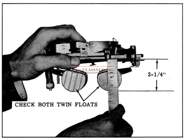
1957 Oldsmobile Float Drop Adjustment
COMPLETION OF CARBURETOR ASSEMBLY
- Carefully guide the air horn assembly on the carburetor body so that the pump plunger, power valve stem, and floats will not be damaged.
- Align the holes in the air horn, gasket, and body and just start the 13 air horn attaching screws.
- Tighten evenly and securely the inner attaching screws (including the screw through the inner wall), then tighten the remaining outside attaching screws in the same manner.
- Install the choke shaft in the air horn.
- Slide the choke valve through the shaft so that the letters “RP” on the valve are facing up when the valve is closed. (See Fig. 8 -104)
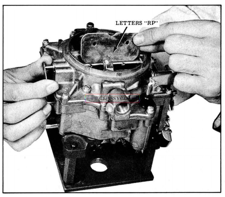
1957 Oldsmobile Installing Choke Valve
- just start two new small choke valve-to-shaft attaching screws. DO NOT tighten.
- Install the choke rod, counterweight, and fast idle cam, then install the fast idle cam attaching screw. (See Fig. 8-105)
1957 Oldsmobile Fast Idle Cam Assembly
- Position the choke trip lever over the end of the choke shaft. Be sure the small tab of the trip lever is above the choke counterweight tang. Inst all and tighten the attaching screw. (See Fig. 8-106)
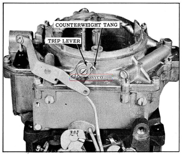
1957 Oldsmobile Installing Choke Trip Lever
- To provide the correct fit of the choke valve in the air horn, push slightly on the end of the choke shaft to obtain a minimum clearance of.020″ between the trip lever and choke counterweight as shown in Fig. 8 -107.
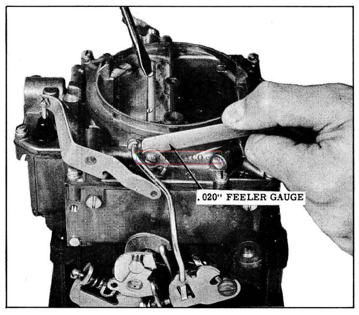
1957 Oldsmobile Adjusting Fit of Choke Valve
- While holding the choke shaft in this position, tighten the choke valve retaining screws. Check for free operation of the choke valve in the air horn.
- Insert the grooved end of the pump rod through the hole in the throttle lever, then install the small horseshoe type retainer.
- Inst all the upper end of the pump rod (with spring retaining clip) on the p ump lever.
- Install the choke housing gasket and then the intermediate choke shaft in the choke housing. (See Fig. 8-108)
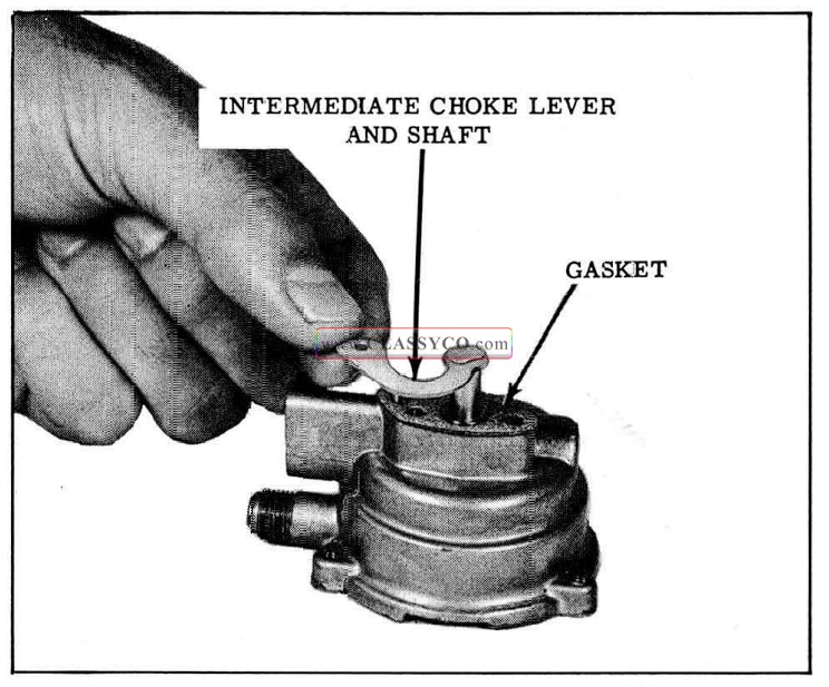
1957 Oldsmobile lntermediate Choke Lever
- Install the choke housing on the carburetor body and retain with two attaching screws. Be sure the intermediate choke shaft lever is extending downward between the two attaching screw bosses.
- Install the choke lever, link, and piston assembly and attach the lever to the intermediate choke shaft
- Rotate the intermediate choke shaft to check for free movement of the shaft and piston.
- Install the intermediate choke rod, with ends pointing in, and retain with spring clips.
- Adjust intermediate choke rod as outlined under ADJUSTMENTS (ON OR OFF THE CAR).
- Place the baffle plate in position in the choke housing.
- Install the choke cover gasket, cover and coil assembly, and three screws and retainers.
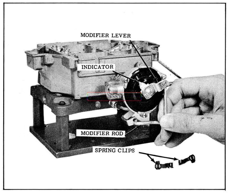
- Install the choke modifier pointer and lever on the choke cover, then loosely install the attaching screw.
- Attach the choke modifier rod to the modifier lever and to the throttle shaft lever, using spring clips. The modifier lever should point toward the right when the rod is properly installed. (See Fig. 8-109)
1957 Oldsmobile Checking Choke Piston Position
- Adjust choke modifier and choke rod as out lined under ADJUSTMENTS (ON OR OFF THE CAR).
- Install the fuel inlet screen, fitting gasket and fitting in the air horn, if they were removed.
- Install the throttle return check to carburetor body. Attach vacuum line connecting throttle return check to throttle flange.
- Adjust unloader, secondary lockout and secondary throttle contour clearance as outlined under ADJUSTMENTS (ON OR OFF THE CAR).
ADJUSTMENTS (ON OR OFF CAR)
INTERMEDIATE CHOKE ROD ADJUSTMENT
The choke vacuum piston must be properly positioned with respect to the vacuum slots in the choke housing bore to provide proper choke pull off action.
- With choke cover and baffle removed, hold the choke valve closed, push lightly on the end of the choke piston to remove all lash in the linkage, and then check to see if the choke piston is flush with the choke piston bore. (See Fig. 8-110)
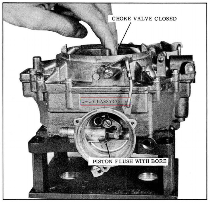
1957 Oldsmobile Installing Choke Modifier Rod
- Bend the intermediate choke rod, if necessary, to correctly position the choke piston.
- Install choke baffle and cover.
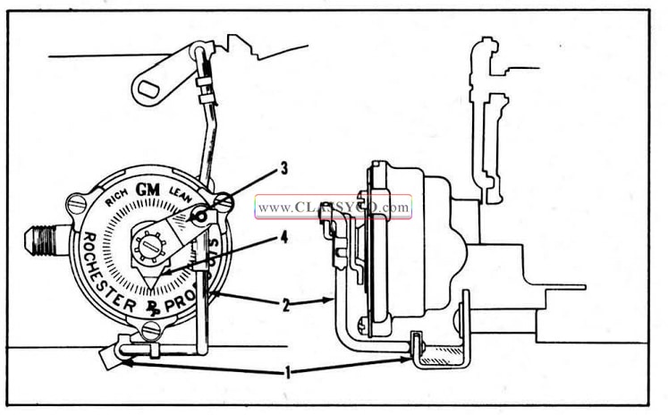
CHOKE MODIFIER ADJUSTMENT
- Back off the fast idle screw and slow idle screw so that the throttle valves are in their fully closed position.
- With the modifier lever retaining screw loose, rotate the meta indicator on the choke cover counterclockwise from its free position until the thermostatic spring begins to close the choke valve, then continue until the indicator lines up with the index mar k on the cover. (See Fig. 8-111)
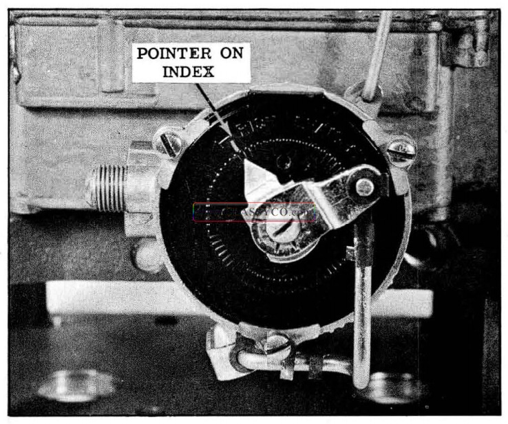
1957 Oldsmobile Choke Modifier Adjustment
- While holding the indicator in this position, tighten the retaining screw. Be sure the indica tor remains on the index mark after the screw is tightened.
PUMP ROD ADJUSTMENT
To insure correct fuel delivery from the pump, it is important that the pump rod be accurately set. The adjustment procedure is as follows:
- While holding the throttle valves closed, measure the distance from the top of the air horn casting to the bottom edge of the pump plunger shaft. It should be 1-3/64″ +- 1/64″. (See Fig. 8-112)
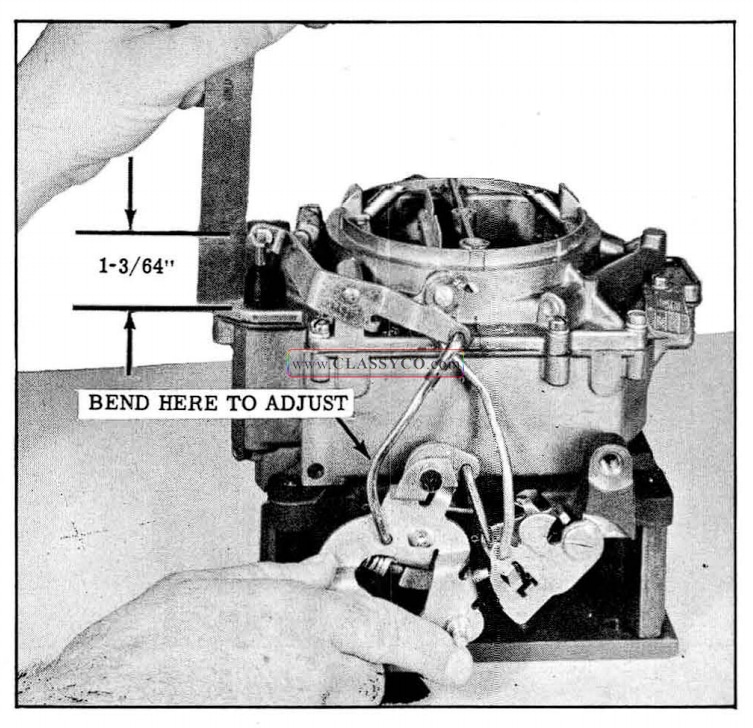
1957 Oldsmobile Pump Rod Adjustment
- Bend the pump rod, if necessary to obtain the correct dimensions, using Tool BT -18.
- Operate the pump rod several times to be sure the movement is free.
CHOKE ROD ADJUSTMENT
In addition to the intermediate choke rod adjustment and choke modifier adjustment, it is necessary to adjust the choke rod to the fast idle cam. This insures proper positioning of the fast idle cam when the choke valve is in operation.
- Turn in the fast idle screw until it just contacts the inter mediate step (middle step) of the fast idle cam.
- With the shoulder of the highest step of the fast idle cam held against the fast idle screw, check the clearance between the top edge of the choke valve and the dividing wall of the air horn. The correct clearance is.053″.010 ” and can be checked with the small end of the gauge BT -68. (See Fig. 8 -113)
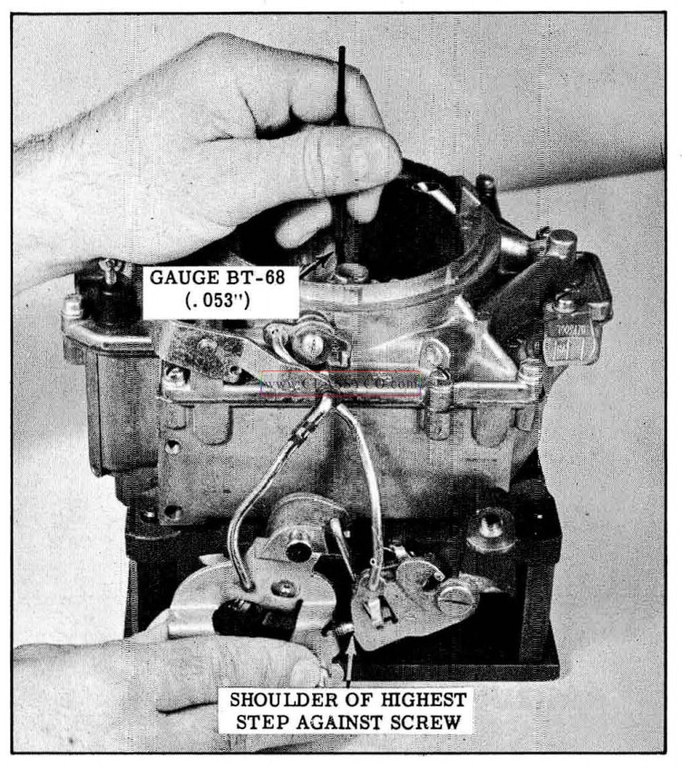
1957 Oldsmobile Choke Rod Adjustment
- If necessary, bend the choke rod to obtain the correct dimension.
UNLOADER ADJUSTMENT
If the engine “loads up” or becomes flooded when cold starting, it is necessary to mechanically open the choke valve a small amount to admit more air and facilitate starting. This is accomplished when the throttle lever contacts a tang on the fast idle cam at wide-open throttle. This feature is called the unloader and the adjustment procedure is as follows:
- Be sure the choke modifier adjustment is correct and the trip lever is in contact with the choke counter-weight.
- While holding the throttle lever in the wide open position (with carburetor off car), or with accelerator pedal completely depressed (with carburetor on car), check the clearance be tween the top edge of the choke valve and the dividing wall. The correct clearance is.092″ ±.015″ and can be checked with gauge BT-68. (See Fig. 8-114)
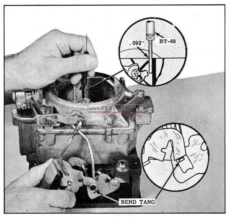
1957 Oldsmobile Unloader Adjustment
- If necessary, bend the small tang on the fast idle cam with Tool BT-91 to obtain the correct dimension.
IMPORTANT: If the unloader adjustment was made off the car, it will be necessary to re check the adjustment with the accelerator pedal completely depressed after the carburetor is installed.
SECONDARY THROTTLE LOCK-OUT ADJUSTMENT
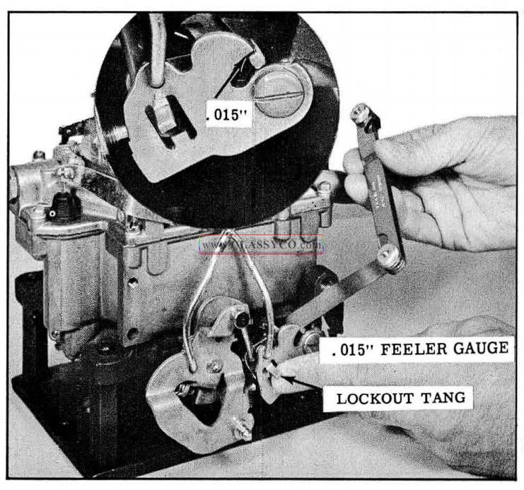
A secondary throttle lock-out is designed into the carburetor to prevent opening of the secondary throttle valves until ‘ the engine has reached normal operating temperature.
The lock-out adjustment provides sufficient clearance between the tang and the fast idle cam so that the fast idle cam will be in the locked position when the choke closes. Insufficient clearance at the lock point will allow the fast idle cam to strike the tang when the choke closes and prevent lock-out action.
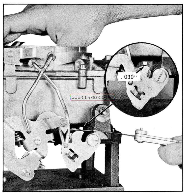
The secondary throttle contour clearance adjustment, which is performed after the lock-out adjustment, actually times the unlocking of the secondary throttle valves in relation to engine temperature. Insufficient clearance will not allow the secondary throttle valves to unlock. Excessive clearance will allow the secondary throttle valves to unlock at temperatures lower than normal.
- Hold the choke valve partially closed so that the secondary throttle lock-out tang is in line with the top of the slot in the fast idle cam.
- Measure the clearance between the lock-out tang and the top edge of the slot in the fast idle cam. The clearance should be.015″± .005″. (See Fig. 8-115)
1957 Oldsmobile Secondary Lock-Gut Adjustment
- If adjustment is necessary, bend the tang sideways using Tool BT-18 until the proper clearance is obtained.
SECONDARY THROTTLE CONTROL CLEAIRANCE ADJUSTMENT
- Hold the choke valve in the wide open position so that the secondary lock-out tang is positioned over the fast idle cam, then measure the clearance between the tang and the fast idle cam. The clearance should be.030″ ±.010″. (See Fig. 8-116)
1957 Oldsmobile Secondary Throttle Clearance
- If adjustment is necessary, allow the choke to close so that the tang is again in the slot of the fast idle cam, then use Tool BT-91 to bend the tang straight up or down as required for proper clearance.
ADJUSTMENTS (ON CAR)
There are four adjustments that must be made with the carburetor mounted on the engine. They are: Slow Idle Adjustment, Fast Idle Adjustment, Atmospheric Vent Adjustment, and Throttle Re turn Check Adjustment.
SLOW IDLE ADJUSTMENT (Air Cleaner Removed)
Engine must be at operating temperature and throttle return check Holding Fixture J -6342 in place.
On cars equipped with ai r conditioning, compressor clutch must be engaged.
H.M.T. in “D” – 425 R.P.M.
S.M.T. in “Neutral” – 450 R.P.M.
After the idle R.P.M. is stabilized, turn in or out each idle adjusting needle screw until the smoothest possible idle is obtained. This normally is accompanied by a higher manifold vacuum reading and/or an increase of idle R.P.M. Then, turn out (rich) each needle 1/4 turn, at which time both the idle vacuum and R.P.M. will drop off slightly. This adjustment will prove to be correct for all normal idle requirements.
FAST IDLE ADJUSTMENT
When the engine is cold and the choke valve is partially closed, it is necessary that the engine R.P.M. a t idle be higher than nor mal to prevent stalling. This adjustment, if correct, will assure proper engine R.P.M. during the warm-up period.
- Rotate the fast idle cam so that the fast idle screw is resting on the high step of the cam. (See Fig. 8-117)
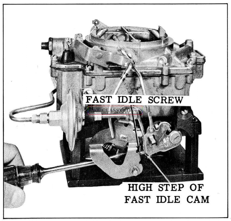
1957 Oldsmobile Fast Idle Adjustment
- With the engine running at operating temperature and transmission selector lever in neutral, adjust the fast idle screw to obtain an engine speed of 1500-1600 R.P.M.
THROTTLE RETURN CHECK ADJUSTMENT
The throttle return check is designed to open the throttle valves to increase engine speed when engine vacuum drops if the engine loads up and starts to stall. It also acts to retard throttle closing when the driver suddenly takes his foot off the accelerator pedal.
- Be sure the fast idle adjustment has been made, then shut off the engine.
- Rotate the fast idle cam so that the fast idle screw rests on top of the highest step of the fast idle cam.
- Measure the clearance between the contact screw and the contact on the throttle lever. The clearance should be .020″. (SeeFig. 8-118)
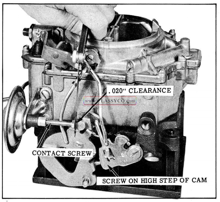
1957 Oldsmobile Throttle Return Check Adjustment
- If adjustment is necessary, adjust the contact screw using two wrenches.
NOTE: Any time the slow or fast idle is changed, it will be necessary to readjust the throttle return check.
ATMOSPHERIC IDLE VENT ADJUSTMENT (ON CAR)
The atmospheric idle vent is designed to vent any vapor formed in the float bowl during slow idle operation. It is opened by a tang on the pump lever whenever the throttle valves are in the slow idle position.
- Open the primary throttle valve until the secondary valve just begins to open. The atmospheric idle vent operating tang should just contact the idle vent valve.
- If necessary to adjust, use Tool BT-67 to bend the tang on the pump arm. (See Fig. 8-119)
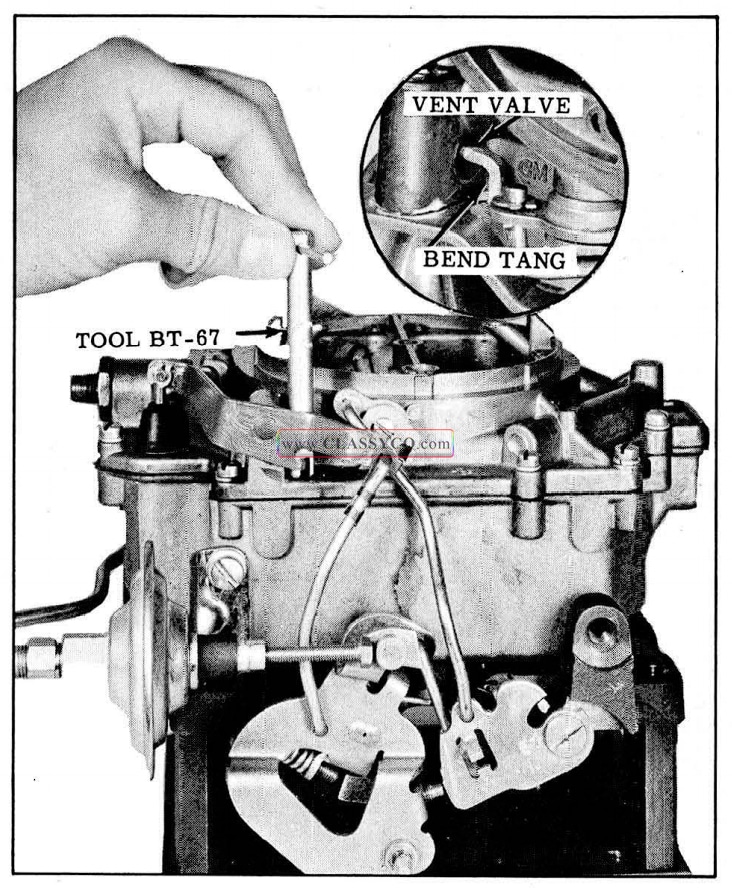
1957 Oldsmobile Idle Vent Adjustment
1957 Oldsmobile S88 Convertible Coupe (DCR)